

Inductive sensor
BI1-EG05-AN6X-V1331
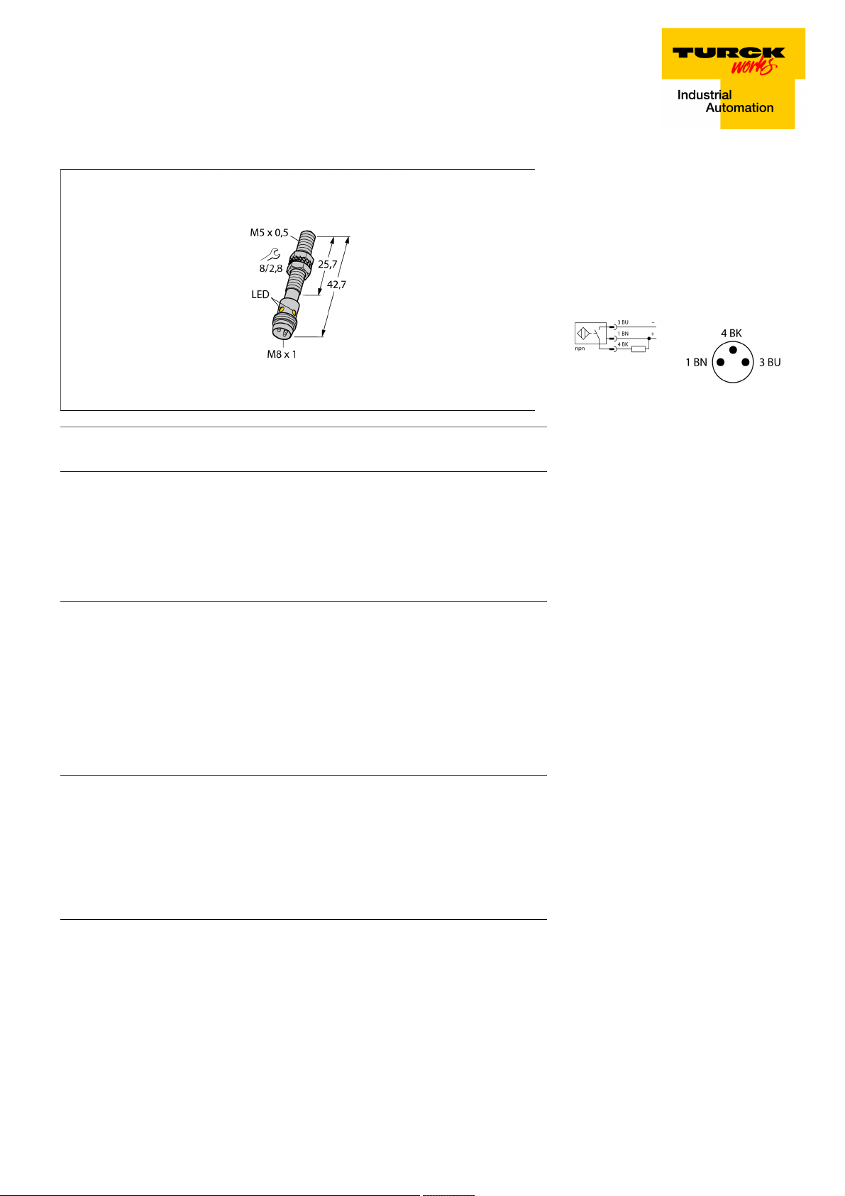
■ M5 × 0.5 threaded barrel
■ Stainless steel, 1.4427 SO
■ DC 3-wire, 10…30 VDC
■ NO contact, NPN output
■ M8 x 1 male connector
Wiring Diagram
Type designation BI1-EG05-AN6X-V1331
Ident-No. 4608740
Rated switching distance Sn 1 mm
Mounting conditions Flush
Secured operating distance
Correction factors St37 = 1; Al = 0.3; stainless steel = 0.7; Ms = 0.4
Repeat accuracy
Temperature drift
Hysteresis 3…15 %
Ambient temperature -25…+70 °C
Operating voltage 10…30 VDC
Residual ripple
DC rated operational current
No-load current I
Residual current
Isolation test voltage
Short-circuit protection yes/ Cyclic
Voltage drop at I
Wire breakage/Reverse polarity protection yes/ Complete
Output function 3-wire, NO contact, NPN
Switching frequency 3 kHz
Design Threaded barrel,M5 × 0.5
Dimensions 42.7 mm
Housing material Stainless steel, 1.4427 SO
Max. tightening torque housing nut 5 Nm
Electrical connection Connector, M8 × 1
Vibration resistance 55 Hz (1 mm)
Shock resistance 30 g (11 ms)
Protection class IP67
MTTF 2283 years acc. to SN 29500 (Ed. 99) 40 °C
0
e
ð (0,81 x Sn) mm
ð 2 % of full scale
ð ± 10 %
ð 10 % U
ss
ð 100 mA
ð 15 mA
ð 0.1 mA
ð 0.5 kV
ð 1.8 V
Functional principle
Inductive sensors detect metal objects contactless and wear-free. For this, they use a
high-frequency electromagnetic AC field that
interacts with the target. Inductive sensors
generate this field via an RLC circuit with a
ferrite coil.
Switching state LED,Yellow
Edition • 2018-04-24T17:48:30+02:00
1 / 3 TURCK Inc.
Inductive sensor
BI1-EG05-AN6X-V1331
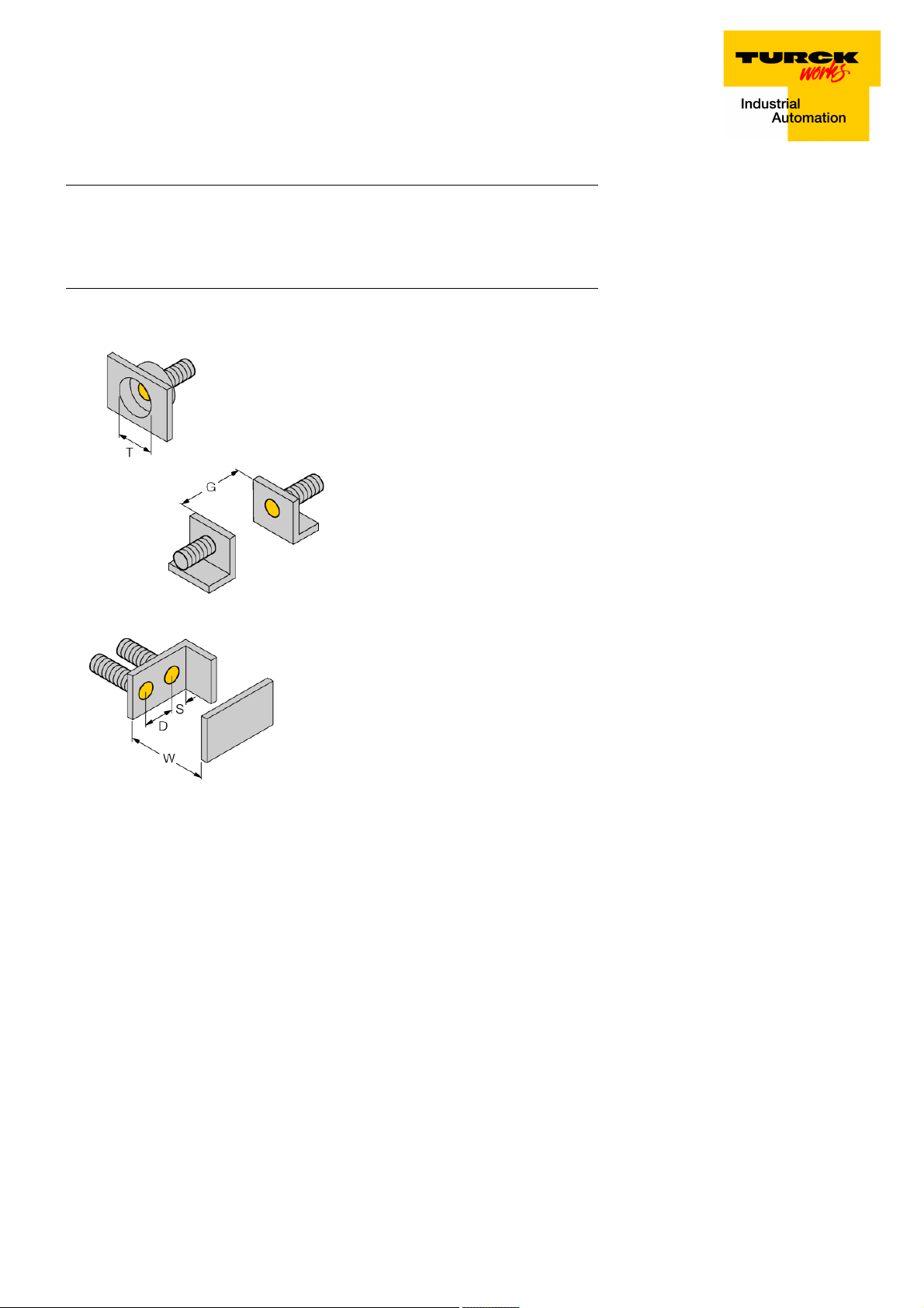
Distance D 2 x B
Distance W 3 x Sn
Distance T 3 x B
Distance S 1.5 x B
Distance G 6 x Sn
Diameter active area B Ø 5 mm
Edition • 2018-04-24T17:48:30+02:00
2 / 3 TURCK Inc.

Inductive sensor
BI1-EG05-AN6X-V1331
Wiring accessories
Type code Ident-No. Description
PKGV3M-2/TEL 6625385 Connection cable, female M8, straight, 3-pin, stainless steel
coupling nut, cable length: 2 m, sheath material: PVC, black;
cULus approval; other cable lengths and qualities available,
see www.turck.com
Edition • 2018-04-24T17:48:30+02:00
3 / 3 TURCK Inc.
 Loading...