

Page 1
BI1.5-EG08-Y1-V1131
Inductive Sensor
Technical data
Type
Ident. no. 1003530
Rated switching distance 1.5mm
Mounting conditions Flush
Secured operating distance ≤(0.81×Sn)mm
Correction factors St37 = 1; Al = 0.3; stainless steel = 0.7; Ms
Repeat accuracy ≤2% of full scale
Temperature drift ≤ ± 10 %
Hysteresis 1…10%
Ambient temperature -25…+70°C
Output function 2-wire, NAMUR
Switching frequency 5kHz
Voltage Nom.8.2VDC
Non-actuated current consumption ≥2.1mA
Actuated current consumption ≤1.2mA
Approval acc. to KEMA 02 ATEX 1090X
Internal capacitance (Ci)/inductance (Li) 150 nF/150 µH
Device marking
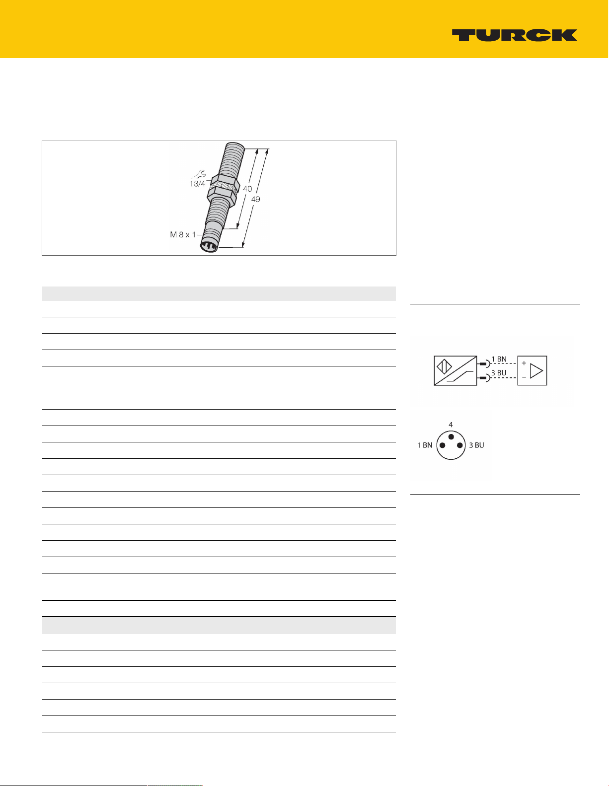
Design
Dimensions 49mm
Housing material Stainless steel, 1.4427 SO
Active area material Plastic, PA12-GF30
Max. tightening torque of housing nut 5Nm
Electrical connection Connector,M8 × 1
Vibration resistance 55Hz (1 mm)
BI1.5-EG08-Y1-V1131
= 0.4
É II 1 G Ex ia IIC T6 Ga/II 1 D Ex ia IIIC
T95 °C Da
(max. Ui = 20 V, Ii = 60 mA, Pi = 130 mW)
Threaded barrel,M8 × 1
Features
Threaded barrel, M8 x 1
■
Stainless steel, 1.4427 SO
■
DC 2-wire, nom. 8.2 VDC
■
Output acc. to DIN EN 60947-5-6 (NAMUR)
■
M8 x 1 male connector
■
ATEX category II 1 G, Ex zone 0
■
ATEX category II 1 D, Ex zone 20
■
SIL2 (Low Demand Mode) acc. to IEC 61508,
■
PL c acc. to ISO 13849-1 at HFT0
SIL3 (All Demand Mode) acc. to IEC 61508,
■
PL e acc. to ISO 13849-1 with redundant
configuration HFT1
Wiring diagram
Functional principle
Inductive sensors detect metal objects
contactless and wear-free. For this, they use a
high-frequency electromagnetic AC field that
interacts with the target. Inductive sensors
generate this field via an RLC circuit with a
ferrite coil.
BI1.5-EG08-Y1-V1131 | 12/03/2020 04-26 | technical changes reserved
TURCK Inc. | 3000 Campus Drive Minneapolis, MN 55441-2656 | Phone: 763-553-7300 | Application Support: 1-800-544-7769 | Fax 763-553-0708 | www.turck.com
1|4
Page 2
Technical data
Shock resistance 30g (11 ms)
Protection class IP67
MTTF 6198years acc. to SN 29500 (Ed. 99) 40
°C
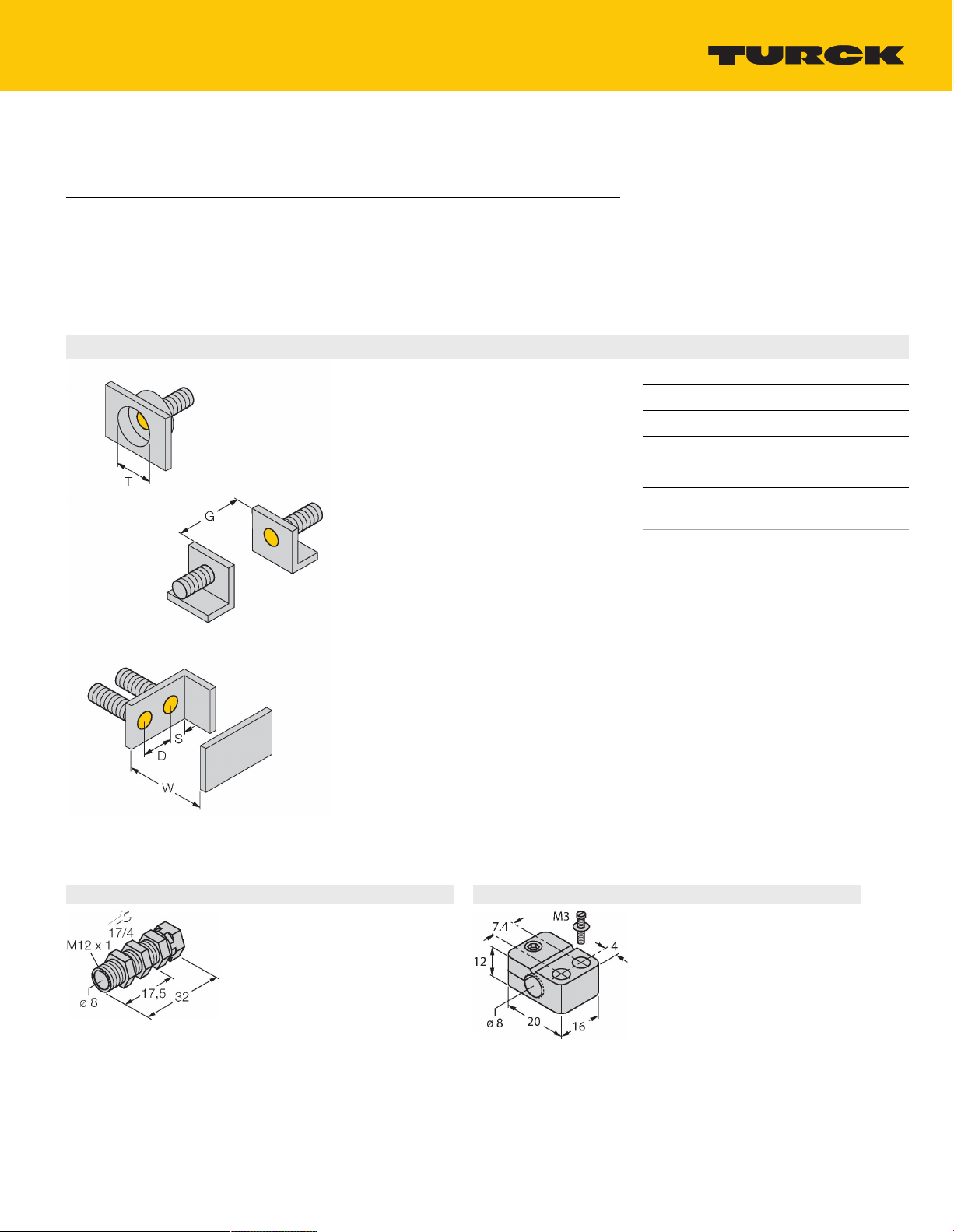
Mounting instructions
Mounting instructions/Description
Distance D 2 x B
Distance W 3 x Sn
Distance T 3 x B
Distance S 1.5 x B
Distance G 6 x Sn
Diameter active
Ø8mm
area B
Accessories
QM-08 6945100
Quick-mount bracket with deadstop, chrome-plated brass, male
thread M12 x 1. Note: The switching
distance of proximity switches may
be reduced through the use of quickmount brackets.
TURCK Inc. | 3000 Campus Drive Minneapolis, MN 55441-2656 | Phone: 763-553-7300 | Application Support: 1-800-544-7769 | Fax 763-553-0708 | www.turck.com
BST-08B 6947210
Mounting clamp for threaded barrel
sensors, with dead-stop; material:
PA6
BI1.5-EG08-Y1-V1131 | 12/03/2020 04-26 | technical changes reserved
2|4
Page 3

MW-08 6945008
Mounting bracket for threaded barrel
sensors; material: Stainless steel A2
1.4301 (AISI 304)
MBS80 69479
Mounting clamp for smooth barrel
sensors; mounting block material:
Anodized aluminum
BSS-08 6901322
Mounting clamp for smooth and
threaded barrel sensors; material:
Polypropylene
TURCK Inc. | 3000 Campus Drive Minneapolis, MN 55441-2656 | Phone: 763-553-7300 | Application Support: 1-800-544-7769 | Fax 763-553-0708 | www.turck.com
BI1.5-EG08-Y1-V1131 | 12/03/2020 04-26 | technical changes reserved
3|4
Page 4

Operating Instructions
Intended use
This device fulfills the directive 2014/34/EC and is suited for use in explosion hazardous areas according to EN
60079-0:2012 + A11 and EN 60079-11:2012.Further it is suited for use in safety-related systems, including SIL2 as per IEC
61508.In order to ensure correct operation to the intended purpose it is required to observe the national regulations and
directives.
For use in explosion hazardous areas conform to classification
II 1 G and II 1 D (Group II, Category 1 G, electrical equipment for gaseous atmospheres and category 1 D, electrical equipment for
dust atmospheres).
Marking (see device or technical data sheet)
É II 1 G and Ex ia IIC T6 Ga and É II 1 D Ex ia IIIC T95 °C Da acc. to EN 60079-0, -11
Local admissible ambient temperature
-25…+70 °C
Installation/Commissioning
These devices may only be installed, connected and operated by trained and qualified staff. Qualified staff must have
knowledge of protection classes, directives and regulations concerning electrical equipment designed for use in
explosion hazardous areas.Please verify that the classification and the marking on the device comply with the actual
application conditions.
This device is only suited for connection to approved Exi circuits according to EN 60079-0 and EN 60079-11. Please
observe the maximum admissible electrical values.After connection to other circuits the sensor may no longer be
used in Exi installations. When interconnected to (associated) electrical equipment, it is required to perform the "Proof
of intrinsic safety" (EN60079-14).Attention! When used in safety systems, all content of the security manual must be
observed.
Installation and mounting instructions
Avoid static charging of cables and plastic devices. Please only clean the device with a damp cloth. Do not install the
device in a dust flow and avoid build-up of dust deposits on the device.If the devices and the cable could be subject to
mechanical damage, they must be protected accordingly. They must also be shielded against strong electro-magnetic
fields.The pin configuration and the electrical specifications can be taken from the device marking or the technical
data sheet.In order to avoid contamination of the device, please remove possible blanking plugs of the cable glands or
connectors only shortly before inserting the cable or opening the cable socket.
Service/Maintenance
Repairs are not possible. The approval expires if the device is repaired or modified by a person other than the
manufacturer. The most important data from the approval are listed.
BI1.5-EG08-Y1-V1131 | 12/03/2020 04-26 | technical changes reserved
TURCK Inc. | 3000 Campus Drive Minneapolis, MN 55441-2656 | Phone: 763-553-7300 | Application Support: 1-800-544-7769 | Fax 763-553-0708 | www.turck.com
4|4
 Loading...