

Turck BI1.5-EG08-Y1-H1341 Datasheet
BI1.5-EG08-Y1-H1341
Inductive Sensor
Features
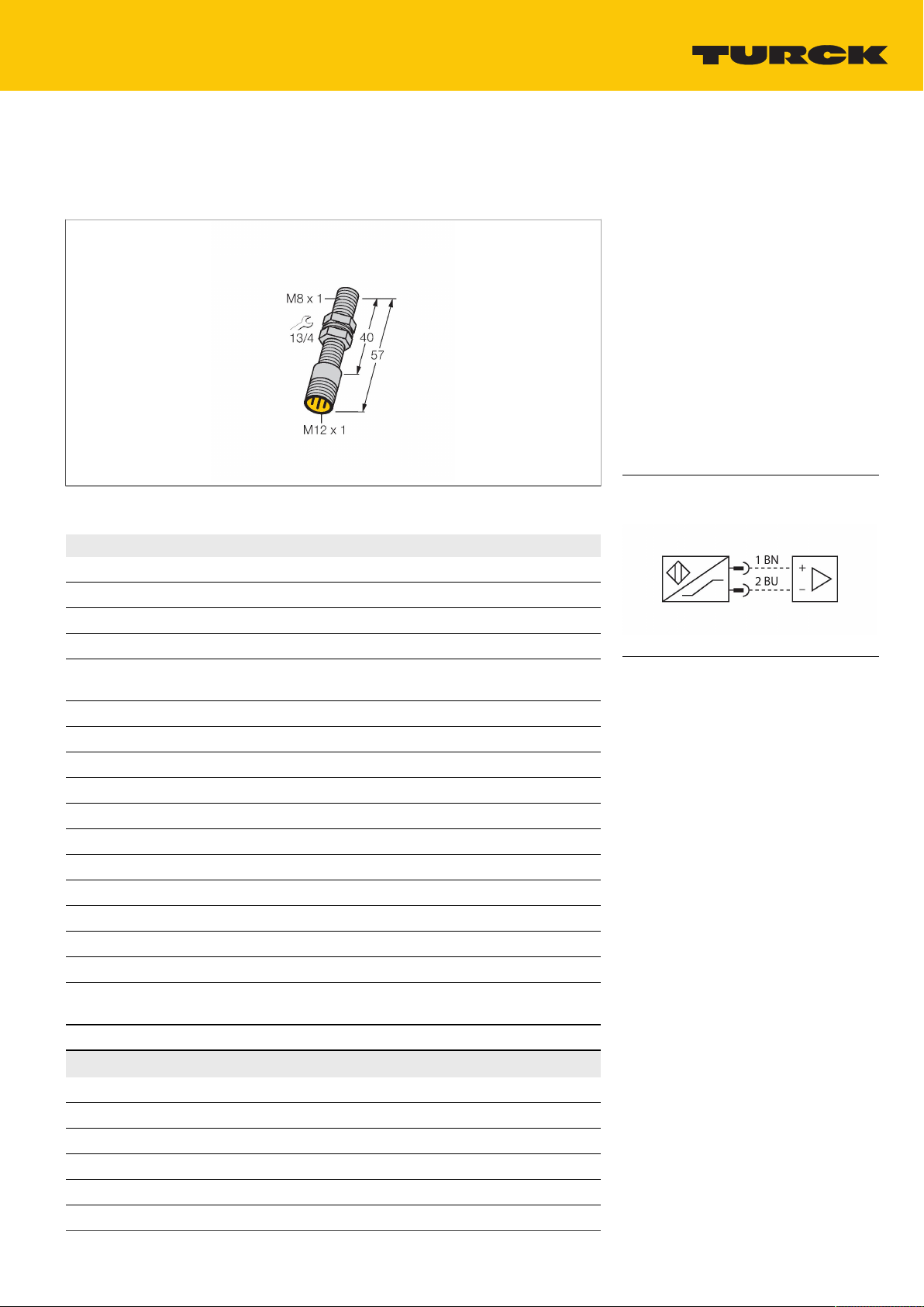
Threaded barrel, M8 x 1
■
Stainless steel, 1.4427 SO
■
DC 2-wire, nom. 8.2 VDC
■
Output acc. to DIN EN 60947-5-6 (NAMUR)
■
M12 x 1 male connector
■
ATEX category II 1 G, Ex zone 0
■
ATEX category II 1 D, Ex zone 20
■
SIL2 (Low Demand Mode) acc. to IEC
■
61508, PL c acc. to ISO 13849-1 at HFT0
SIL3 (All Demand Mode) acc. to IEC 61508,
■
PL e acc. to ISO 13849-1 with redundant
configuration HFT1
Technical data
Type
ID no. 1003502
Rated switching distance 1.5mm
Mounting conditions Flush
Secured operating distance ≤(0.81×Sn)mm
Correction factors St37 = 1; Al = 0.3; stainless steel = 0.7;
Repeat accuracy ≤2% of full scale
Temperature drift ≤ ± 10 %
Hysteresis 1…10%
Ambient temperature -25…+70°C
Output function 2-wire, NAMUR
Switching frequency 5kHz
Voltage Nom.8.2VDC
Non-actuated current consumption ≥2.1mA
Actuated current consumption ≤1.2mA
Approval acc. to KEMA 02 ATEX 1090X
Internal capacitance (Ci)/inductance (Li) 150 nF/150 µH
Device marking
Design
Dimensions 57mm
Housing material Stainless steel, 1.4427 SO
Active area material Plastic, PA12-GF30
Max. tightening torque of housing nut 5Nm
Electrical connection Connectors,M12 × 1
Vibration resistance 55Hz (1 mm)
BI1.5-EG08-Y1-H1341
Ms = 0.4
É II 1 G Ex ia IIC T6 Ga/II 1 D Ex ia IIIC
T95 °C Da
(max. Ui = 20 V, Ii = 60 mA, Pi = 130 mW)
Threaded barrel,M8 × 1
Wiring diagram
Functional principle
Inductive sensors detect metal objects
contactless and wear-free. For this, they use a
high-frequency electromagnetic AC field that
interacts with the target. Inductive sensors
generate this field via an RLC circuit with a
ferrite coil.
BI1.5-EG08-Y1-H1341 | 22-04-2021 15-49 | Technical modifications reserved
Hans Turck GmbH & Co. KG | 45466 Mülheim an der Ruhr, Germany | T +49 208 4952-0 | F +49 208 4952-264 | more@turck.com | www.turck.com 1|4
Technical data
Shock resistance 30g (11 ms)
Protection class IP67
MTTF 6198years acc. to SN 29500 (Ed. 99) 40
°C
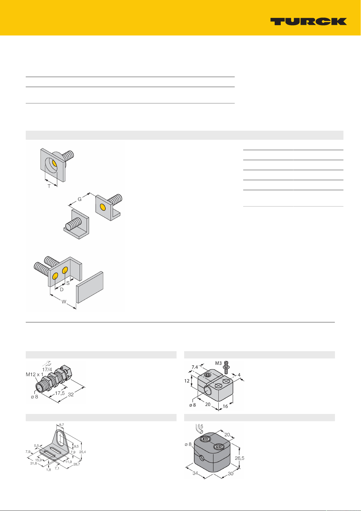
Mounting instructions
Mounting instructions/Description
Distance D 2 x B
Distance W 3 x Sn
Distance T 3 x B
Distance S 1.5 x B
Distance G 6 x Sn
Diameter active
Ø8mm
area B
Accessories
QM-08 6945100
Quick-mount bracket with deadstop, chrome-plated brass, male
thread M12 x 1. Note: The switching
distance of proximity switches may
be reduced through the use of quickmount brackets.
MW-08 6945008
Mounting bracket for threaded barrel
sensors; material: Stainless steel A2
1.4301 (AISI 304)
Hans Turck GmbH & Co. KG | 45466 Mülheim an der Ruhr, Germany | T +49 208 4952-0 | F +49 208 4952-264 | more@turck.com | www.turck.com 2|4
BST-08B 6947210
Mounting clamp for threaded barrel
sensors, with dead-stop; material:
PA6
BSS-08 6901322
Mounting clamp for smooth and
threaded barrel sensors; material:
Polypropylene
BI1.5-EG08-Y1-H1341 | 22-04-2021 15-49 | Technical modifications reserved
 Loading...