

turck BCT5-S18-UP6X2T-H1151, BCT10-S30-UN6X2T-H1151, BCT5-S18-UP6X2-H1151, BCT10-S30-UP6X2-H1151, BCT10-S30-UN6X2-H1151 Operating Instructions Manual
...Page 1

Your Global Automation Partner
Operating Instructions
BCT-…
Teachable Capacitive
Sensors
Page 2

2
Hans Turck GmbH & Co. KG | T +49 208 4952-0 | F +49 208 4952-264 | more@turck.com | www.turck.com
Page 3

1 About These Instructions 5
1.1 Target groups 5
1.2 Explanation of symbols 5
1.3 Other documents 6
1.4 Feedback about these instructions 6
2 Notes on the Product 7
2.1 Product identication 7
2.2 Scope of delivery 7
2.3 Legal requirements 7
2.4 Manufacturer and service 8
3 For your safety 8
3.1 Intended use 8
3.2 Obvious misuse 8
3.3 General safety notes 8
4 Product description 9
4.1 Device overview 9
4.1.1 Indication elements 9
4.1.2 Operating elements 9
4.2 Properties and features 10
4.3 Operating principle 10
4.4 Functions and operating modes 10
4.4.1 Setting options 10
4.4.2 “Medium present” mode (Full teach) 10
4.4.3 “Medium not present” mode (Empty teach) 10
4.4.4 “Switch point between medium present and medium not present” mode
(Complete teach) 11
4.4.5 Internal voltage and temperature monitoring 11
4.5 Technical accessories 11
5 Mounting 13
6 Connection 14
6.1 Wiring diagrams 14
7 Commissioning 14
8 Operation 15
8.1 Operation in IO-Link mode – LED indication 15
9 Setting 16
9.1 Setting via the teach adapter 16
9.2 Setting by manual bridging (shorting) 17
9.3 Setting via pushbuttons 18
9.4 Setting via IO-Link 19
9.4.1 IO-Link parameters 20
9.5 Example of use: Adjust sensor for poorly detectable media 20
3
2016/09
BCT-... Capacitive Sensors
Page 4

10 Troubleshooting 21
11 Maintenance 21
12 Repair 21
12.1 Returning devices 21
13 Decommissioning 21
14 Disposal 21
15 Technical Data 22
4
Hans Turck GmbH & Co. KG | T +49 208 4952-0 | F +49 208 4952-264 | more@turck.com | www.turck.com
Page 5

5
2016/09
BCT-... Capacitive Sensors
1 About These Instructions
These instructions describe the setup, the functions and use of the device and help you to operate the product for its intended use. Read these instructions carefully prior to using the product.
Keep these instructions safe during the service life of the device. If the product is passed on,
pass on these instructions as well.
1.1 Target groups
This document is written for specially trained personnel and must be read carefully by anyone
who is charged with the mounting, commissioning, operation, maintenance, disassembly or
disposal of the device.
1.2 Explanation of symbols
The following symbols are used in these instructions:
DANGER
DANGER indicates a direct hazardous situation with the risk of death or serious injury if
it is not prevented.
WARNING
WARNING indicates a possible hazardous situation with the risk of death or serious
injury if it is not prevented.
NOTICE
NOTICE indicates a situation that may cause possible damage to property if it is not
prevented.
NOTE
NOTE indicates tips, recommendations and important information. The notes contain
information, particular operating steps that facilitate work and possibly help to avoid
additional work resulting from incorrect procedures.
➤
MANDATORY ACTION
This symbol denotes actions that the user must carry out.
➥
RESULT OF ACTION
This symbol denotes the relevant results of actions and procedures.
Page 6

6
Hans Turck GmbH & Co. KG | T +49 208 4952-0 | F +49 208 4952-264 | more@turck.com | www.turck.com
About These Instructions
1.3 Other documents
Besides this document the following material can be found on the Internet at www.turck.com:
■
Data sheet of the particular device
■
IODD file
■
IO-Link Parameters Manual
All Turck software components and the IODD can be downloaded via the Turck
Software Manager. The Turck Software Manager can be downloaded free of charge at
www.turck.com.
1.4 Feedback about these instructions
We make every effort to ensure that these instructions are as informative and as clear as possible. If you have any suggestions for improving the design or if some information is missing in
the document, please send your suggestions to techdoc@turck.com.
Page 7
7
2016/09
BCT-... Capacitive Sensors
2 Notes on the Product
2.1 Product identication
Teachable capacitive sensors
BCT5-S18-UP6X2T-H1151 BCT10-S30-UP6X2T-H1151
BCT5-S18-UN6X2T-H1151 BCT10-S30-UN6X2T-H1151
BCT5-S18-UP6X2-H1151 BCT10-S30-UP6X2-H1151
BCT5-S18-UN6X2-H1151 BCT10-S30-UN6X2-H1151
2.2 Scope of delivery
The scope of delivery consists of the device and two nuts for mounting.
2.3 Legal requirements
The product is subject to the following EC directive:
■
2014/30/EC (EMC Directive)
The EC declaration of conformity is available for download from the Turck product database.
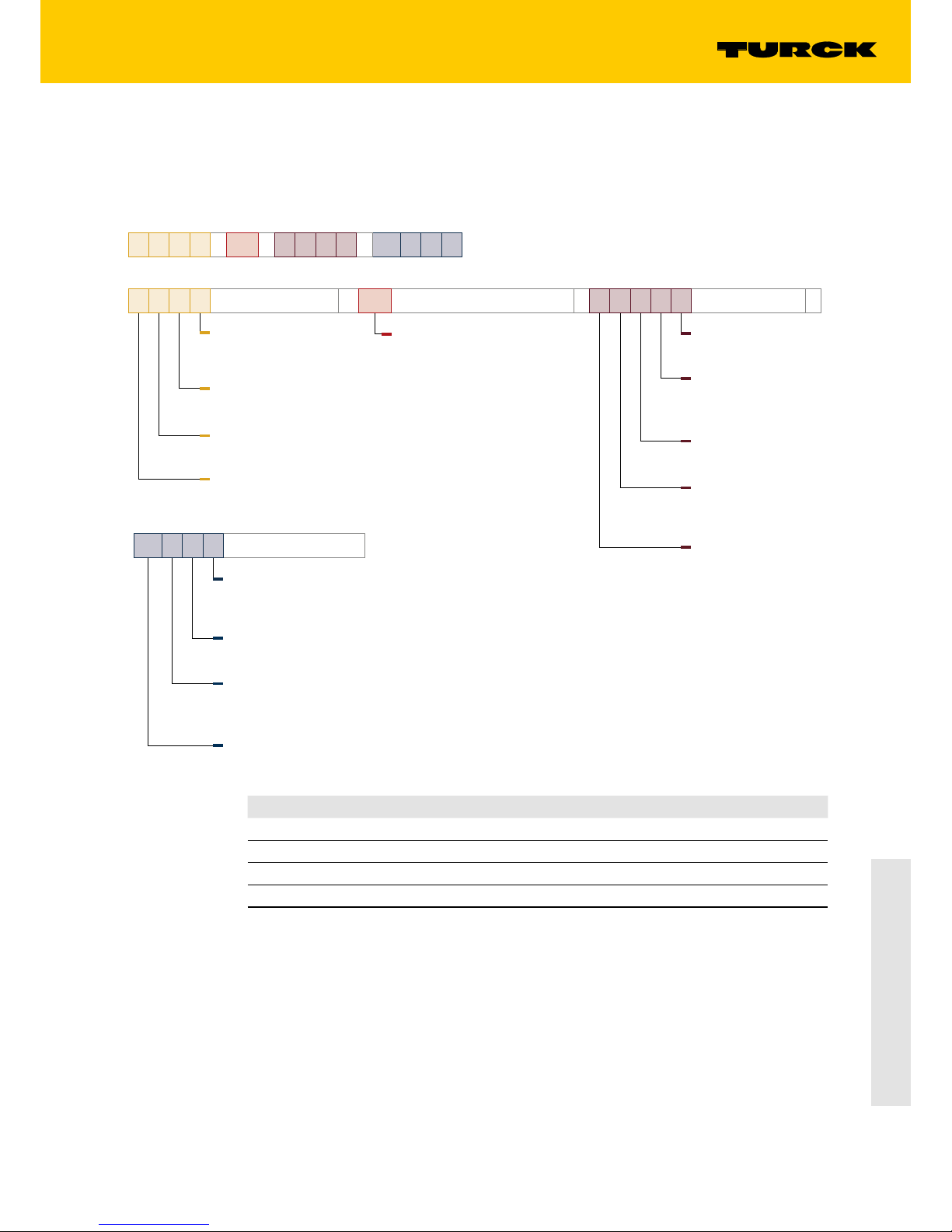
B C T 10 – S30 – U P 6 X2 – H1 1 5 1
B C T 10
Functional principle
–
Rated operating distance
… switching distance
Sn in [mm]
Special functions
T teachable
Functional principle
C capacitive
Installation
B flush
S30
Design
–
Housing
S18 cylinder, plastic,
continuous thread Ø 18 mm
S30 cylinder, plastic,
continuous thread Ø 30 mm
U P 6 X2 T
Electrical version
–
Teach button
T teach button
Indication
X LED
2 number of LEDs
Voltage range
6 10…30 VDC
Output type
N NPN output
P PNP output
Output function
U NO/NC programmable
H1 1 5 1
Electrical connection
Assignment
1 standard assignment
or customized
Number of contacts
... number of contacts
Connector type
1 straight
3 straight, with adapter
Connector type
H1 M12 x 1 male
Page 8

8
Hans Turck GmbH & Co. KG | T +49 208 4952-0 | F +49 208 4952-264 | more@turck.com | www.turck.com
For your safety
2.4 Manufacturer and service
Turck supports you in your projects – from the initial analysis right through to the commissioning of your application. The Turck product database offers you several software tools for programming, configuring or commissioning, as well as data sheets and CAD files in many export
formats. You can access the Product Database directly via the following address:
www.turck.de/products
For further inquiries in Germany contact the Sales and Service Team on:
Sales: +49 208 4952-380
Technical: +49 208 4952-390
For overseas inquiries contact your national Turck representative.
Hans Turck GmbH & Co. KG
Witzlebenstraße 7
45472 Mülheim an der Ruhr
Germany
3 For your safety
The product is designed according to the latest state of the art technology. Residual hazards,
however, still exist.
Observe the following warnings and safety regulations in order to prevent danger to persons
and property.
Turck accepts no liability for damage caused by failure to observe these safety instructions.
3.1 Intended use
The devices are only designed for use in industrial applications.
The capacitive sensors are intended for the contactless detection of the presence of solid or liquid objects. Any other use is not in accordance with the intended use; Turck accepts no liability
for any resulting damage.
3.2 Obvious misuse
The devices are not safety components and must not be used for the protection of persons or
property.
3.3 General safety notes
■
The devices only meet the EMC requirements for industrial areas and are not suitable for use
in residential areas.
■
The device must only be fitted, installed, operated and maintained by trained and qualified
personnel.
■
Only use the device in compliance with the applicable national and international regulations,
standards and laws.
■
Not all objects are detected equally well by the sensor. Before regular operation check
whether the required object is detected.
Page 9

9
2016/09
BCT-... Capacitive Sensors
4 Product description
4.1 Device overview
The capacitive sensors have a cylindrical design with an M18 or M30 male thread. The device
front can be mounted flush with the surrounding area. All devices are provided with an M12
connector for connecting the sensor cable.
LED
Teach (T2)
Teach (T1)
24/8
50
87,3
M18 x 1
M12 x 1
LED
24/8
50
87,3
M18 x 1
M12 x 1
Fig. 1: Dimension drawings BCT5-S18-U*6X2T-H1151 (with teach button) and BCT5-S18-
U*6X2-H1151 (without teach button)
LED
Teach (T2)
Teach (T1)
36/10
50
87,3
M30 x 1,5
M12 x 1
LED
36/10
50
87,3
M30 x 1,5
M12 x 1
Fig. 2: Dimension drawings BCT10-S30-U*6X2T-H1151 (with teach button) and BCT10-S30-
U*6X2-H1151 (without teach button)
4.1.1 Indication elements
The capacitive sensors have a 2-color LED (green/yellow).
4.1.2 Operating elements
The capacitive sensors are available with and without integrated teach buttons. Refer to the
type code for the identification of the different device models.
Page 10

10
Hans Turck GmbH & Co. KG | T +49 208 4952-0 | F +49 208 4952-264 | more@turck.com | www.turck.com
Product description
4.2 Properties and features
■
Threaded barrel M18 x 1 or M30 x 1.5
■
Flush mountable
■
Plastic, PA12-GF30, PEI
■
Setting via IO-Link, teach adapter, manual bridging or teach button
4.3 Operating principle
The sensors detect filling levels of liquids or solids - either in direct contact with the medium, or
through a non-metallic container wall. The capacitive sensors are also designed for the noncontact and wear-free detection of both metallic (electrically conductive) and non-metallic
(electrically non-conductive) objects.
4.4 Functions and operating modes
When delivered, the device functions as a proximity switch with a rated operating distance of 5
mm (BCT5-S18- ...) or 10 mm (BCT10-S30 ...). Additional functions can be taught by the user.
4.4.1 Setting options
The devices can be set via IO-Link with FDT tools such as PACTware™ or via the PLC software.
The capacitive sensors are also provided with additional setting options:
■
Setting via teach adapter (optional accessories, not included)
■
Settings made via manual bridging via pin 5 to UB or pin 5 to GND
■
Setting via pushbuttons (for models with teach buttons)
4.4.2 “Medium present” mode (Full teach)
In “Medium present” (Full teach) mode, the device operates with minimum sensitivity. This is
useful for applications with easy to detect media. A switch point is taught for when a medium
or an object is present in the sensing range of the sensor.
The switch threshold for the “Medium present” mode is automatically set so that a safety reserve is produced for the switchoff limit. The safety reserve can be set via FDT/IODD. The switch
point is below the measured capacitance. Environmental factors such as temperature deviations, condensation, the formation of film or pollution have less effect on the signal in “Medium
present” mode. The switch point can be set with the “Medium present” teach button. The interval between two teach operations can be set to any length as required.
4.4.3 “Medium not present” mode (Empty teach)
In “Medium not present” (Empty teach) mode the device operates at maximum sensitivity. Possible uses include applications in which pre-actuation by the environment must be prevented.
The switch point is taught when no medium or object is present in the detection range of the
sensor.
The switch threshold is automatically set for the “Medium not present” mode so that there is a
safety reserve for the switchoff limit. The safety reserve can be set via FDT/IODD. In this case, the
switch point is above the measured capacitance. Environmental factors such as temperature
deviations, condensation, the formation of film or pollution have less effect on the signal in
“Medium present” mode. The “Medium not present” teach enables the switch point to be set.
The interval between two teach operations can be set to any length as required.
Page 11

11
2016/09
BCT-... Capacitive Sensors
4.4.4 “Switch point between medium present and medium not present” mode (Complete teach)
“Switch point between medium present and medium not present” mode is suitable for applications with difficult environmental conditions or media with little contrast. This requires the
“Medium present” and “Medium not present” teach operations to be carried out in succession.
The switch point is in the middle of the capacitances measured with the two teach operations.
In “Switch point between medium present and medium not present” mode, the difference
between the full and empty state of a container can be detected.
4.4.5 Internal voltage and temperature monitoring
The device is provided with internal voltage and temperature monitoring. The monitoring function provides information to determine the load and failure probability of the sensor.
4.5 Technical accessories
The accessories are not supplied with the device and must be ordered.
Item designation Description Figure
TX1-Q20L60 Teach adapter
60
30
50
20
M12 x 1
M12 x 1
42.5
ø 15
ø 4.5
8
USB-2-IOL-0002 IO-Link adapter V1.1 with integrated
USB port
41
24
54
M12 x 1
16
USB-Mini
IN-DC
LED:
CH1 (C/Q)
CH2 (DI/DO)
Error
LED: PWR
RKC4.5T-2-RSC4.5T/
TEL
Connection cable between sensor
and USB-2-IOL-002, 2 m long
42
11.5
ø 15
M12 x 1
L
M12 x 1
49.5
18.2
ø 15
Page 12

12
Hans Turck GmbH & Co. KG | T +49 208 4952-0 | F +49 208 4952-264 | more@turck.com | www.turck.com
Product description
Item designation Description Figure
RKC4.5-5T-2/TEL Female connector, straight, with 2 m
PVC cable, open end
42
11.5
ø 15
M12 x 1
L
WKC4.5-5T-2/TEL Female connector, angled, with 2 m
PVC cable, open end
26.5
M12 x 1
ø 15
32
L
In addition to the above-mentioned connection cables,Turck also offers other cable types for
specific applications with the correct terminals for the capacitive sensors. More information on
this is available from the Turck product database at http//www.turck.de/products in the Connectivity area.
Page 13

13
2016/09
BCT-... Capacitive Sensors
5 Mounting
The sensors can be mounted in any position (orientation). The maximum tightening torque for
fastening the sensors is 2Nm (BCT5-S18-…) or 5Nm (BCT10-M30-…).
➤ Clean the mounting surface and the surrounding area.
➤ When using a mounting bracket: Fasten the sensor in the mounting bracket.
➤ Install the sensor or the mounting fixture at the intended location.
➤ Make sure that the connector on the rear of the sensor remains accessible.
➤ Observe the minimum mounting distances.
BCT5-S18-… BCT10-S30-…
Distance D 36 mm 60 mm
Distance W 15 mm 30 mm
Distance S 27 mm 45 mm
Distance G 30 mm 60 mm
Fig. 3: Minimum installation distances
➤ When using more than one sensor in the application: Avoid the overlapping of the electrical
fields. This overlap can occur if two sensors are mounted less than 36mm (for BCT5-S18-…)
or 60mm (for BCT10-S30-…) apart.
Page 14

14
Hans Turck GmbH & Co. KG | T +49 208 4952-0 | F +49 208 4952-264 | more@turck.com | www.turck.com
Connection
6 Connection
➤ Connect the female connector of the connection cable to the male connector of the sensor.
➤ Connect the open end of the connection cable to the power supply and/or the processing
units.
6.1 Wiring diagrams
Pin Pin assignment Wiring diagram
Pin 1 U
B
4 BK
1 BN3 BU
2 WH
5 GY
+
–
1
3
4
5teach
pnp
IO-Link
Pin 3 GND
Pin 4 IO-Link output and switch
output
Pin 5 Teach-in
Fig. 4: Sensor wiring diagram (BCT…-UP…)
Pin Pin assignment Wiring diagram
Pin 1 U
B
4 BK
1 BN3 BU
2 WH
5 GY
–
+
3
1
4
5teach
npn
IO-Link
Pin 3 GND
Pin 4 IO-Link output and switch
output
Pin 5 Teach-in
Fig. 5: Sensor wiring diagram (BCT…-UN…)
7 Commissioning
The device is operational automatically once the cables are connected and the power supply is
switched on.
Page 15

15
2016/09
BCT-... Capacitive Sensors
8 Operation
WARNING!
The devices are not safety devices.
Risk of injury due to misuse!
➤ Do not use sensors for the protection of personnel and machinery
On delivery, the switching distance of the sensor Sn is (see sect. “Technical Data”). The output
function is NO (normally open).
Operation as a diuse mode sensor
In diffuse mode operation the LEDs have the following indication function:
LED indication Meaning
Yellow lit Sensor actuated
Green lit Sensor not actuated
Flashes momentarily Teach button feedback signal
Goes out for about 0.5 s Teach operation successful. The sensor switches to normal operation.
Green fast flashing for approx.
1 s
Teach operation failed
8.1 Operation in IO-Link mode – LED indication
In IO-Link mode the LEDs have the following indication function:
LED indication Meaning
Green, lit with short
interruptions
IO-Link mode started
Page 16

16
Hans Turck GmbH & Co. KG | T +49 208 4952-0 | F +49 208 4952-264 | more@turck.com | www.turck.com
Setting
9 Setting
The capacitive sensor has a switching output with an adjustable switch point. After successful
teach-in the sensor automatically runs in the normal operating mode. The interval between two
teach operations can be set to any length as required.
NOTE
If a determined switch point is outside of the saved switching interval, the taught
value is rejected. The device indicates a fault and returns to normal operation without
any changes.
Teach in the devices as follows:
Switch point: Medium
present
1
Switch point: Medium
not present
1
Change NC/NO Reset
IO-Link All operating modes are teachable via FDT/IODD.
Teach adapter Press and hold down
the pushbutton on
the adapter to U
B
for
2…9 s
Press and hold down
the pushbutton on
the adapter to GND
for 2…9 s
Press and hold down
the pushbutton on the
adapter to U
B
for more
than 10 s
Press and hold down
the pushbutton on
the adapter to GND
for more than 10 s
Teach buttons T1/T2 Press and hold down
T1 for 2…9 s
Press and hold down
T2 for 2…9 s
Press and hold down
T1 for > 10 s
Press and hold down
T2 for > 10 s
Manual bridging (pin 5) Connect to U
B
for
2…9 s
Connect to GND for
2…9 s
Connect to UB > 10 s Connect to GND for
> 10 s
1.
Set the switch point centrally between “Medium present” and “Medium not present”: Teach both medium states in sequence.
The TX1-Q20L60 teach adapter is not supplied with the device and must be ordered additionally. To use the teach adapter connect it between the sensor and the connection cable.
9.1 Setting via the teach adapter
“Medium present” teach
➤ Connect the TX1-Q20L60 teach adapter between the sensor and the connection cable.
➤ Specify object/level for switch point.
➤ Press and hold down the pushbutton on the adapter to U
B
for 2…9 s.
➥ If the LED goes out for about 0.5 s and the sensor returns to normal operation, the teach
operation has been successfully completed. In this case, the switch point is 20% below the
capacitance measured in the teach mode.
➥ If the green LED flashes rapidly for about 1 s, the teaching process has failed and must be
repeated.
“Medium not present” teach
➤ Connect the TX1-Q20L60 teach adapter between the sensor and the connection cable.
➤ Specify object/level for switch point.
➤ Press and hold down the pushbutton on the adapter to GND for 2…9 s.
➥ If the LED goes out for about 0.5 s and the sensor returns to normal operation, the teach
operation has been successfully completed. In this case, the switch point is 20% above the
capacitance measured in the teach mode.
➥ If the green LED flashes rapidly for about 1 s, the teaching process has failed and must be
repeated.
Page 17

17
2016/09
BCT-... Capacitive Sensors
Inverting the output function (NO/NC)
➤ Connect the TX1-Q20L60 teach adapter between the sensor and the connection cable.
➤ Specify object/level for switch point.
➤ Press and hold down the pushbutton on the adapter to U
B
for more than 10 s.
➥ If the LED goes out for about 0.5 s and the sensor returns to normal operation, the teach
operation has been successfully completed.
➥ If the green LED flashes rapidly for about 1 s, the teaching process has failed and must be
repeated.
Reset to factory settings
➤ Connect the TX1-Q20L60 teach adapter between the sensor and the connection cable.
➤ Press and hold down the pushbutton on the adapter to GND for more than 10 s.
➥ If the LED goes out for about 0.5 s and the sensor returns to normal operation, the teach
operation has been successfully completed.
➥ If the green LED flashes rapidly for about 1 s, the teaching process has failed and must be
repeated.
Set the switch point between “Medium present” and “Medium not present”
➤ Reset sensor to factory settings.
➤ Carry out “Medium present” teach.
➤ Carry out “Medium not present” teach.
➥ The switch point is in the middle of the measured capacitances measured at teaches “Medium
present” and “Medium not present”.
NOTE
The “Medium present” and “Medium not present” teaches can be made in any order
and with any time interval.
9.2 Setting by manual bridging (shorting)
“Medium present” teach
➤ Specify object/level for switch point.
➤ Pin 5 to U
B
for 2 ... 9 s.
➥ If the LED goes out for about 0.5 s and the sensor returns to normal operation, the teach
operation has been successfully completed. In this case, the switch point is 20% below the
capacitance measured in the teach mode.
➥ If the green LED flashes rapidly for about 1 s, the teaching process has failed and must be
repeated.
“Medium not present” teach
➤ Specify object/level for switch point.
➤ Hold pin 5 to GND for 2 ... 9 s.
➥ If the LED goes out for about 0.5 s and the sensor returns to normal operation, the teach
operation has been successfully completed. In this case, the switch point is 20% above the
capacitance measured in the teach mode.
➥ If the green LED flashes rapidly for about 1 s, the teaching process has failed and must be
repeated.
Page 18

18
Hans Turck GmbH & Co. KG | T +49 208 4952-0 | F +49 208 4952-264 | more@turck.com | www.turck.com
Setting
Inverting the output function (NO/NC)
➤ Specify object/level for switch point.
➤ Hold pin 5 to U
B
for more than 10 s.
➥ If the LED goes out for about 0.5 s and the sensor returns to normal operation, the teach
operation has been successfully completed.
➥ If the green LED flashes rapidly for about 1 s, the teaching process has failed and must be
repeated.
Reset to factory settings
➤ Specify object/level for switch point.
➤ Hold pin 5 to GND for more than 10 s.
➥ If the LED goes out for about 0.5 s and the sensor returns to normal operation, the teach
operation has been successfully completed.
➥ If the green LED flashes rapidly for about 1 s, the teaching process has failed and must be
repeated.
Set the switch point between “Medium present” and “Medium not present”
➤ Reset sensor to factory settings.
➤ Carry out “Medium present” teach.
➤ Carry out “Medium not present” teach.
➥ The switch point is in the middle of the measured capacitances measured at teaches “Medium
present” and “Medium not present”.
NOTE
The “Medium present” and “Medium not present” teaches can be made in any order
and with any time interval.
9.3 Setting via pushbuttons
“Medium present” teach
➤ Specify object/level for switch point.
➤ Press and hold down pushbutton 1 for 2…9 s.
➥ If the LED goes out for about 0.5 s and the sensor returns to normal operation, the teach
operation has been successfully completed. In this case, the switch point is 20% below the
capacitance measured in the teach mode.
➥ If the green LED flashes rapidly for about 1 s, the teaching process has failed and must be
repeated.
“Medium not present” teach
➤ Specify object/level for switch point.
➤ Press and hold down pushbutton 2 for 2…9 s.
➥ If the LED goes out for about 0.5 s and the sensor returns to normal operation, the teach
operation has been successfully completed. In this case, the switch point is 20% above the
capacitance measured in the teach mode.
➥ If the green LED flashes rapidly for about 1 s, the teaching process has failed and must be
repeated.
Page 19

19
2016/09
BCT-... Capacitive Sensors
Inverting the output function (NO/NC)
➤ Specify object/level for switch point.
➤ Press and hold down pushbutton 1 for more than 10 s.
➥ If the LED goes out for about 0.5 s and the sensor returns to normal operation, the teach
operation has been successfully completed.
➥ If the green LED flashes rapidly for about 1 s, the teaching process has failed and must be
repeated.
Reset to factory settings
➤ Specify object/level for switch point.
➤ Press and hold down pushbutton 2 for more than 10 s.
➥ If the LED goes out for about 0.5 s and the sensor returns to normal operation, the teach
operation has been successfully completed.
➥ If the green LED flashes rapidly for about 1 s, the teaching process has failed and must be
repeated.
Set the switch point between “Medium present” and “Medium not present”
➤ Reset sensor to factory settings.
➤ Carry out “Medium present” teach.
➤ Carry out “Medium not present” teach.
➥ The switch point is in the middle of the measured capacitances measured at teaches “Medium
present” and “Medium not present”.
NOTE
The “Medium present” and “Medium not present” teaches can be made in any order
and with any time interval.
9.4 Setting via IO-Link
The following components are required for setting the device via IO-Link:
Hardware Software Documentation
USB IO-Link adapter USB-2-IOL-0002 PACTware™ parameter software System start manual IO-Link (D900063)
DTM IODD Interpreter
IODD configuration file for BCT… capacitive sensors
Refer to the IO-Link parameter manual for further information on operating modes and parameters in IO-Link mode.
Page 20

20
Hans Turck GmbH & Co. KG | T +49 208 4952-0 | F +49 208 4952-264 | more@turck.com | www.turck.com
Setting
9.4.1 IO-Link parameters
Different parameters can be set for the specific application via the IO-Link interface.
Parameter Meaning
Memory Use IO-Link data retention mode: Transfer param-
eter data from the device to the IO-Link master. If
a device is replaced, the data can be transferred
from the master to the new device.
Data memory lock Locking and unlocking the data memory
Local parameter setting lock Lock and unlock the pushbuttons on the sensor
Switch point Set the safety reserve between the measured
capacitance and the taught switch point
Sensor teach state Indicates which teach operation was last carried
out
Switch point behavior
Output function Invert the output function (NO/NC)
Mode selection Choose between one switch point (single mode)
and two switch points (window mode)
Hysteresis value Fixed default value for hysteresis
9.5 Example of use: Adjust sensor for poorly detectable media
In this example, the sensor for detecting poorly detectable media (e.g. sticky adhesive liquids)
in a tank has to be taught. For this a switch point must be taught between “Medium present”
and “Medium not present”.
➤ Reset sensor to factory settings.
➤ Level detection - Teach the sensor when the tank is full: Carry out “Medium present” teach.
➤ Level detection - blank out the wall when tank is empty: Carry out “Medium not present”
teach.
➥ The switch point is in the middle of the measured capacitances measured at teaches “Medium
present” and “Medium not present”.
NOTE
The “Medium present” and “Medium not present” teaches can be made in any order
and with any time interval.
Page 21

21
2016/09
BCT-... Capacitive Sensors
10 Troubleshooting
If the device does not function as expected, first check whether ambient interference is present.
If there is no ambient interference present, check the connections of the device for faults.
If there are no faults, there is a device malfunction. In this case, decommission the device and
replace it with a new device of the same type.
11 Maintenance
The proper condition of the connectors and cables must be checked regularly.
The devices are maintenance-free, if necessary, clean with a damp cloth.
12 Repair
The device must not be repaired by the user. The device must be decommissioned if it is faulty
and sent to Turck. Also observe here the specific warranty conditions agreed with the shipment.
12.1 Returning devices
If a device has to be returned, bear in mind that only devices with a decontamination declaration will be accepted. This is available for download at
http://www.turck.de/static/media/downloads/01_Declaration_of_Decontamination_EN.pdf
and must be completely filled in, and affixed securely and weather-proof to the outside of the
packaging.
13 Decommissioning
➤ Remove the connection cable from the power supply and/or processing units.
➤ Remove the connection cable from the sensor.
➤ Undo the connections of the sensor or the mounting bracket from the mounting area.
➤ If necessary, undo the connection of the sensor to the mounting bracket.
14 Disposal
The devices must be disposed of correctly and must not be included in normal household
garbage.
Page 22

22
Hans Turck GmbH & Co. KG | T +49 208 4952-0 | F +49 208 4952-264 | more@turck.com | www.turck.com
Technical Data
15 Technical Data
BCT5-S18-… BCT10-S30-…
Nominal switching distance (flush) 5 mm 10 mm
Nominal switching distance (non-flush) 7.5 mm 15 mm
Assured switching distance ≤ (0.75 × Sn) mm
Hysteresis 2 ... 20%
Temperature drift typ. 20 %
Repeat accuracy ≤ 2% of full scale
Ambient temperature -25…+70°C
Operating voltage 10…30 VDC
Residual ripple ≤ 10 % U
ss
DC rated operational current ≤ 200 mA
No-load current I
0
≤ 15 mA
Residual current ≤ 0.1 mA
Switching frequency 10 Hz
Rated insulation voltage ≤ 0.5 kV
Output function 5-wire, programmable, PNP (UP), NPN (UN), IO-Link
Short-circuit protection yes, cyclic
Voltage drop at 200 mA ≤ 2.4 V
Wire breakage / reverse polarity protection yes, complete
Design Threaded barrel, M18 x 1 Threaded barrel, M30 x 1.5
Housing material Plastic, PA 12-GF30, PEI
Material active face Plastic, PA12-GF30
Admissible pressure on front cap ≤ 6 bar ≤ 3 bar
Max. tightening torque of housing nut 2 Nm 5 Nm
Vibration resistance 55 Hz (1 mm)
Shock resistance 30 g (11 ms)
Protection type IP67
MTTF 1080 years acc. to SN 29500, Ed. 99, 40 °C
Switching status display 2-color LED (green / yellow)
Page 23

23
2016/09
BCT-... Capacitive Sensors
Page 24

...with 28 subsidiaries and over
60 representations worldwide!
www.turck.com
D102274 | 2016/09
*D102274ßß1609*
 Loading...