

Page 1
BC5-QF5.5-Y1X/S250
Capacitive Sensor
Technical data
Type BC5-QF5.5-Y1X/S250
Ident. no. 2030000
Rated switching distance (flush) 5mm
Rated switching distance (non-flush) 5mm
Secured operating distance ≤(0.72×Sn)
Hysteresis 1…20%
Temperature drift type 20 %
Repeat accuracy ≤2% of full scale
Ambient temperature -25…+70°C
Electrical data
Voltage Nom.8.2VDC
Current consumption non-actuated ≤1.2mA
Actuated current consumption ≥2.1mA
Switching frequency 0.1kHz
Output function 2-wire, NAMUR
Approval acc. to KEMA 02 ATEX 1090X
Internal capacitance (Ci)/inductance (Li) 150nF/negligibly small
Device marking
Mechanical data
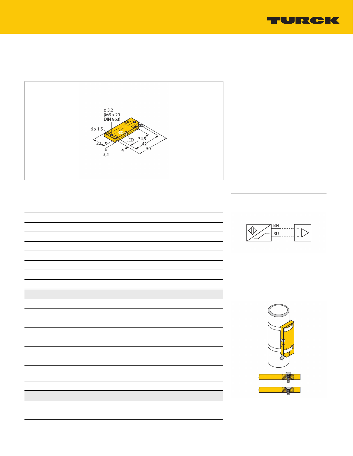
Design Rectangular,QF5,5
Dimensions 54x20.3x5.5mm
Housing material Plastic, PP
É II 1 G Ex ia IIC T6 Ga/II 1 D Ex ia IIIC
T95 °C Da
(max. Ui = 20 V, Ii = 60 mA, Pi = 80 mW)
Features
Rectangular, height 5.5 mm
■
Large active face, marked for correct
■
installation
Plastic, PP
■
Fixed settings
■
DC 2-wire, nom. 8.2 VDC
■
Output acc. to DIN EN 60947-5-6 (NAMUR)
■
Cable connection
■
ATEX category II 1 G, Ex zone 0
■
ATEX category II 1 D, Ex zone 20
■
SIL2 (Low Demand Mode) acc. to IEC
■
61508, PL c acc. to ISO 13849-1 at HFT0
SIL3 (All Demand Mode) acc. to IEC 61508,
■
PL e acc. to ISO 13849-1 with redundant
configuration HFT1
Wiring diagram
Functional principle
Capacitive proximity switches are designed
for non-contact and wear-free detection
of electrically conductive as well as nonconductive metal objects.
BC5-QF5.5-Y1X/S250 | 12/10/2020 12-35 | technical changes reserved
TURCK Inc. | 3000 Campus Drive Minneapolis, MN 55441-2656 | Phone: 763-553-7300 | Application Support: 1-800-544-7769 | Fax 763-553-0708 | www.turck.com
1|3
Page 2
Technical data
Active area material PP
Electrical connection Cable
Cable quality Ø3mm, Blue, LifYYW, PVC, 2m
Core cross-section
2x0.14mm
2
Vibration resistance 55Hz (1 mm)
Shock resistance 30g (11 ms)
Protection class IP67
MTTF 448years acc. to SN 29500 (Ed. 99) 40
°C
Switching state LED,Yellow
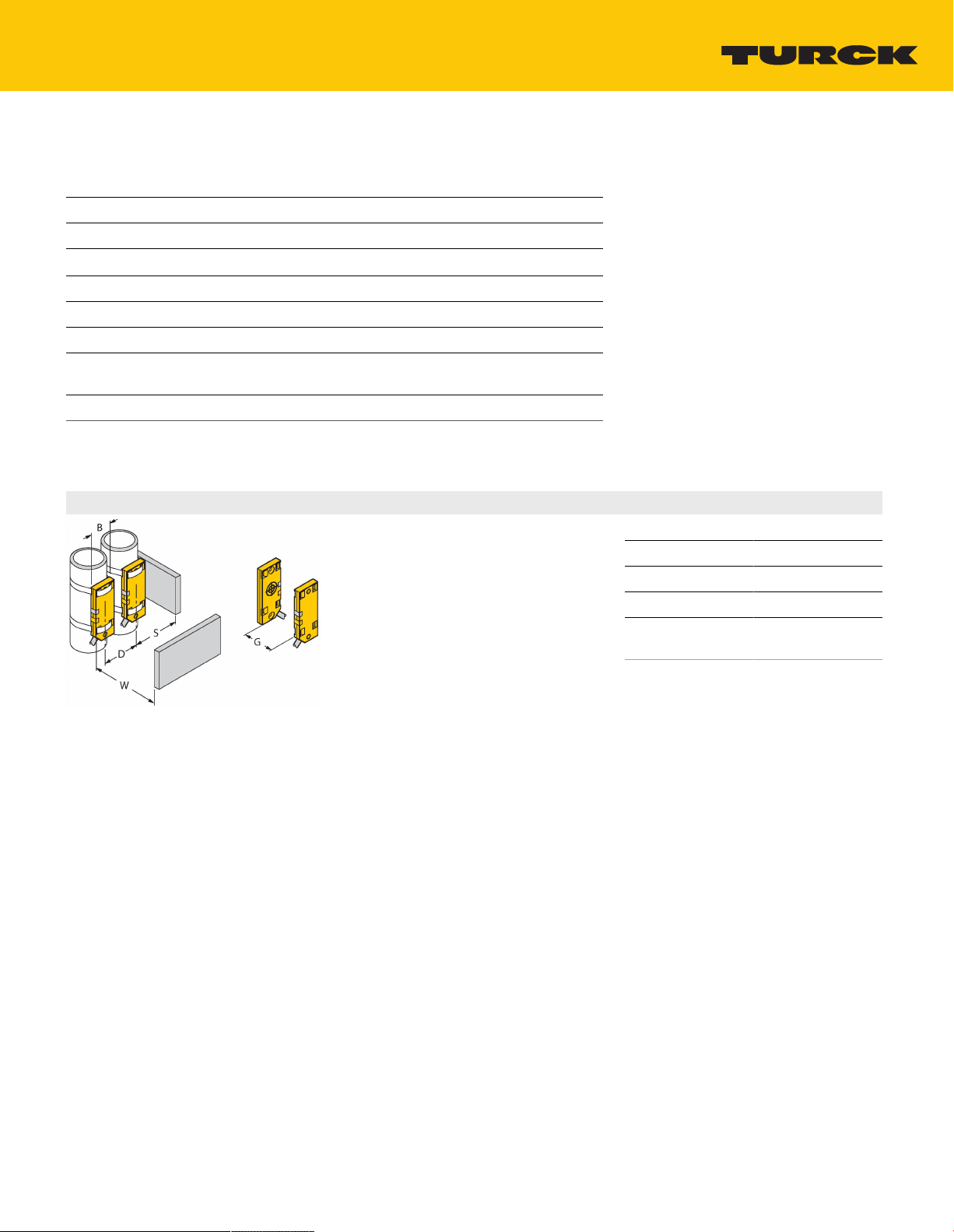
Mounting instructions
Product features
Distance D 40 mm
Distance W 30 mm
Distance S 30 mm
Distance G 60 mm
Diameter active
Ø20mm
area B
The given minimum distances have been
checked against the standard switching
distance.
Should the sensitivity of the sensors be
changed via potentiometer, the data sheet
specifications no longer apply.
TURCK Inc. | 3000 Campus Drive Minneapolis, MN 55441-2656 | Phone: 763-553-7300 | Application Support: 1-800-544-7769 | Fax 763-553-0708 | www.turck.com
BC5-QF5.5-Y1X/S250 | 12/10/2020 12-35 | technical changes reserved
2|3
Page 3

Operating Instructions
Intended use
This device fulfills the directive 2014/34/EC and is suited for use in explosion hazardous areas according to EN
60079-0:2012 + A11 and EN 60079-11:2012.Further it is suited for use in safety-related systems, including SIL2 as per IEC
61508.In order to ensure correct operation to the intended purpose it is required to observe the national regulations and
directives.
For use in explosion hazardous areas conform to classification
II 1 G and II 1 D (Group II, Category 1 G, electrical equipment for gaseous atmospheres and category 1 D, electrical equipment for
dust atmospheres).
Marking (see device or technical data sheet)
É II 1 G and Ex ia IIC T6 Ga and É II 1 D Ex ia IIIC T95 °C Da acc. to EN 60079-0, -11
Local admissible ambient temperature
-25…+70 °C
Installation/Commissioning
These devices may only be installed, connected and operated by trained and qualified staff. Qualified staff must have
knowledge of protection classes, directives and regulations concerning electrical equipment designed for use in
explosion hazardous areas.Please verify that the classification and the marking on the device comply with the actual
application conditions.
This device is only suited for connection to approved Exi circuits according to EN 60079-0 and EN 60079-11. Please
observe the maximum admissible electrical values.After connection to other circuits the sensor may no longer be
used in Exi installations. When interconnected to (associated) electrical equipment, it is required to perform the "Proof
of intrinsic safety" (EN60079-14).Attention! When used in safety systems, all content of the security manual must be
observed.
Installation and mounting instructions
Avoid static charging of cables and plastic devices. Please only clean the device with a damp cloth. Do not install the
device in a dust flow and avoid build-up of dust deposits on the device.If the devices and the cable could be subject to
mechanical damage, they must be protected accordingly. They must also be shielded against strong electro-magnetic
fields.The pin configuration and the electrical specifications can be taken from the device marking or the technical
data sheet.In order to avoid contamination of the device, please remove possible blanking plugs of the cable glands or
connectors only shortly before inserting the cable or opening the cable socket.
Service/Maintenance
Repairs are not possible. The approval expires if the device is repaired or modified by a person other than the
manufacturer. The most important data from the approval are listed.
BC5-QF5.5-Y1X/S250 | 12/10/2020 12-35 | technical changes reserved
TURCK Inc. | 3000 Campus Drive Minneapolis, MN 55441-2656 | Phone: 763-553-7300 | Application Support: 1-800-544-7769 | Fax 763-553-0708 | www.turck.com
3|3
 Loading...