

powerfast Connectivity
Application Considerations
Installation Guidelines
Turck’s Powerfast products are easy to install by following a few simple guidelines:
• It is important to know the electrical requirements of the application and
to select a cordset that has the proper amperage and voltage ratings for
the application.
• Cables must be supported to prevent movement on the equipment. Per
NFPA 79, the cable must be supported every 12 inches in a non-vertical
run, every 36 inches in a vertical run and every 18 inches when
suspended in air. The cable should also be supported at any connection
points or terminations.
Note: Consult NFPA 79 (Electrical Standard for Industrial Machinery) for required over current protection of conductors and other selection and installation guidelines
for industrial machine applications.
• The cordsets are not intended for disconnection under load. Turck
oers Powerlok ttings that prevent the possibility of disconnection
These ttings are not required for use, but can be used as a
precautionary measure.
• Power should never be supplied from the male connector. The source of
power should always be supplied from the female connector.
• Use Turck closure caps to protect connectors from damage or dirt
when not connected.
Cable Options
Turck oers multiple cable options for the Powerfast products. The
majority of Turck’s Powerfast products use cables that carry a tray
rated, exposed run (TC-ER) approval. Select Turck Powerfast
products may carry an additional STOOW cable approval, although
versions that carry the STOOW and TC-ER approval are also available
as TC-ER only.
Both the STOOW/TC-ER cable and the TC-ER only cable version are
premium cable oerings. However, the TC-ER only version has a
slightly reduced cable outer diameter. This feature oers more
exibility and is a more cost eective solution. This cable option
can be designated by adding a “/S4000” to the end of the part
description where applicable.
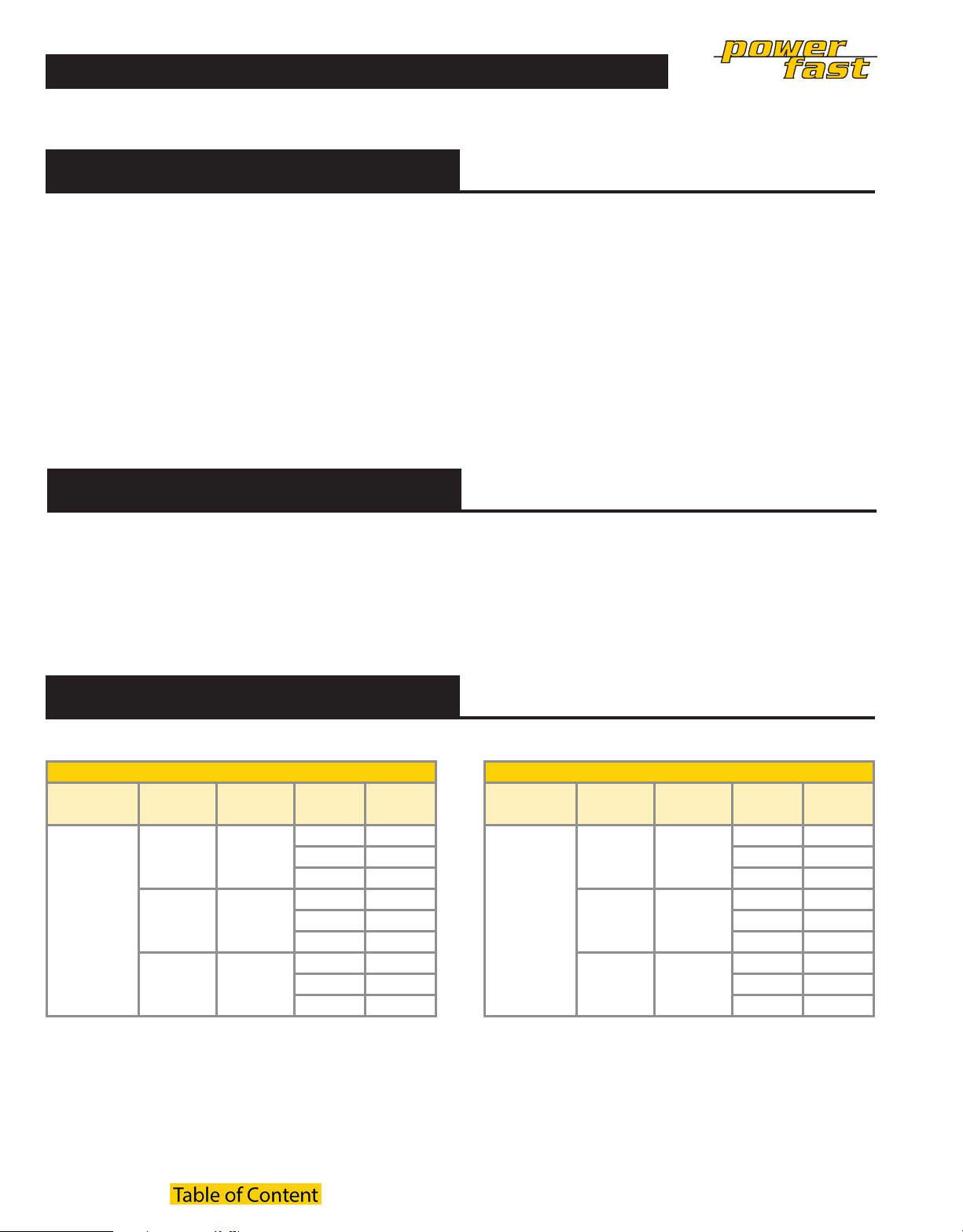
Estimated hp ratings for D-Size Powerfast
We reserve the right to make technical alterations without prior notice.
(Based on 85% motor eciency and 90% power factor.)
Single Phase (2 Current Carrying Conductors)
Pin Count AWG
10 AWG 30
3-pin
Note: These tables are theoretical values and are for reference only. Values will vary based on load conditions, as well as condition, age and type of motor.
Please consult a qualied electrician for specic product sizing requirements. Current limits for conductor gauge size taken from NFPA 79 2007 edition.
12 AWG 25
14 AWG 18
Current
(amps)
Voltage
(volts)
230 7
460 14
575 17
230 5
460 11
575 14
230 4
460 8
575 10
Power
(hp)
Three Phase (3 Current Carrying Conductors)
Pin Count AWG
10 AWG 25
4-pin
12 AWG 20
14 AWG 15
Current
(amps)
Voltage
(volts)
230 10
460 20
575 25
230 8
460 16
575 20
230 6
460 12
575 15
Power
(hp)
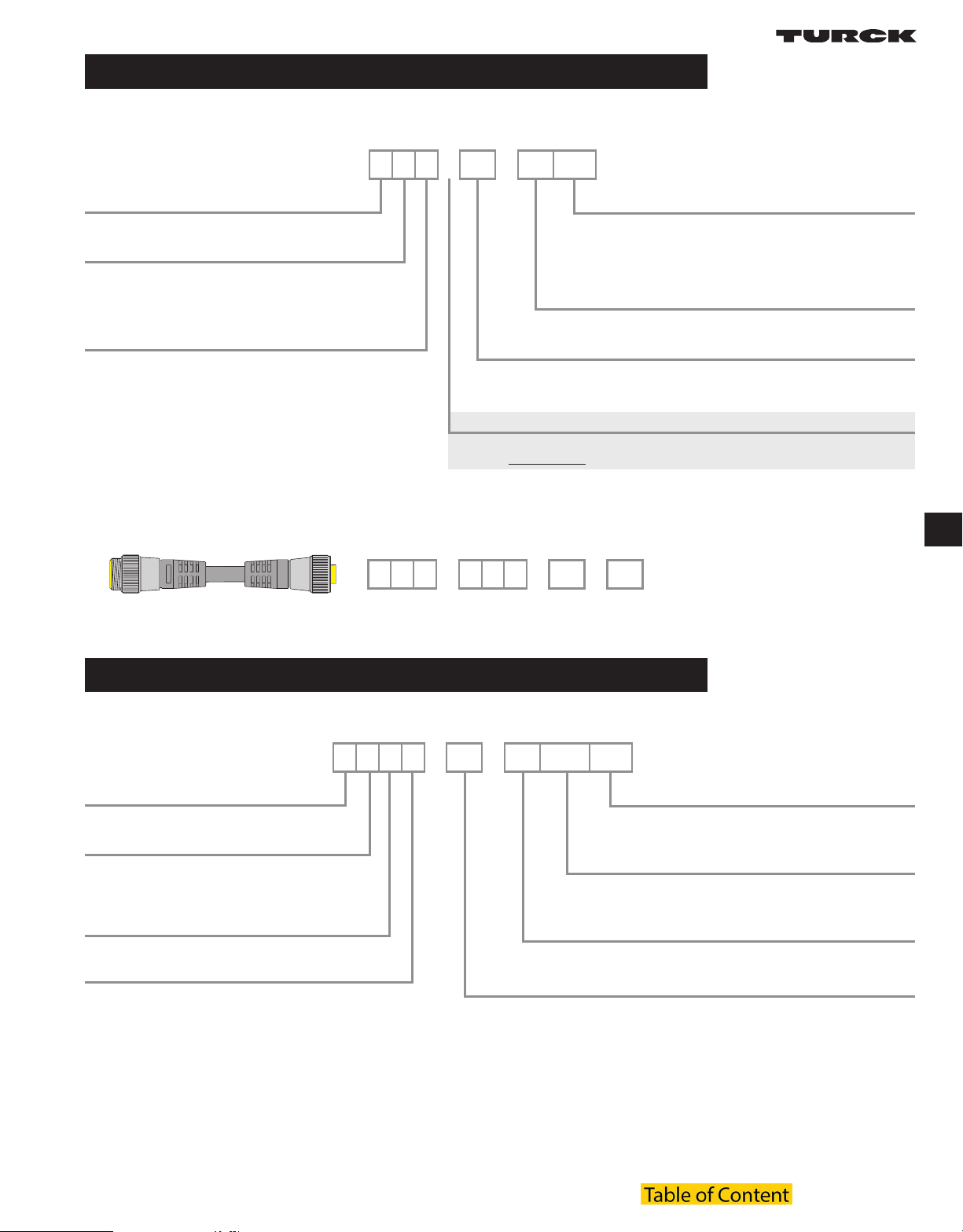
A-Size 7/8” powerfast Connectivity
2 and 3-Wire Receptacles, Front Mount, 1/4-18 NPT Threads
Part Number Keys are to assist in IDENTIFICATION ONLY. Consult factory for catalog items not identied.
R K M 34 - *M /S..
M23 Multifast® Receptacle
Gender
K = female connector, female threads
S = male connector, male threads
Y = male connector, female threads
Coupling Nut Material
(blank) = nylon
M = nickel plated brass
V = 316 stainless steel (hex)
Extension Examples
Varieties
(blank) = TC-ER STOOW PVC cable jacket
/S4000 = TC-ER PVC cable jacket
/S .. = consult factory, special
/CS .. = consult factory, special
Length in Meters
Number of Wires / AWG / Color Codes
34 = 3x14 AWG GN, BK, WH
44 = 4x14 AWG BK, WH, RD, GN
Insertion Point of Extension Cable Second Prex*
* Male connector listed rst, female connector second
Example: RSM RKM 44-2M
R S M R K M 44 - *M
A-Size 7/8” Powerfast Receptacle Part Number Key
R K F V 34 - *M /NPT /S..
A-Size 7/8” Powerfast Receptacle
Gender
K = female connector, female threads
S = male connector, male threads
X = female connector, male threads
A-Size 7/8” Powerfast Receptacle
Housing Material
(blank) = nickel plated brass
K = nylon
V = 316 stainless steel
Number of Wires / AWG / Color Codes
34 = 3x14 AWG GN, BK, WH
44 = 4x14 AWG BK, WH, RD, GN
A-Size 7/8” powerfast
Varieties
/S .. = consult factory, special
/CS .. = consult factory, special
Connection Thread
/NPT = ½-14 NPT threads
/M20 = M20 x 1.5 threads
Length in Meters
B2007 J3

A-Size 7/8” powerfast Connectivity
A-Size 7/8” Powerfast Cordset Specications
Mechanical Electrical
Mold material/color: PVC/Black
Contact carrier material: PVC Contact material: Brass or copper with gold plating
Coupling nut material: Cable jacket material/color:
Standard: Nickel plated brass Standard: TC-ER STOOW TPE/Black
Additional options: Nylon
316 stainless steel
Environmental protection: NEMA 1, 3, 4, 6P and IEC IP67 Ratings: 15 Amps, 600 VAC
Temperature rating: -40 °C to +90 °C (-40 °F to +194 °F)
A-Size 7/8” Powerfast Receptacle Part Number Key
Mechanical Electrical
Contact carrier material: PVC Contact material: Brass or copper with gold plating
Housing material/plating: Cable jacket material/color: PVC
Standard: Nickel plated brass
Additional options: Nylon
316 stainless steel
Environmental protection: NEMA 1, 3, 4, 6P and IEC IP67
Temperature rating: -40 °C to +105 °C (-40 °F to +221 °F)
Additional options: TC-ER TPE or
TC-ER PVC/Black (/S4000 version)
Ratings: 15 Amps, 600 VAC
We reserve the right to make technical alterations without prior notice.
A-Size 7/8” Powerfast Cordset Selection Matrix
1 2 3 4
Straight Female Straight Male Right Angle Female Right Angle Male
Pins AWG Current Rating TC-ER STOOW TC-ER STOOW TC-ER STOOW TC-ER STOOW
3 14 15 RKM 34-*M RSM 34-*M
4 14 15 RKM 44-*M RSM 44-*M
Pins AWG Current Rating TC-ER TC-ER TC-ER TC-ER
3 14 15 RKM 34-*M/S4000 RSM 34-*M/S4000 WKM 34-*M/S4000 WSM 34-*M/S4000
4 14 15 RKM 44-*M/S4000 RSM 44-*M/S4000 WKM 44-*M/S4000 WSM 44-*M/S4000
A-Size 7/8” Powerfast Receptacle Selection Matrix
5 6 7 8
Female Male Female Male
Pins AWG Current Rating 1/2-14 NPT Mounting Thread 1/2-14 NPT Mounting Thread M20 Mounting Thread M20 Mounting Thread
3 14 15 RKF 34-*M/NPT RSF 34-*M/NPT RSF 34-*M/M20 RKF 34-*M/M20
4 14 15 RKF 44-*M/NPT RSF 44-*M/NPT RSF 44-*M/M20 RKF 44-*M/M20
J4 B2007 www.turck.com • 1-800-544-7769 • Fax: (763) 553-0708 • Turck • Minneapolis, MN 55441 B2007 J5

1/2-14NPT
1.000 [25.4]
.650 [16.5]
1.181 [30.0]
1/2-14NPT
1.150 [29.2]
.500 [12.7]
1.000 [25.4]
1.000 [25.4]
.618 [15.7]
1.154 [29.3]
1.000 [25.4]
.618 [15.7]
1.268 [32.2]
A-Size 7/8” powerfast Connectivity
A-Size 7/8” Powerfast Cordset and Receptacle Dimensions
1 RKM.. 2 RSM..
3 WKM.. 4 WSM..
5 RKF..*/NPT.. 6 RSF..*/NPT..
Ă.988 [25.1]
7/8-16UN
Ă1.142 [29.0]
Ă.988 [25.1]
7/8-16UN
7 RKF..*/M20.. 8 RSF..*/M20..
M20x1.5
Ă.988 [25.1]
7/8-16UN
M20x1.5
Ă1.134 [28.8]
Ă.988 [25.1]
7/8-16UN
A-Size 7/8” Powerfast Cordset and Receptacle Pinouts
3-Pin Pinouts 4-Pin Pinouts
Female Male Female Male
Ă1.142 [29.0]
A-Size 7/8” powerfast
Ă1.134 [28.8]
B2007 J5
1. GN
2. BK
3. WH
1. BK
2. WH
3. RD
4. GN

A-Size 7/8” powerfast Connectivity
A-Size 7/8” Powerfast Closure Cap Selection Matrix
9 10 11 12 13 14
Mates to male
cordsets and
receptacles
Material Thread
Nickel Plated Brass 7/8-16 UN RKM-CC RSM-CC RKF-CC RSF-CC RKF-MC RSF-MC
Stainless Steel 7/8-16 UN RKMV-CC RSMV-CC RKFV-CC RSFV-CC RKFV-MC RSFV-MC
6” SS Loop
Lanyard
Mates to female
cordsets and
receptacles
6” SS Loop
Lanyard
Mates to male
receptacles
6” SS Lanyard
with Eyelet
Mates to female
receptacles
6” SS Lanyard
with Eyelet
Mates to male
cordsets and
receptacles
No Lanyard No Lanyard
A-Size 7/8” Powerfast Closure Cap Dimensions
9 RKM-CC 10 RSM-CC
Mates to female
cordsets and
receptacles
11 RKF-CC 12 RSF-CC
13 RKF-MC 14 RSF-MC
J6 B2007 www.turck.com • 1-800-544-7769 • Fax: (763) 553-0708 • Turck • Minneapolis, MN 55441 B2007 J7

A-Size 7/8” powerfast Connectivity
A-Size 7/8” Powerlok
Part Number Application A-Size Powerlok Open A-Size Powerlok Closed
LOCK-A POWER
Nylon locking guard for straight
A-Size Powerfast connectors
A-Size Powerfast Disconnect Switch Selection Matrix
We reserve the right to make technical alterations without prior notice.
Pins AWG Current Rating Standard M12 Auxilary Output
3 14 15 Amps RSF RKF 34/DS RSF RKF 34/DS/AUX
4 14 15 Amps RSF RKF 44/DS RSF RKF 44/DS/AUX
A-Size 7/8” powerfast
B2007 J7
 Loading...