

Page 1
B1N360V-Q20L60-2UP6X3-H1151/3GD
Inclinometer – With two Programmable Switching Points
Features
Rectangular, height 20 mm
■
Plastic, PC
■
Indication of operating voltage and switching
■
state
Two programmable switching outputs
■
Switchpoints selectable in a range between
■
0° and 360°
DC 4-wire, 10…30 VDC
■
M12 x 1 male connector
■
ATEX category II 3 G, Ex zone 2
■
ATEX category II 3 D, Ex zone 22
■
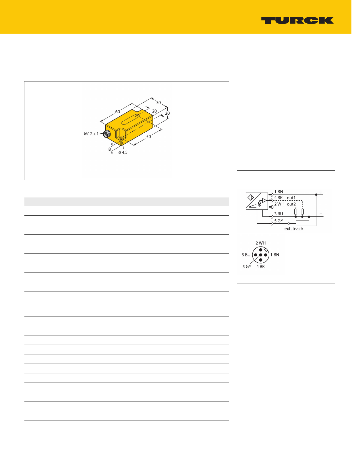
Wiring diagram
Technical data
Type
Ident. no. 1534112
Measuring range 0…360°
Number of measuring axes 1
Mounting conditions Vertical
Repeat accuracy ≤0.2% of full scale
Absolute accuracy (at 25 °C) ±0.5°
Temperature coefficient typical 0.03°/K
Resolution ≤0.14°
Ambient temperature -30…+70°C
Operating voltage 10…30VDC
Residual ripple ≤10% U
Residual current ≤0.1mA
Isolation test voltage ≤0.5kV
Output current ≤500mA
Response delay 500ms
Dropout delay 350ms
Short-circuit protection yes / Thermal
Wire breakage/Reverse polarity protection yes / Complete
Output function 5-pin, NO/NC, 2 × PNP
Current consumption 35 mA
B1N360V-Q20L60-2UP6X3-H1151/3GD
For explosion hazardous areas see
instruction leaflet
ss
Surge protection from +Ub to (Ub - 40V)
Functional principle
Inclination is determined by a wear-free
semiconducting sensor element.
B1N360V-Q20L60-2UP6X3-H1151/3GD | 12/03/2020 07-32 | technical changes reserved
TURCK Inc. | 3000 Campus Drive Minneapolis, MN 55441-2656 | Phone: 763-553-7300 | Application Support: 1-800-544-7769 | Fax 763-553-0708 | www.turck.com
1|6
Page 2
Technical data
Approval acc. to ATEX declaration of conformity TURCK
Ex-12003H X
Device marking Ex II 3 G Ex nA IIC T5 Gc/II 3 D Ex tc IIIC
T85°C Dc
Design
Dimensions 60x30x20mm
Housing material Plastic, PC
Electrical connection Connector,M12 × 1
Vibration resistance 55Hz (1 mm)
Shock resistance 30g (11 ms)
Protection class IP68 / IP69K
MTTF 399years acc. to SN 29500 (Ed. 99) 40
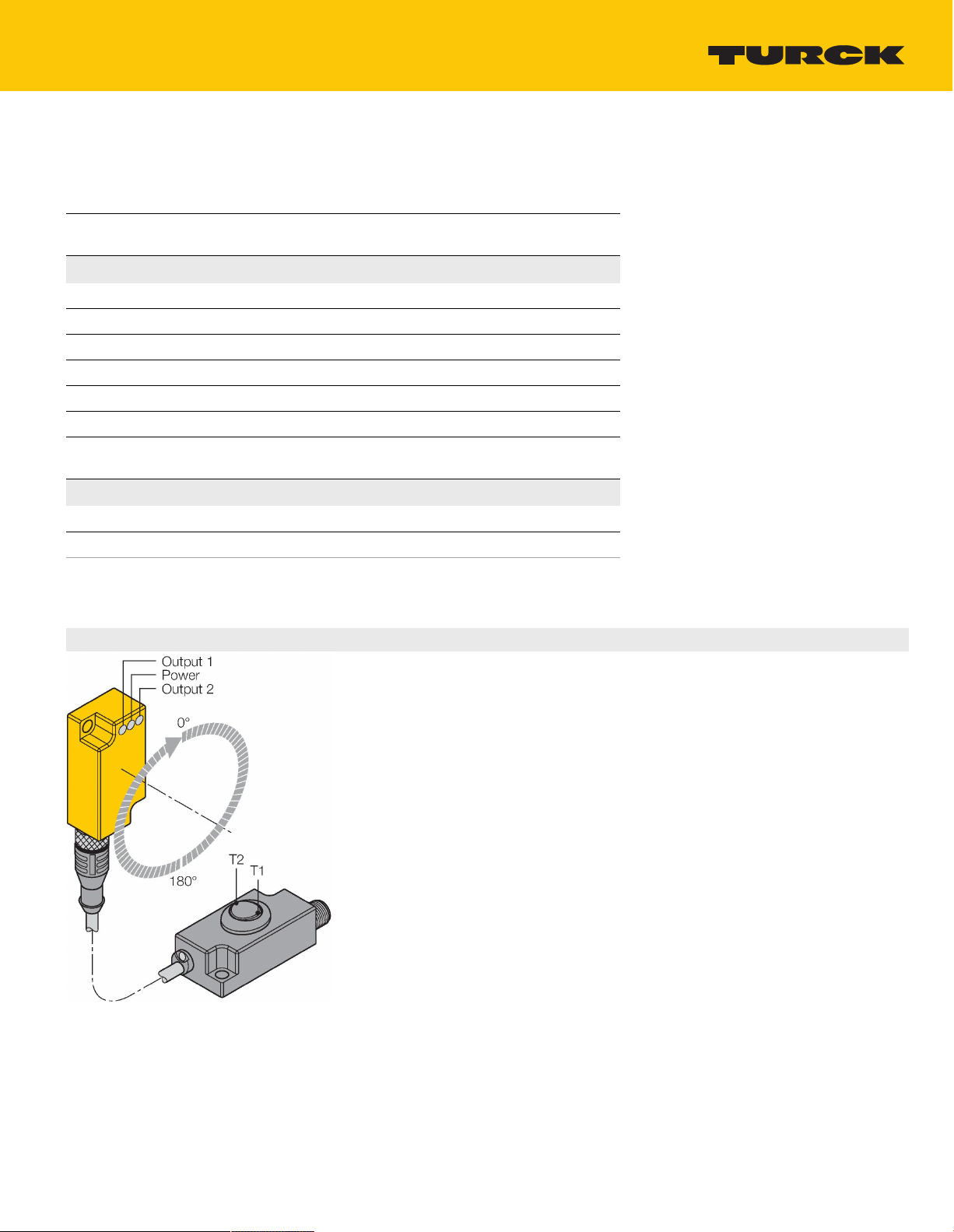
Power-on indication
Switching state 2 × LEDs,Yellow
Included in delivery Security clip SC-M12/3GD, SC-M12/3GD
Rectangular,Q20L60
°C
LED,Green
Mounting instructions
Mounting instructions/Description
The switchpoints are set with the TX1-Q20L60
teach adapter
By actuating the toggle switch T1 (OUT 1), a
bridge is formed between GND and pin 5.
By actuating the toggle switch T2 (OUT 2), a
bridge is formed between UB and pin 5.
The switch-on and off points are freely
selectable within 360° degrees.
You can teach-in the switching points either
clockwise or counter-clockwise.
Before programming the wanted switch-on and
off points, move the sensor in start position. For
details on programming, please see next page.
Should you wish to set the switch-off point
yourself, the sensor must also be positioned
at this point. The sensor must be installed in
vertical position.
A further programming method has already a
preset range of 180°. Here, only the switch-on
point must be set.
TURCK Inc. | 3000 Campus Drive Minneapolis, MN 55441-2656 | Phone: 763-553-7300 | Application Support: 1-800-544-7769 | Fax 763-553-0708 | www.turck.com
B1N360V-Q20L60-2UP6X3-H1151/3GD | 12/03/2020 07-32 | technical changes reserved
2|6
Page 3

Accessories
GUARD-Q20L60 A9684
Protective housing for Q20L60
inclinometers for protecting against
mechanical impact; material:
Stainless steel
TURCK Inc. | 3000 Campus Drive Minneapolis, MN 55441-2656 | Phone: 763-553-7300 | Application Support: 1-800-544-7769 | Fax 763-553-0708 | www.turck.com
B1N360V-Q20L60-2UP6X3-H1151/3GD | 12/03/2020 07-32 | technical changes reserved
3|6
Page 4

Operating Instructions
Switchpoint adjustable as NO contact counter-clockwise or as NC contact clockwise
Press T1 (T2) for 5 s
Power LED flashes
Place the sensor in the wanted start position
Press T1 (T2) for 1 s to set the switch-on point
Power LED and Output 1 (2) LED flash
Place the sensor in the wanted end position
Press T1 (T2) for 3 s to set the switch-off point
Power LED and Output 1 (2) LED flash for 3 s then turn steady
Teach process completed, sensor ready for operation.
Switchpoint adjustable as NO contact clockwise or as NC contact counter-clockwise
Press T1 (T2) for 5 s
Power LED flashes
Place the sensor in the wanted start position
Press T1 (T2) for 3 s to set the switch-on point
Power LED and Output 1 (2) LED flash fast
Place the sensor in the wanted end position
Press T1 (T2) for 1 s to set the switch-off point
Power LED and Output 1 (2) LED flash for 3 s then turn steady
Teach process completed, sensor ready for operation.
Switchpoint adjustable as NO contact counter-clockwise or as NC contact clockwise (180° default
setting)
Press T1 (T2) for 5 s
Power LED flashes
Place the sensor in the wanted start position
Press T1 (T2) for 1 s to set the switch-on point
Power LED and Output 1 (2) LED flash
Press T1 (T2) for 1 s to set the travel path 180 ° and the hysteresis 1 °
Power LED and Output 1 (2) LED flash for 3 s then turn steady
Teach process completed, sensor ready for operation.
Switchpoint adjustable as NO contact clockwise or as NC contact counter-clockwise (180° default
setting)
Press T1 (T2) for 5 s
Power LED flashes
Place the sensor in the wanted start position
Press T1 (T2) for 3 s to set the switch-on point
Power LED and Output 1 (2) LED flash fast
Press T1 (T2) for 3 s to set the travel path 180 ° and the hysteresis 1 °
Power LED and Output 1 (2) LED flash for 3 s then turn steady
Teach process completed, sensor ready for operation.
T1 = Switching output 1; T2 = Switching output 2
Default settings:
Hysteresis 1°
Intended use
B1N360V-Q20L60-2UP6X3-H1151/3GD | 12/03/2020 07-32 | technical changes reserved
TURCK Inc. | 3000 Campus Drive Minneapolis, MN 55441-2656 | Phone: 763-553-7300 | Application Support: 1-800-544-7769 | Fax 763-553-0708 | www.turck.com
4|6
Page 5

This device fulfills the directive 2014/34/EC and is suited for use in explosion hazardous areas according to
EN60079-0:2009, EN60079-15:2010 and EN60079-31:2009In order to ensure correct operation to the intended purpose it is
required to observe the national regulations and directives.
For use in explosion hazardous areas conform to classification
II 3 G and II 3 D (Group II, Category 3 G, electrical equipment for gaseous atmospheres and category 3 D, electrical equipment for
dust atmospheres).
Marking (see device or technical data sheet)
Ex II 3 G Ex nA IIC T5 Gc acc .to EN 60079-0:2009 and EN 60079-15:2010 and Ex II 3 D Ex tc IIIC T85°C Dc acc. to EN
60079-0:2009 and EN 60079-31:2009
Local admissible ambient temperature
-30…+70 °C
Installation/Commissioning
These devices may only be installed, connected and operated by trained and qualified staff. Qualified staff must have
knowledge of protection classes, directives and regulations concerning electrical equipment designed for use in
explosion hazardous areas.Please verify that the classification and the marking on the device comply with the actual
application conditions.
Installation and mounting instructions
Avoid static charging of cables and plastic devices. Please only clean the device with a damp cloth. Do not install the
device in a dust flow and avoid build-up of dust deposits on the device.If the devices and the cable could be subject to
mechanical damage, they must be protected accordingly. They must also be shielded against strong electro-magnetic
fields.The pin configuration and the electrical specifications can be taken from the device marking or the technical
data sheet.In order to avoid contamination of the device, please remove possible blanking plugs of the cable glands or
connectors only shortly before inserting the cable or opening the cable socket.
Special conditions for safe operation
For devices with M12 connectors please use the supplied safety clip SC-M12/3GD. The safety clips SC-M12/3GD are
not required when using the protective housing SG-Q20L60.Do not disconnect the plug-in connection or cable under
voltage.Please attach a warning label permanently in an appropriate fashion in close proximity to the plug-in connection
with the following inscription: Nicht unter Spannung trennen / Do not separate when energized.The device must be
protected against any kind of mechanical damage and degrading UV-radiation. On selecting the approval-relevant
accessories, always ensure that they are installed conform to the application.Load voltage and operating voltage of this
equipment must be supplied from power supplies with safe isolation (IEC 30 364/UL508), to ensure that the rated voltage
of the equipment (24 VDC +20% = 28.8 VDC) is never exceeded by more than 40%.
Service/Maintenance
Repairs are not possible. The approval expires if the device is repaired or modified by a person other than the
manufacturer. The most important data from the approval are listed.
Operating Instructions
Switchpoint adjustable as NO contact counter-clockwise or as NC contact clockwise
Press T1 (T2) for 5 s
Power LED flashes
Place the sensor in the wanted start position
Press T1 (T2) for 1 s to set the switch-on point
Power LED and Output 1 (2) LED flash
Place the sensor in the wanted end position
Press T1 (T2) for 3 s to set the switch-off point
Power LED and Output 1 (2) LED flash for 3 s then turn steady
Teach process completed, sensor ready for operation.
Switchpoint adjustable as NO contact clockwise or as NC contact counter-clockwise
Press T1 (T2) for 5 s
Power LED flashes
B1N360V-Q20L60-2UP6X3-H1151/3GD | 12/03/2020 07-32 | technical changes reserved
TURCK Inc. | 3000 Campus Drive Minneapolis, MN 55441-2656 | Phone: 763-553-7300 | Application Support: 1-800-544-7769 | Fax 763-553-0708 | www.turck.com
5|6
Page 6

Place the sensor in the wanted start position
Press T1 (T2) for 3 s to set the switch-on point
Power LED and Output 1 (2) LED flash fast
Place the sensor in the wanted end position
Press T1 (T2) for 1 s to set the switch-off point
Power LED and Output 1 (2) LED flash for 3 s then turn steady
Teach process completed, sensor ready for operation.
Switchpoint adjustable as NO contact counter-clockwise or as NC contact clockwise (180° default setting)
Press T1 (T2) for 5 s
Power LED flashes
Place the sensor in the wanted start position
Press T1 (T2) for 1 s to set the switch-on point
Power LED and Output 1 (2) LED flash
Press T1 (T2) for 1 s to set the travel path 180 ° and the hysteresis 1 °
Power LED and Output 1 (2) LED flash for 3 s then turn steady
Teach process completed, sensor ready for operation.
Switchpoint adjustable as NO contact clockwise or as NC contact counter-clockwise (180° default setting)
Press T1 (T2) for 5 s
Power LED flashes
Place the sensor in the wanted start position
Press T1 (T2) for 3 s to set the switch-on point
Power LED and Output 1 (2) LED flash fast
Press T1 (T2) for 3 s to set the travel path 180 ° and the hysteresis 1 °
Power LED and Output 1 (2) LED flash for 3 s then turn steady
Teach process completed, sensor ready for operation.
T1 = Switching output 1; T2 = Switching output 2
Default settings:
Hysteresis 1°
TURCK Inc. | 3000 Campus Drive Minneapolis, MN 55441-2656 | Phone: 763-553-7300 | Application Support: 1-800-544-7769 | Fax 763-553-0708 | www.turck.com
B1N360V-Q20L60-2UP6X3-H1151/3GD | 12/03/2020 07-32 | technical changes reserved
6|6
 Loading...