

Page 1
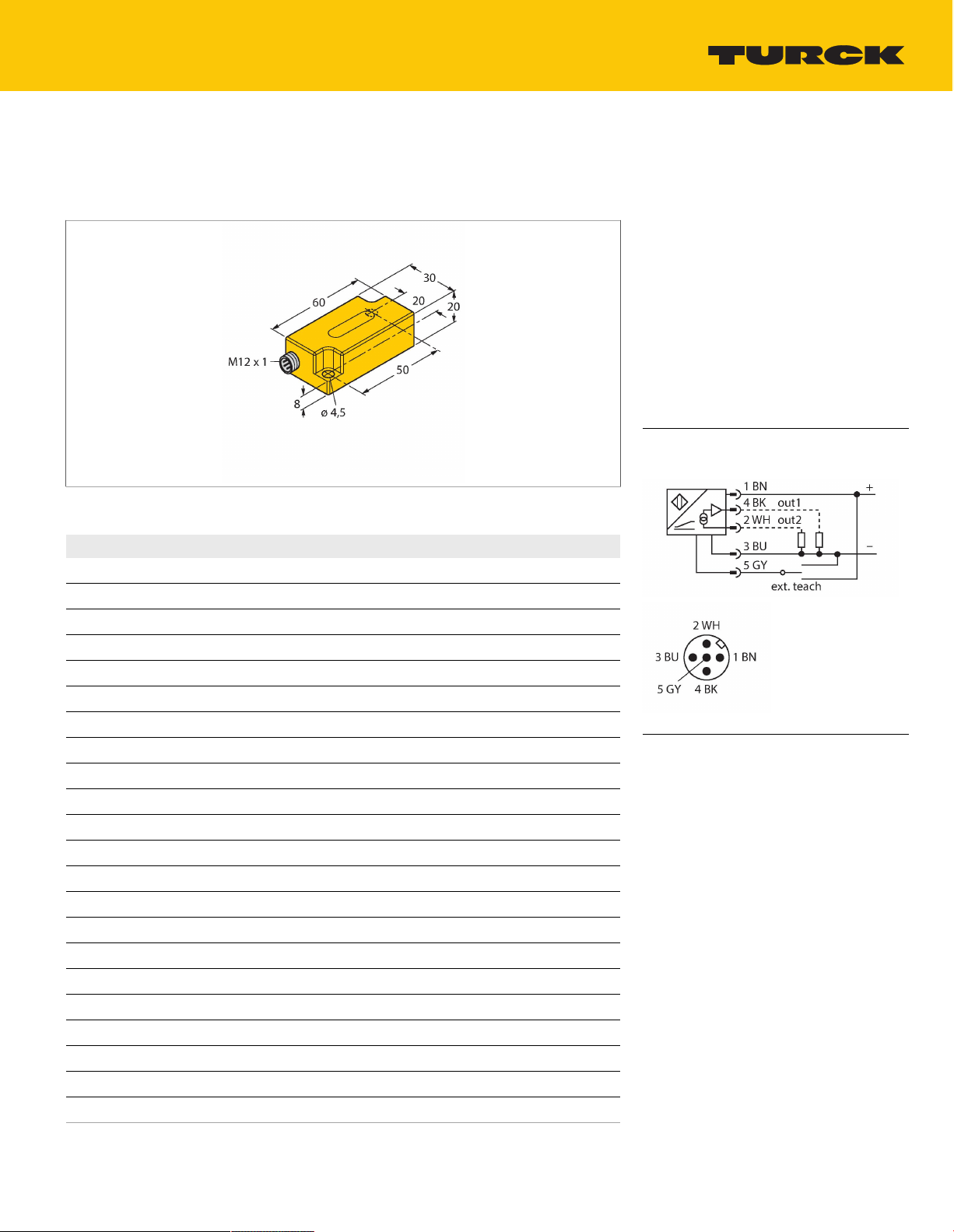
B1N360V-Q20L60-2UP6X3-H1151
Inclinometer – With two Programmable Switching Points
Features
Rectangular, height 20 mm
■
Plastic, PC
■
Indication of operating voltage and switching
■
state
Two programmable switching outputs
■
Switchpoints selectable in a range between
■
0° and 360°
DC 4-wire, 10…30 VDC
■
M12 x 1 male connector
■
Wiring diagram
Technical data
Type
Ident. no. 1534051
Measuring range 0…360°
measuring range z-axis 0…360°
Number of measuring axes 1
Mounting conditions Vertical
Repeat accuracy ≤0.2% of full scale
Absolute accuracy (at 25 °C) ±0.5°
Temperature coefficient typical 0.03°/K
Resolution ≤0.14°
Ambient temperature -30…+70°C
Operating voltage 10…30VDC
Residual ripple ≤10% U
Residual current ≤0.1mA
Isolation test voltage ≤0.5kV
Output current ≤500mA
Response delay 500ms
Dropout delay 350ms
Short-circuit protection yes / Thermal
Wire breakage/Reverse polarity protection yes / Complete
Output function 5-pin, NO/NC, 2 × PNP
Current consumption 35 mA
B1N360V-Q20L60-2UP6X3-H1151
ss
Surge protection from +Ub to (Ub - 40V)
Functional principle
Inclination is determined by a wear-free
semiconducting sensor element.
TURCK Inc. | 3000 Campus Drive Minneapolis, MN 55441-2656 | Phone: 763-553-7300 | Application Support: 1-800-544-7769 | Fax 763-553-0708 | www.turck.com
B1N360V-Q20L60-2UP6X3-H1151 | 12/03/2020 07-30 | technical changes reserved
1|4
Page 2
Technical data
Design
Rectangular,Q20L60
Dimensions 60x30x20mm
Housing material Plastic, PC
Electrical connection Connector,M12 × 1
Vibration resistance 55Hz (1 mm)
Shock resistance 30g (11 ms)
Protection class IP68 / IP69K
MTTF 399years acc. to SN 29500 (Ed. 99) 40
°C
Power-on indication
LED,Green
Switching state 2 × LEDs,Yellow
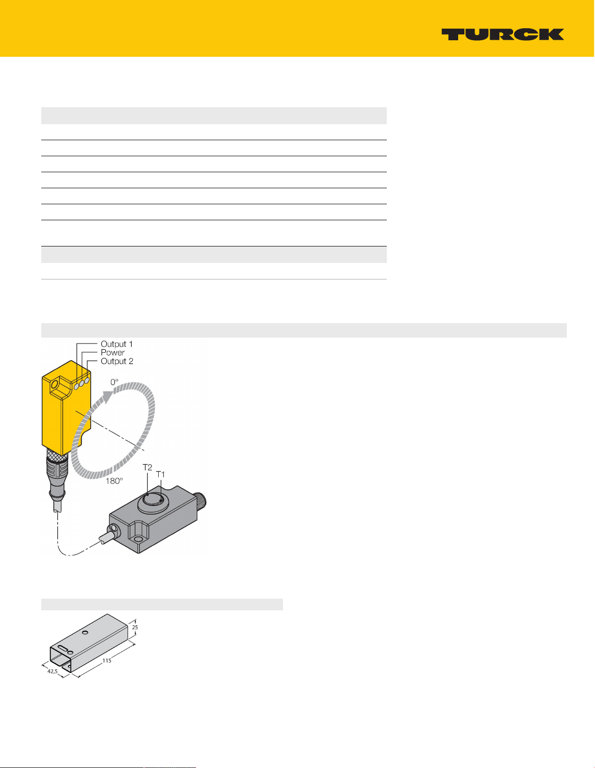
Mounting instructions
Mounting instructions/Description
The switchpoints are set with the TX1-Q20L60
teach adapter
By actuating the toggle switch T1 (OUT 1), a
bridge is formed between GND and pin 5.
By actuating the toggle switch T2 (OUT 2), a
bridge is formed between UB and pin 5.
The switch-on and off points are freely
selectable within 360° degrees.
You can teach-in the switching points either
clockwise or counter-clockwise.
Before programming the wanted switch-on and
off points, move the sensor in start position. For
details on programming, please see next page.
Should you wish to set the switch-off point
yourself, the sensor must also be positioned
at this point. The sensor must be installed in
vertical position.
A further programming method has already a
preset range of 180°. Here, only the switch-on
point must be set.
Accessories
GUARD-Q20L60 A9684
Protective housing for Q20L60
inclinometers for protecting against
mechanical impact; material:
Stainless steel
TURCK Inc. | 3000 Campus Drive Minneapolis, MN 55441-2656 | Phone: 763-553-7300 | Application Support: 1-800-544-7769 | Fax 763-553-0708 | www.turck.com
B1N360V-Q20L60-2UP6X3-H1151 | 12/03/2020 07-30 | technical changes reserved
2|4
Page 3

Operating Instructions
Switchpoint adjustable as NO contact counter-clockwise or as NC contact clockwise
Press T1 (T2) for 5 s
Power LED flashes
Place the sensor in the wanted start position
Press T1 (T2) for 1 s to set the switch-on point
Power LED and Output 1 (2) LED flash
Place the sensor in the wanted end position
Press T1 (T2) for 3 s to set the switch-off point
Power LED and Output 1 (2) LED flash for 3 s then turn steady
Teach process completed, sensor ready for operation.
Switchpoint adjustable as NO contact clockwise or as NC contact counter-clockwise
Press T1 (T2) for 5 s
Power LED flashes
Place the sensor in the wanted start position
Press T1 (T2) for 3 s to set the switch-on point
Power LED and Output 1 (2) LED flash fast
Place the sensor in the wanted end position
Press T1 (T2) for 1 s to set the switch-off point
Power LED and Output 1 (2) LED flash for 3 s then turn steady
Teach process completed, sensor ready for operation.
Switchpoint adjustable as NO contact counter-clockwise or as NC contact clockwise (180° default
setting)
Press T1 (T2) for 5 s
Power LED flashes
Place the sensor in the wanted start position
Press T1 (T2) for 1 s to set the switch-on point
Power LED and Output 1 (2) LED flash
Press T1 (T2) for 1 s to set the travel path 180 ° and the hysteresis 1 °
Power LED and Output 1 (2) LED flash for 3 s then turn steady
Teach process completed, sensor ready for operation.
Switchpoint adjustable as NO contact clockwise or as NC contact counter-clockwise (180° default
setting)
Press T1 (T2) for 5 s
Power LED flashes
Place the sensor in the wanted start position
Press T1 (T2) for 3 s to set the switch-on point
Power LED and Output 1 (2) LED flash fast
Press T1 (T2) for 3 s to set the travel path 180 ° and the hysteresis 1 °
Power LED and Output 1 (2) LED flash for 3 s then turn steady
Teach process completed, sensor ready for operation.
T1 = Switching output 1; T2 = Switching output 2
Default settings:
Hysteresis 1°
Operating Instructions
B1N360V-Q20L60-2UP6X3-H1151 | 12/03/2020 07-30 | technical changes reserved
TURCK Inc. | 3000 Campus Drive Minneapolis, MN 55441-2656 | Phone: 763-553-7300 | Application Support: 1-800-544-7769 | Fax 763-553-0708 | www.turck.com
3|4
Page 4

Switchpoint adjustable as NO contact counter-clockwise or as NC contact clockwise
Press T1 (T2) for 5 s
Power LED flashes
Place the sensor in the wanted start position
Press T1 (T2) for 1 s to set the switch-on point
Power LED and Output 1 (2) LED flash
Place the sensor in the wanted end position
Press T1 (T2) for 3 s to set the switch-off point
Power LED and Output 1 (2) LED flash for 3 s then turn steady
Teach process completed, sensor ready for operation.
Switchpoint adjustable as NO contact clockwise or as NC contact counter-clockwise
Press T1 (T2) for 5 s
Power LED flashes
Place the sensor in the wanted start position
Press T1 (T2) for 3 s to set the switch-on point
Power LED and Output 1 (2) LED flash fast
Place the sensor in the wanted end position
Press T1 (T2) for 1 s to set the switch-off point
Power LED and Output 1 (2) LED flash for 3 s then turn steady
Teach process completed, sensor ready for operation.
Switchpoint adjustable as NO contact counter-clockwise or as NC contact clockwise (180° default setting)
Press T1 (T2) for 5 s
Power LED flashes
Place the sensor in the wanted start position
Press T1 (T2) for 1 s to set the switch-on point
Power LED and Output 1 (2) LED flash
Press T1 (T2) for 1 s to set the travel path 180 ° and the hysteresis 1 °
Power LED and Output 1 (2) LED flash for 3 s then turn steady
Teach process completed, sensor ready for operation.
Switchpoint adjustable as NO contact clockwise or as NC contact counter-clockwise (180° default setting)
Press T1 (T2) for 5 s
Power LED flashes
Place the sensor in the wanted start position
Press T1 (T2) for 3 s to set the switch-on point
Power LED and Output 1 (2) LED flash fast
Press T1 (T2) for 3 s to set the travel path 180 ° and the hysteresis 1 °
Power LED and Output 1 (2) LED flash for 3 s then turn steady
Teach process completed, sensor ready for operation.
T1 = Switching output 1; T2 = Switching output 2
Default settings:
Hysteresis 1°
TURCK Inc. | 3000 Campus Drive Minneapolis, MN 55441-2656 | Phone: 763-553-7300 | Application Support: 1-800-544-7769 | Fax 763-553-0708 | www.turck.com
B1N360V-Q20L60-2UP6X3-H1151 | 12/03/2020 07-30 | technical changes reserved
4|4
 Loading...