

Page 1

Page 1 of 23
Turbovex A/S
Industrivej 45, DK – 9600 Aars
Tel: +45 96 98 14 62 – Fax: +45 98 96 42 24
e-mail: [email protected] – www.turbovex.dk
Installation, operation and
maintenance guide
for window models
Rev. 2014.06.25
Page 2

Page 2 of 23
Turbovex A/S
Industrivej 45, DK – 9600 Aars
Tel: +45 96 98 14 62 – Fax: +45 98 96 42 24
e-mail: [email protected] – www.turbovex.dk
Table of content
2.0.0 GENERAL INFORMATION...................................................................................................................... 3
2.1.0 P
REFACE
................................................................................................................................................ 3
2.2.0 A
REAS OF USE
........................................................................................................................................ 3
2.3.0 I
NCORRECT USE
...................................................................................................................................... 3
2.4.0 S
COPE OF DELIVERY
............................................................................................................................... 3
2.5.0 M
AIN COMPONENTS
: ............................................................................................................................... 4
F
IGURE 2: MAIN COMPONENTS
......................................................................................................................... 4
F
IGURE 3 MAIN COMPONENTS
.......................................................................................................................... 5
3.0.0 INSTALLATION OF UNIT ........................................................................................................................ 6
3.1.0. E
XTERNAL DIMENSIONS
.......................................................................................................................... 6
3.2.0 W
ALL/WINDOW INSTALLATION
.................................................................................................................. 7
4.0.0 PLACING THE UNIT .............................................................................................................................. 11
PLACING THE UNIT (CONT.) ........................................................................................................................ 12
5.0.0 SERVICE ................................................................................................................................................ 13
5.1.0 F
ILTER CHANGE
.................................................................................................................................... 13
5.2.0 R
EMOVING FILTERS AND EXCHANGER
..................................................................................................... 14
6.0.0 CONNECTING MAINS ELECTRICITY .................................................................................................. 17
6.1.0 C
ONNECTION
........................................................................................................................................ 17
6.2.0 W
IRING DIAGRAM
.................................................................................................................................. 18
7.0.0 TECHNICAL SPECIFICATIONS............................................................................................................ 19
7.1.0 S
OUND TEST
......................................................................................................................................... 20
8.0.0 PRINCIPLE OF OPERATION ................................................................................................................ 21
8.1.0 D
ESCRIPTION
....................................................................................................................................... 21
9.0.0 OPERATION .......................................................................................................................................... 22
9.1.0 R
EGULATING AIR VOLUME
...................................................................................................................... 22
9.2.0 R
EGULATING WARMTH
........................................................................................................................... 22
9.3.0 M
ASTER/SLAVE
..................................................................................................................................... 22
10.0.0 DECLARATION OF COMPLIANCE .................................................................................................... 23
Page 3
Page 3 of 23
Turbovex A/S
Industrivej 45, DK – 9600 Aars
Tel: +45 96 98 14 62 – Fax: +45 98 96 42 24
e-mail: [email protected] – www.turbovex.dk
2.0.0 General information
Turbovex TX 350A and TX 75A are decentralized ventilation units with integrated heat
recovery.
2.1.0 Preface
This installation and operation guide contains technical information and details of
installation and maintenance of the unit.
2.2.0 Areas of use
Window models are designed for comfort ventilation for institutions, canteens, offices and
conference rooms etc.
2.3.0 Incorrect use
The window models are not designed for local exhaust ventilation, and are therefore not
suitable for this purpose.
2.4.0 Scope of delivery
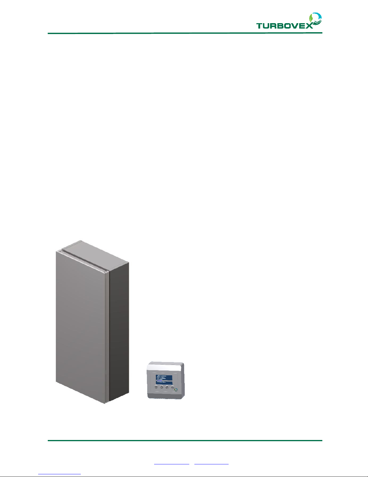
TX window models are supplied with the following main components:
1. Turbovex TX window model
2. TX electronic controller
Figure 1 Deliverables
Page 4
Page 4 of 23
Turbovex A/S
Industrivej 45, DK – 9600 Aars
Tel: +45 96 98 14 62 – Fax: +45 98 96 42 24
e-mail: [email protected] – www.turbovex.dk
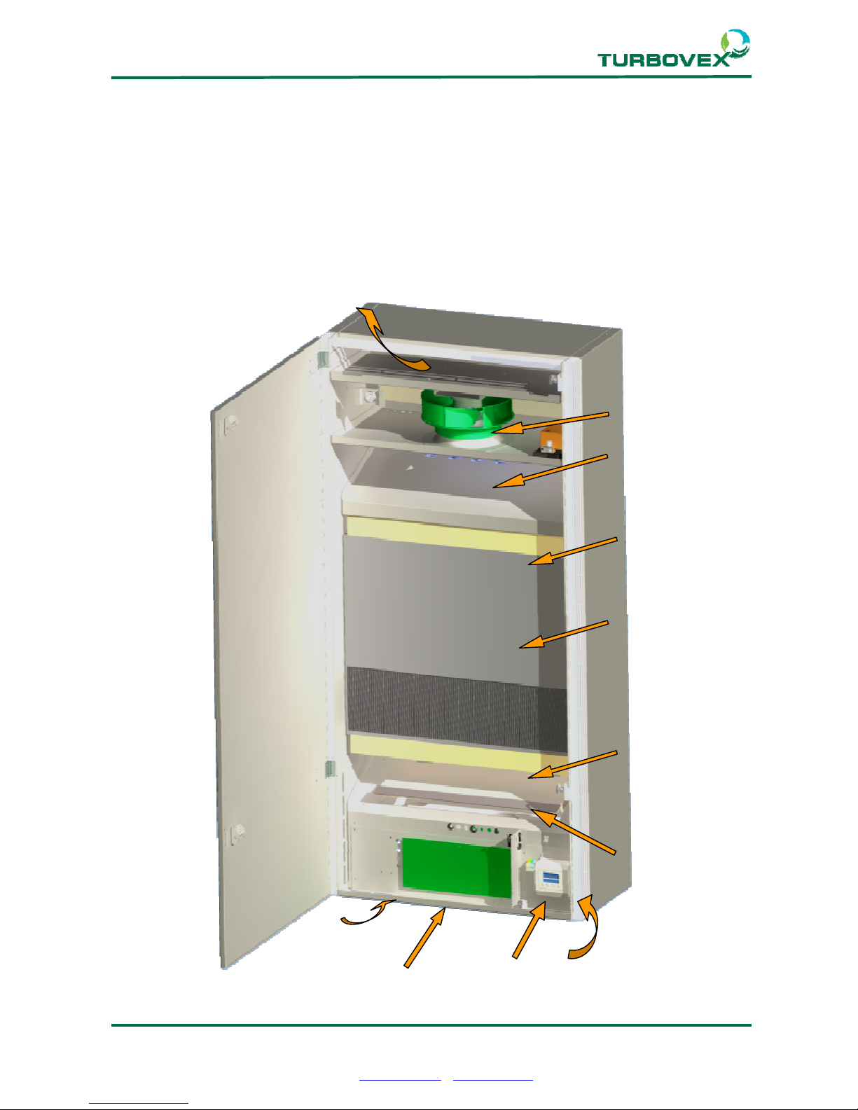
2.5.0 Main components:
Figure 2: Main components
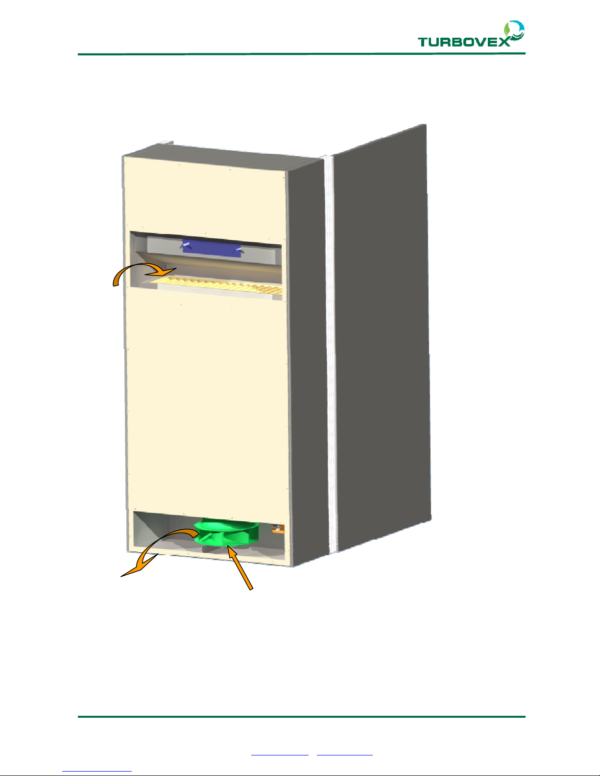
1. Intake Air
2. Exhaust Air
3. Extract Air
4. Supply Air
5. Counterflow heat exchanger
6. Supply Air Fan
7. Extract Air Fan
8. Bypass Damper
9. Electrical heater
10. Filter
11. Main PCB
12. TX Controller
11
3
4
5
6
9
10
8
10
12
3
Page 5
Page 5 of 23
Turbovex A/S
Industrivej 45, DK – 9600 Aars
Tel: +45 96 98 14 62 – Fax: +45 98 96 42 24
e-mail: [email protected] – www.turbovex.dk
Figure 3 Main components
1
2
7
Page 6
Page 6 of 23
Turbovex A/S
Industrivej 45, DK – 9600 Aars
Tel: +45 96 98 14 62 – Fax: +45 98 96 42 24
e-mail: [email protected] – www.turbovex.dk
3.0.0 Installation of unit
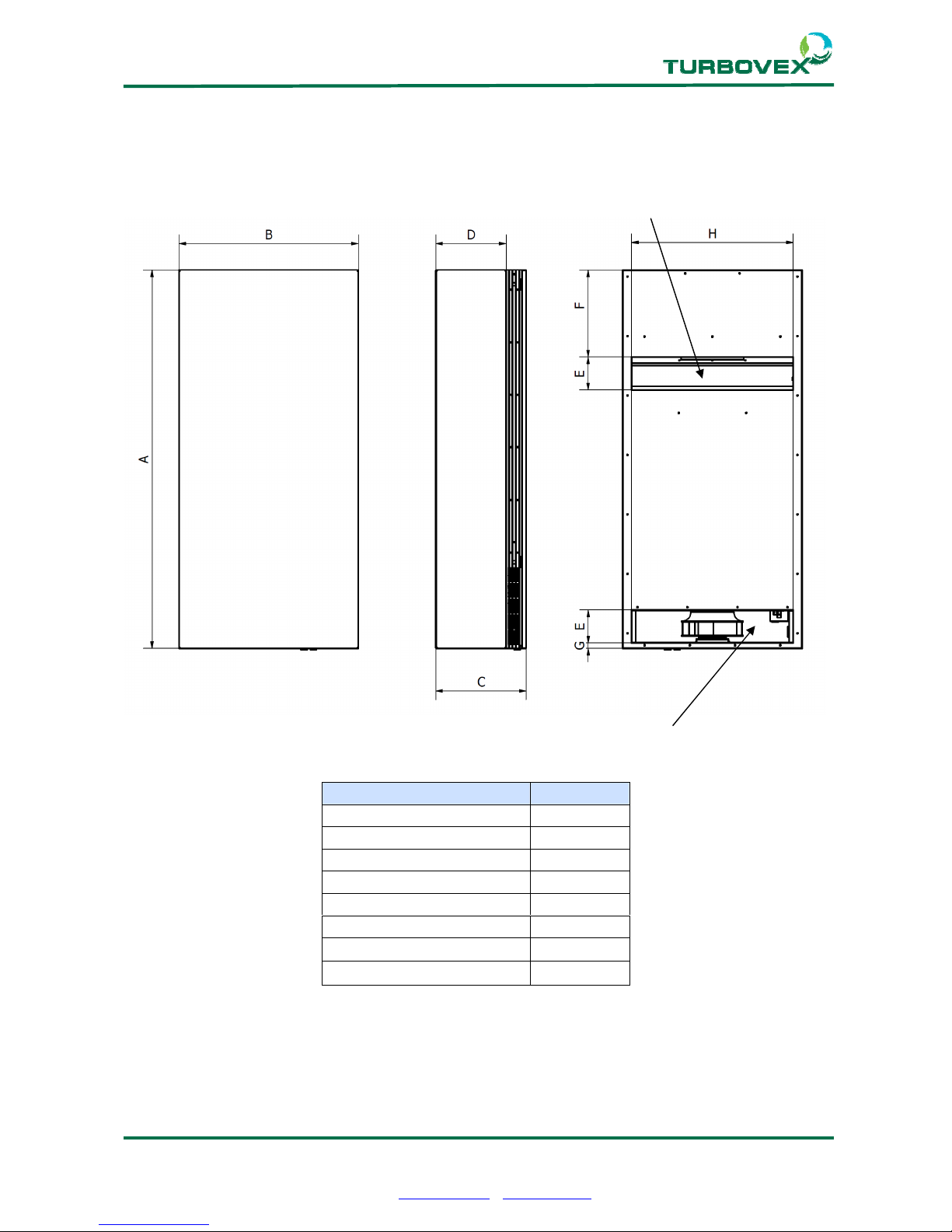
3.1.0. External dimensions
Intake zone
Minimum required distance to walls, floor and ceiling is 70 mm.
Dimensions (mm) TX350A
A (Height) 1400
B (Width) 662
C (Depth) 334
D (Mounting Dimension) 260
E (Hole Height) 122
F (Hole Distance Upper) 322
G (Hole Distance Lower) 20
H (Hole Width) 597
Exhaust Zone
Page 7
Page 7 of 23
Turbovex A/S
Industrivej 45, DK – 9600 Aars
Tel: +45 96 98 14 62 – Fax: +45 98 96 42 24
e-mail: [email protected] – www.turbovex.dk
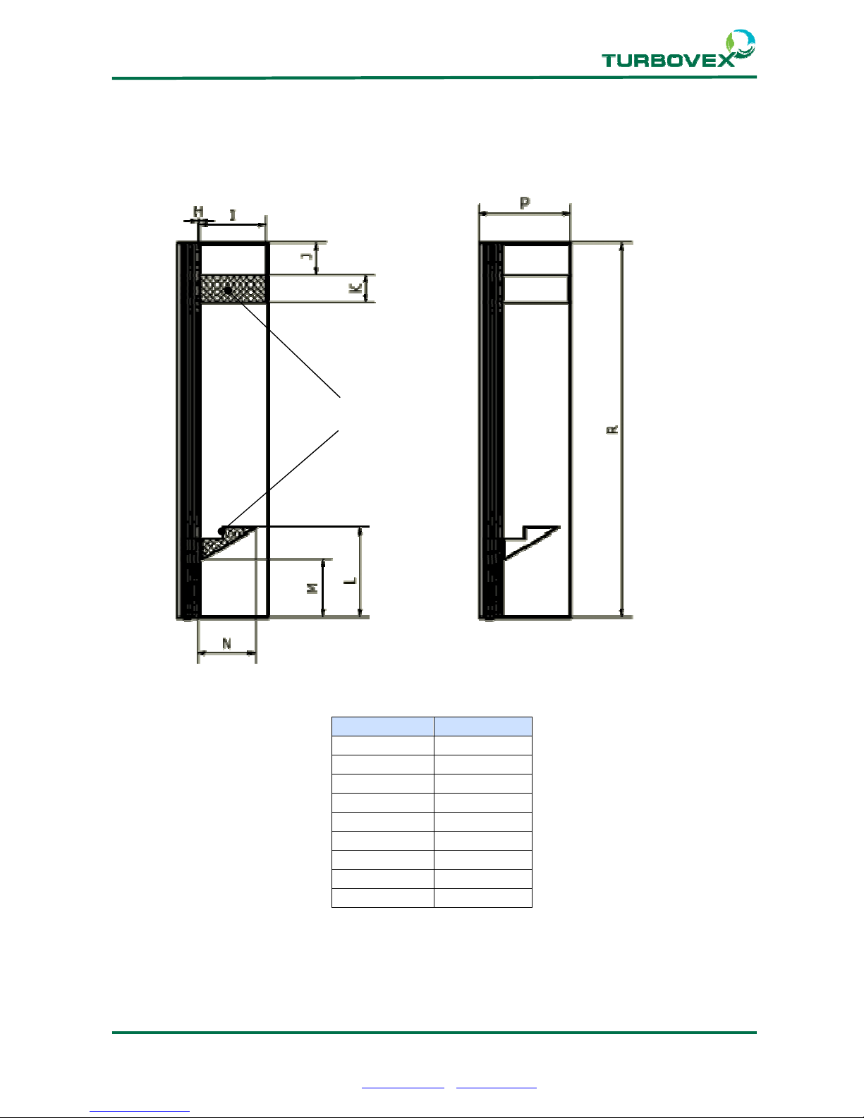
3.2.0 Wall/window installation
Internal reinforcement is built into the sides within the marked areas. Holes can be drilled
in these areas as required for installation.
Dimensions: TX350A
H 10
I 235
J 105
K 90
L 335
M 220
N 205
P 336
R 1400
Safe area
for holes
Page 8
Page 8 of 23
Turbovex A/S
Industrivej 45, DK – 9600 Aars
Tel: +45 96 98 14 62 – Fax: +45 98 96 42 24
e-mail: [email protected] – www.turbovex.dk
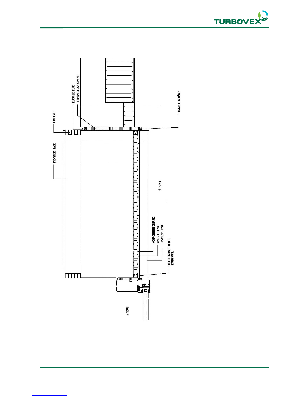
Plane cross-section for window/wall
Page 9
Page 9 of 23
Turbovex A/S
Industrivej 45, DK – 9600 Aars
Tel: +45 96 98 14 62 – Fax: +45 98 96 42 24
e-mail: [email protected] – www.turbovex.dk
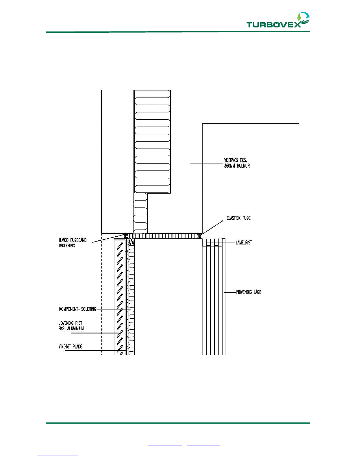
Vertical cross-section, upper part
Page 10
Page 10 of 23
Turbovex A/S
Industrivej 45, DK – 9600 Aars
Tel: +45 96 98 14 62 – Fax: +45 98 96 42 24
e-mail: [email protected] – www.turbovex.dk
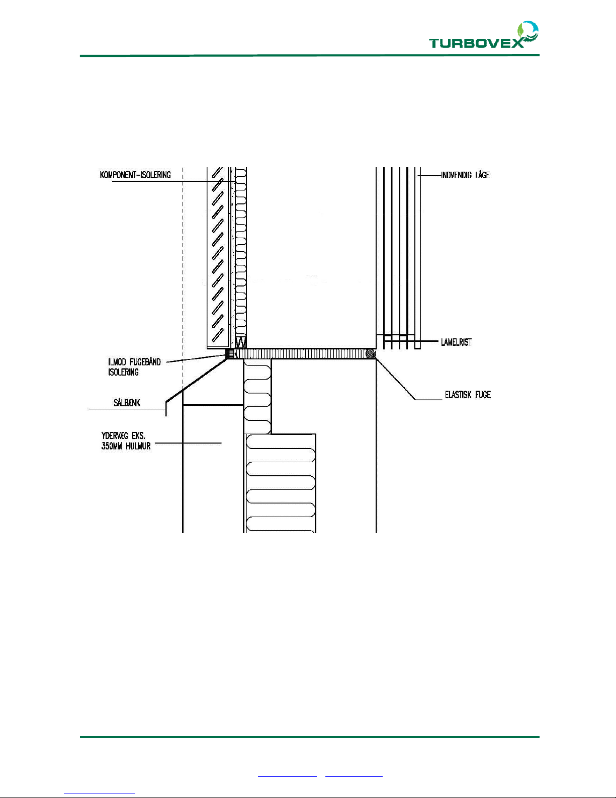
Vertical cross-section, lower part
Page 11
Page 11 of 23
Turbovex A/S
Industrivej 45, DK – 9600 Aars
Tel: +45 96 98 14 62 – Fax: +45 98 96 42 24
e-mail: [email protected] – www.turbovex.dk
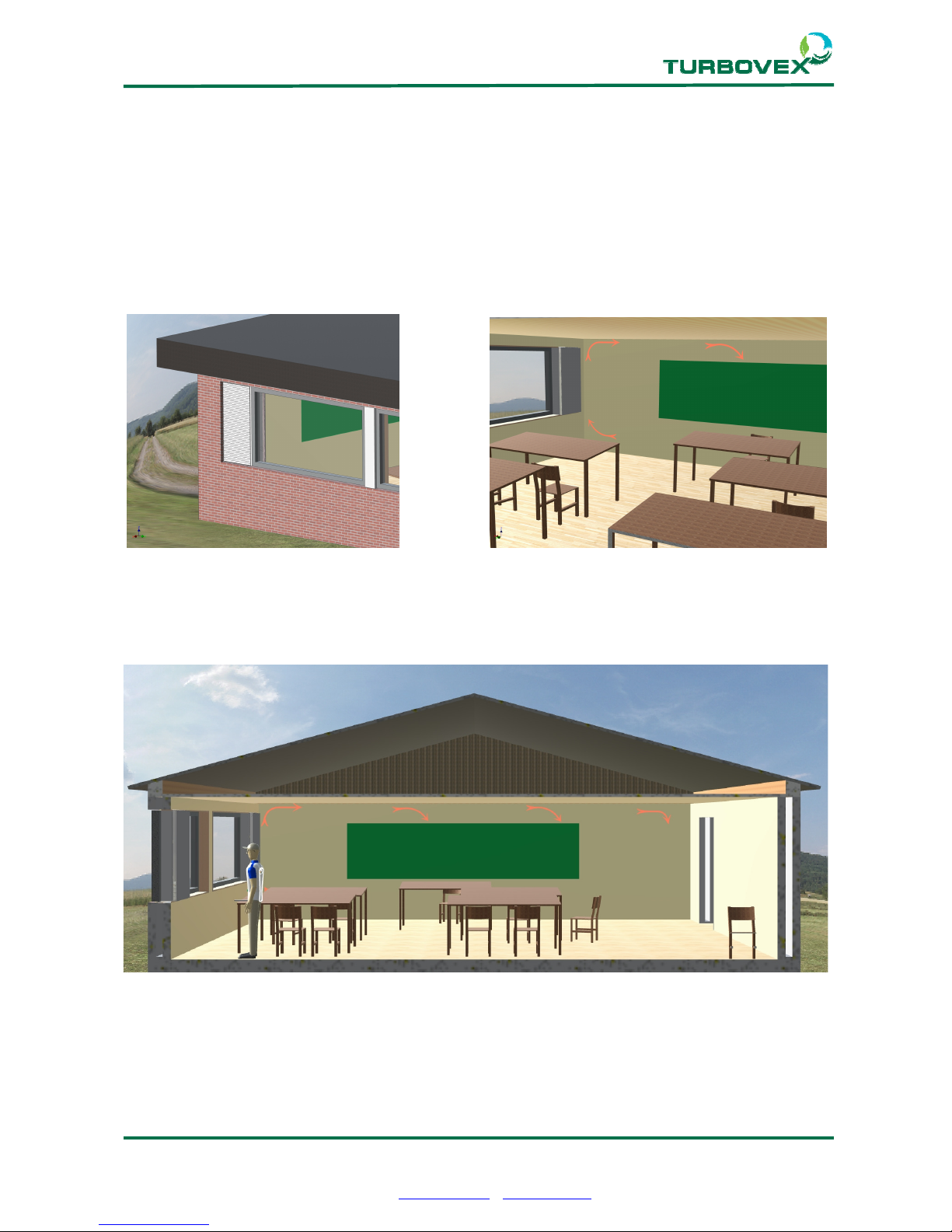
4.0.0 Placing the unit
The unit is usually placed in the wall by a window. This position makes the most of the
coanda effect, which circulates fresh air well into the room. This gives the air longer to mix
with the existing air in the room, avoiding drafts. The location of the supply grille and
extraction provide optimum circulation in the room.
Page 12
Page 12 of 23
Turbovex A/S
Industrivej 45, DK – 9600 Aars
Tel: +45 96 98 14 62 – Fax: +45 98 96 42 24
e-mail: [email protected] – www.turbovex.dk
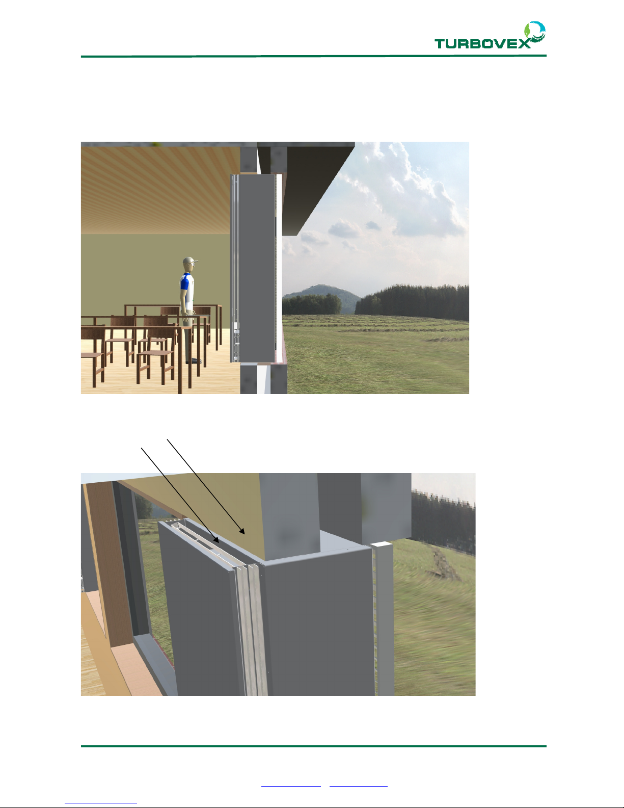
Placing the unit
(cont.)
Place the unit with the edge of the cabinet flush with the inside of the wall in the room.
Ensure free air passage in both directions
These surfaces should be flush
Page 13
Page 13 of 23
Turbovex A/S
Industrivej 45, DK – 9600 Aars
Tel: +45 96 98 14 62 – Fax: +45 98 96 42 24
e-mail: [email protected] – www.turbovex.dk
5.0.0 Service
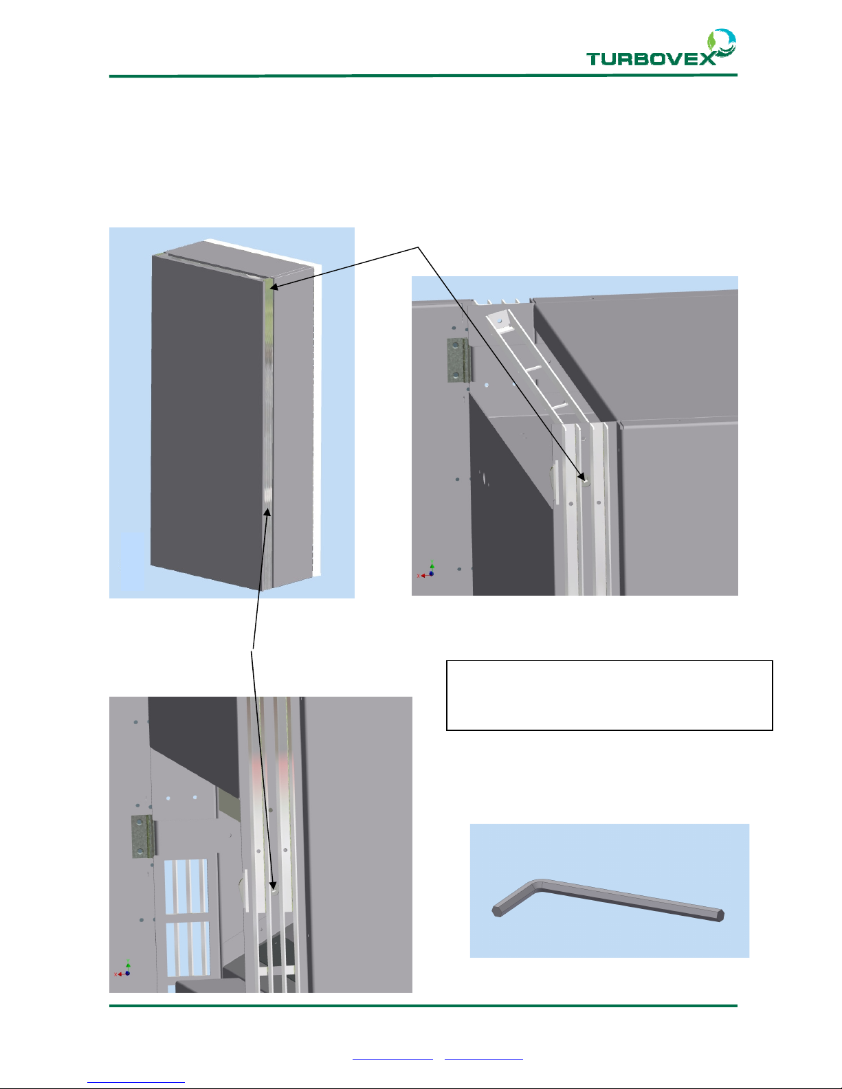
5.1.0 Filter change
We recommend changing the filters and carefully cleaning the exchanger 2- 4 times a
year.
Upper keyhole
Lower keyhole
Use a 6mm Allen key
NOTE!
Disconnect from mains electricity before
opening the front
Page 14
Page 14 of 23
Turbovex A/S
Industrivej 45, DK – 9600 Aars
Tel: +45 96 98 14 62 – Fax: +45 98 96 42 24
e-mail: [email protected] – www.turbovex.dk
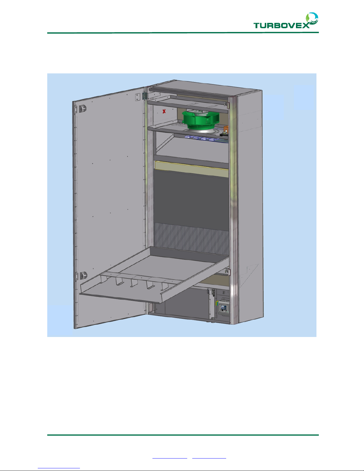
5.2.0 Removing filters and exchanger
Page 15
Page 15 of 23
Turbovex A/S
Industrivej 45, DK – 9600 Aars
Tel: +45 96 98 14 62 – Fax: +45 98 96 42 24
e-mail: [email protected] – www.turbovex.dk
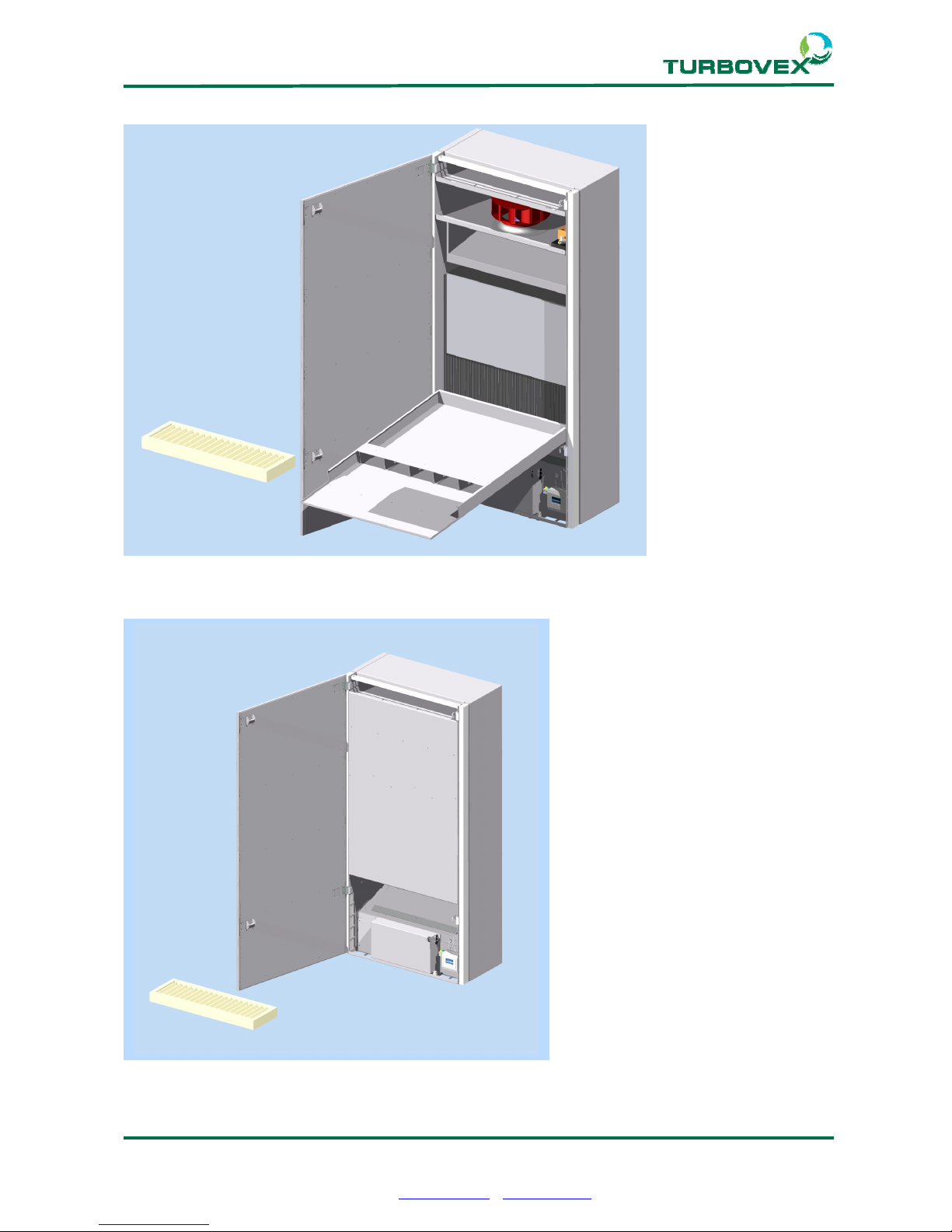
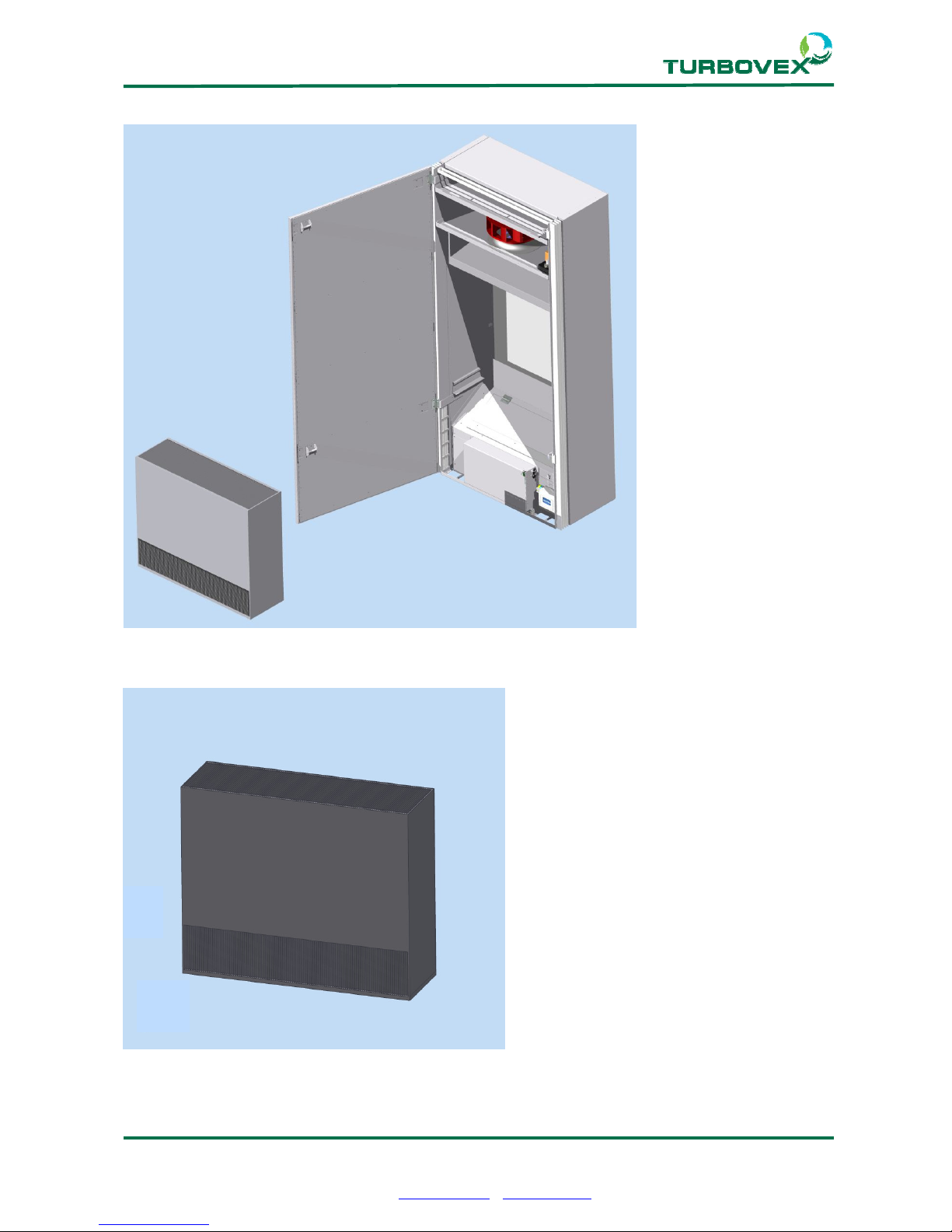
Change upper filter with inner door open.
Change lower filter with inner door closed.
Page 16
Page 16 of 23
Turbovex A/S
Industrivej 45, DK – 9600 Aars
Tel: +45 96 98 14 62 – Fax: +45 98 96 42 24
e-mail: [email protected] – www.turbovex.dk
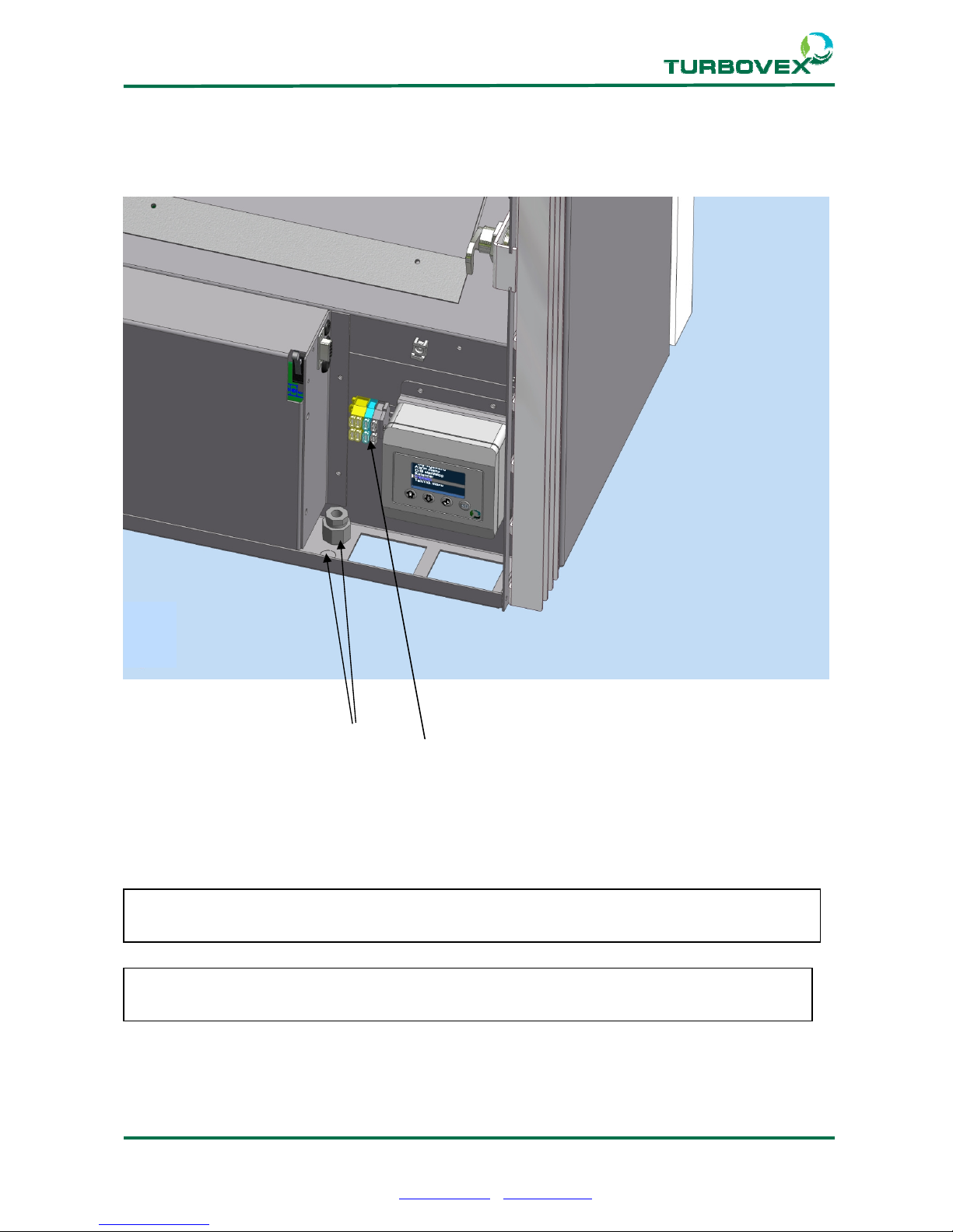
Remove inner door and filters to be able to lift out the heat exchanger.
Clean heat exchanger carefully using a vacuum cleaner with a soft brush head.
Page 17
Page 17 of 23
Turbovex A/S
Industrivej 45, DK – 9600 Aars
Tel: +45 96 98 14 62 – Fax: +45 98 96 42 24
e-mail: [email protected] – www.turbovex.dk
6.0.0 Connecting mains electricity
6.1.0 Connection
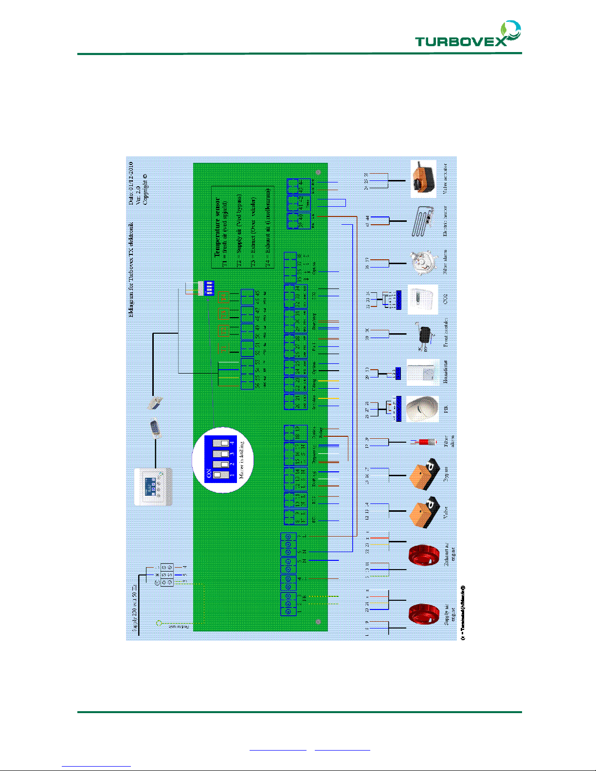
Cable grommet holes
Terminal clamps for connecting mains electricity
Note!
Connection of mains electricity must be performed by an authorised electrician
Note!
A circuit breaker must be mounted prior to the ventilation unit
Page 18
Page 18 of 23
Turbovex A/S
Industrivej 45, DK – 9600 Aars
Tel: +45 96 98 14 62 – Fax: +45 98 96 42 24
e-mail: [email protected] – www.turbovex.dk
6.2.0 Wiring diagram
Connect Turbovex unit according to wiring diagram
Page 19
Page 19 of 23
Turbovex A/S
Industrivej 45, DK – 9600 Aars
Tel: +45 96 98 14 62 – Fax: +45 98 96 42 24
e-mail: [email protected] – www.turbovex.dk
7.0.0 Technical specifications
The airflow indicates the balanced air change in relation to motor voltage stated in m3/h.
The standard unit setting is max. (see table above). If forced operation is required, please
contact the dealer.
Noise level is stated in dB(A) in relation to air change, measured at a distance of 1 metre
from and 1,2 m below the supply air grille. For comparison, a whisper is equivalent to 30
dB(A), ordinary speech 60 dB(A) and urban traffic approx. 90 dB(A).
Temperature efficiency degree at the heat exchanger is stated in % and is the relationship
between the temperature differences achieved and the maximum achievable temperature
difference, i.e. the outdoor temperature minus supply temperature divided by the outdoor
temperature minus room temperature, converted to percent.
TX 350A Unit
Dimensions:
Height 1400 mm
Width
662
mm
Depth (without insulation
and grille)
336
mm
Weight: 47 Kg
Capacity:
Min. 170 m³/h
Max 330 m³/h
Forced 730 m³/h
Noise level:
Min. 26 dB(A)
Max. 35 dB(A)
Forced 55 dB(A)
Filter: M5 Filter class
Energy consumption (unit):
13.8 W
Min. 311 J/m³
28.6 Watt
Max. 315 J/m³
167 Watt
Forced
826 J/m³
Output (motor): 2 x 82 W
Electricity supply 1 ~ 230 / 50 V / Hz
Temperature efficiency: 90,5 %
Electric heater 650 Watt
Page 20
Page 20 of 23
Turbovex A/S
Industrivej 45, DK – 9600 Aars
Tel: +45 96 98 14 62 – Fax: +45 98 96 42 24
e-mail: [email protected] – www.turbovex.dk
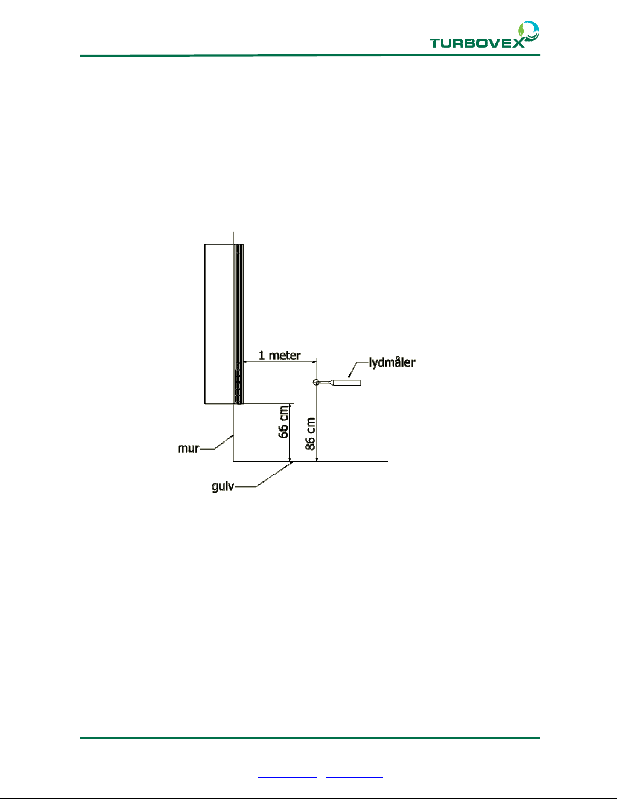
7.1.0 Sound test
Sound test performed in our laboratory on 12-10-11
Principle Sketch
Result:
30 dB ≈ 290m³/h consumption 23,4W (290 J/m³)
35 dB ≈ 345m³/h consumption 30W (313 J/m³)
Page 21
Page 21 of 23
Turbovex A/S
Industrivej 45, DK – 9600 Aars
Tel: +45 96 98 14 62 – Fax: +45 98 96 42 24
e-mail: [email protected] – www.turbovex.dk
8.0.0 Principle of operation
8.1.0 Description
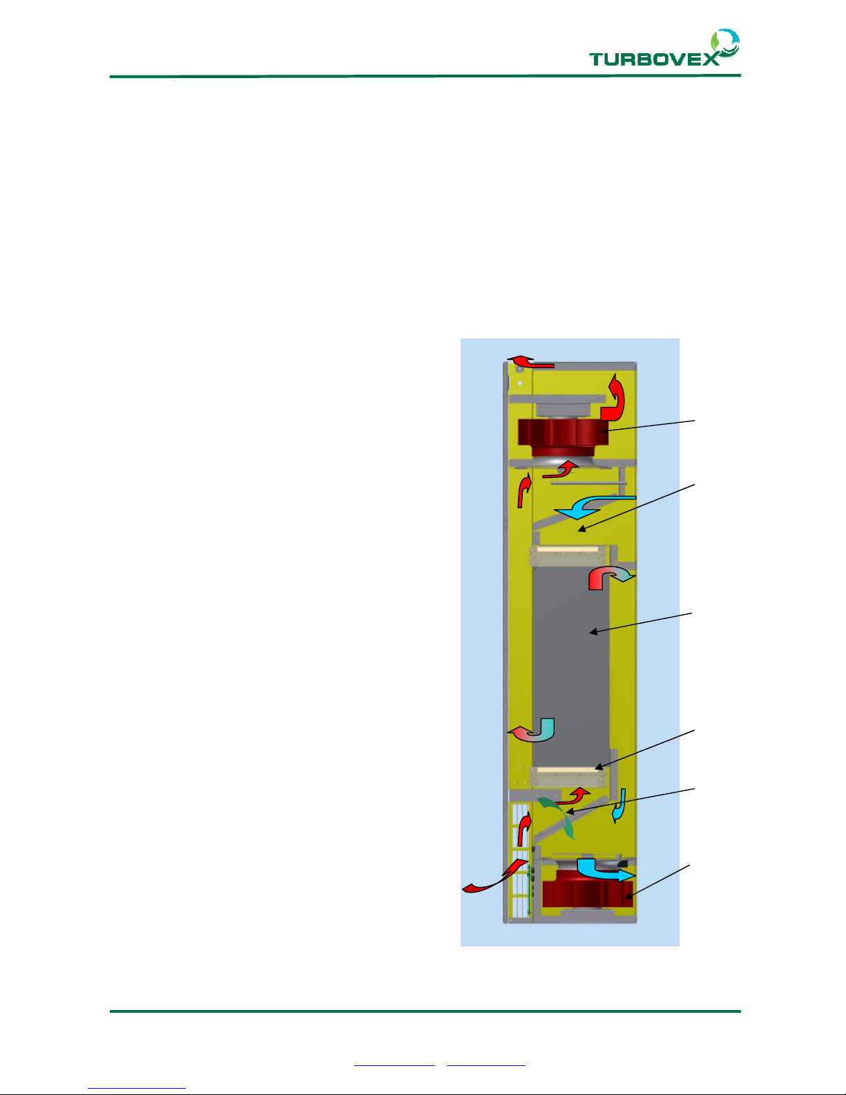
The unit contains a counterflow heat exchanger and two fans, which enable the extraction
of warm air from a room and concurrent supply of cold fresh air from outdoors. Heat
exchange occurs by using the warmth from the extracted air to heat the cold fresh air.
Airflow:
Supply air fan (1) draws in fresh air, passes it
through the filter (3), the heat exchanger (2), up
through the fan blade, out through the louvres
in the top and in to the room.
The extract air fan (4) draws air from the room
through the louvres in the bottom and sides, up
through the filter (5), through the heat
exchanger (2), down through the fan blades,
which blows it out at the bottom of the back.
Bypass:
When the bypass damper (6) opens, the air is
drawn through the unit, bypassing the heat
exchanger and direct into the room.
Regulation:
The temperature desired is set on the control
panel for the supply air.
A sensor registers the actual temperature of the
supply air, and if it is lower than the set value,
the control system will turn down the supply air
volume.
The air will thus be warmer as it passes through
the heat exchanger.
1
Page 22

Page 22 of 23
Turbovex A/S
Industrivej 45, DK – 9600 Aars
Tel: +45 96 98 14 62 – Fax: +45 98 96 42 24
e-mail: [email protected] – www.turbovex.dk
9.0.0 Operation
9.1.0 Regulating air volume
See also the user guide enclosed for the TX electronic controller.
The unit has 2 operating settings. One for daytime, which gives the dimensioned air
volume the unit is set for by the factory, and one night time operation, which runs slower,
to save energy at night.
NB! If air volume is regulated by a CO2 sensor, the unit will adjust its speed according to
conditions in the room.
9.2.0 Regulating temperature
See also the user guide enclosed for the TX electronic controller.
The temperature required is set on the control panel. We recommend that the temperature
should not be set higher than the room temperature. Fresh air temperature should be 2-3
degrees below room temperature to achieve the best circulation in the room.
When the unit is stopped, the last temperature setting is automatically saved, and the unit
will start using that setting.
The unit has a fully-automatic by-pass system, which directs the air past the exchanger
when the temperature permits.
9.3.0 Master/slave
To use this function, a PCB board is required. Contact your dealer.
5 slaves can be connected to one master. This means that one unit can be used to control
5 other units, so that all 6 units run uniformly.
See the user guide for correct master/slave setup.
The unit is programmed as a master as standard.
NOTE!
Units with electrical comfort heaters always have a run-on time of approx.
80 seconds.
Page 23

Page 23 of 23
Turbovex A/S
Industrivej 45, DK – 9600 Aars
Tel: +45 96 98 14 62 – Fax: +45 98 96 42 24
e-mail: [email protected] – www.turbovex.dk
10.0.0 Declaration of compliance
Manufacturer:
Name: Turbovex A/S
Address: Industrivej 45
DK-9600 Aars
Country: Denmark
Tel: +45 96 98 14 62
Dealer:
Name: Turbovex A/S
Address: Industrivej 45
DK-9600 Aars
Country: Denmark
Tel: +45 96 98 14 62
hereby declares that
Product:
Name: TX 350A
Serial no.: 300-000-000
Name: TX 150A
Serial no.: 150-000-000
complies with
Council Directive of 17 May 2006 on harmonisation of member state legislation on electrical materiel intended for use within certain
voltage ranges (2006/42/EC)
has been manufactured in accordance with the following national standards. which implement a harmonised standard:
DS/EN 12100-1/A1:2009
Safety of Machines - Basic concepts, general principles for design - Part 1:
Basic terminology and methodology (ISO 12100-1:2003)
DS/EN 12100-2/A1:2009
Safety of Machines - Basic concepts, general principles for design - Part 2: Technical principles (ISO 12100-2:2003)
DS/EN 60269-1/A1:2009
Low voltage fuses – Part 1: General requirements (IEC 60269-1-1998) supplement A1:2005 to
DS/EN ISO 13857:2008
Safety of machinery - Safety distances to prevent hazard zones being reached by upper and lower limbs
DS/EN 61000-6-1:2007
Electromagnetic compatibility (EMC) Part 6-1: Generic standards, Immunity for residential, commercial and light-industrial environments
DS/EN 61000-6-3:2007
Electromagnetic compatibility (EMC) Part 6-3: Generic standards, Emissions standards for residential, commercial and light-industrial
environments
DS/EN 61000-6-4:2007
Electromagnetic compatibility (EMC) Part 6-4: Generic standards, Emission standard for industrial environments
Aars
Date: Production Technologist: Arne Christensen
 Loading...