

Turbovex TX 250A, TX 1000A, TX 500A, TX 750A Installation, Operation And Maintanance Manual

Page 1 of 24
Turbovex A/S
Industrivej 45, DK – 9600 Aars
Telefon: +45 96 98 14 62 – Fax: +45 98 96 42 24
e-mail: info@turbovex.dk
– www.turbovex.dk
Installation, Operation and
Maintenance Manual
TX 250A TX 500A TX 750A TX 1000A
Rev. 2012.11.06

Page 2 of 24
Turbovex A/S
Industrivej 45, DK – 9600 Aars
Telefon: +45 96 98 14 62 – Fax: +45 98 96 42 24
e-mail: info@turbovex.dk
– www.turbovex.dk
1.0.0 Table of contents
1.0.0 TABLE OF CONTENTS ........................................................................................................................................2
2.0.0 ILLUSTRATIONS ..................................................................................................................................................2
3.0.0 GENERAL INFORMATION.................................................................................................................................3
3.1.0 FOREWORD........................................................................................................................................................3
3.2.0 FIELDS OF APPLICATION................................................................................................................................3
3.3.0 MISUSE................................................................................................................................................................3
3.4.0 CONTENTS OF DELIVERY...............................................................................................................................3
3.4.0 OPERATING PRINCIPLE...................................................................................................................................4
3.5.0 MAIN COMPONENTS:.......................................................................................................................................5
4.0.0 INSTALLATION.....................................................................................................................................................6
4.1.0 SCALE ILLUSTRATION.....................................................................................................................................6
4.2.0 LOCATION..........................................................................................................................................................7
4.2.1 MINIMUM DISTANCE.......................................................................................................................................9
4.2.2 WALL- OR CEILING-MOUNTED UNIT........................................................................................................... 9
4.3.0 INSTALLATION OF UNIT................................................................................................................................11
4.3.1 INSTALLATION WITH 2 DUCTS....................................................................................................................11
5.0.0 CONNECTION......................................................................................................................................................16
5.1.0 WATER CONNECTION....................................................................................................................................16
5.1.1 FROST PROTECTION OF WATER HEATING COIL .....................................................................................16
5.2.0 POWER CONNECTION....................................................................................................................................18
5.3.0 POWER CONNECTION FOR ACCESSORIES................................................................................................ 19
6.0.0 TECHNICAL SPECIFICATIONS......................................................................................................................20
6.1.0 VENTILATION SYSTEM................................................................................................................................. 20
7.0.0 OPERATION.........................................................................................................................................................21
7.1.0 REGULATION OF AIRFLOW.......................................................................................................................... 21
7.2.0 HEAT REGULATION........................................................................................................................................21
7.3.0
MASTER / SLAVE.............................................................................................................................................21
8.0.0 SERVICE ...............................................................................................................................................................22
8.1.0 CHANGE OF FILTER........................................................................................................................................ 22
8.2.0 CLEANING OF EXCHANGER.........................................................................................................................23
9.0.0 DECLARATION OF CONFORMITY................................................................................................................24
2.0.0 Illustrations
FIGURE 1 CONTENTS OF DELIVERY.............................................................................................................................3
FIGURE 2 MAIN COMPONENTS ......................................................................................................................................5
FIGURE 3 SCALE ILLUSTRATION...................................................................................................................................6
FIGURE 4 LOCATION, CONVENTIONAL....................................................................................................................... 7
FIGURE 5 LOCATION IN A FALSE CEILING..................................................................................................................7
FIGURE 6 MINIMUM DISTANCE.....................................................................................................................................9
FIGURE 7 WALL-MOUNTED WITH WALL DUCTS………..........................................................................10
FIGURE 8 CEILING-MOUNTED WITH CEILING DUCTS…........................................................................................ 10
FIGURE 9 LOCATION OF DUCTS...................................................................................................................................10
FIGURE 10 MEASUREMENTS FOR MOUNTING THE SUSPENSION BRACKET OF A TX COMFORT UNIT...... 11
FIGURE 11 WATER CONNECTION................................................................................................................................ 16
F
IGURE 12 CIRCUIT DIAGRAM .....................................................................................................................................18
F
IGURE 13 CIRCUIT DIAGRAM FOR ACCESSORIES.................................................................................................18

Page 3 of 24
Turbovex A/S
Industrivej 45, DK – 9600 Aars
Telefon: +45 96 98 14 62 – Fax: +45 98 96 42 24
e-mail: info@turbovex.dk
– www.turbovex.dk
3.0.0 General information
3.1.0 Introduction
This user manual contains technical information about installation, operation and
maintenance of the unit.
3.2.0 Fields of application
TX Comfort is designed for comfort ventilation in institutions, offices, dining spaces,
conference rooms and indoor spaces occupied by people.
3.3.0 Misuse
TX Comfort is designed for the living spaces described above in section 3.2.0. The system
is not designed for the purpose of local exhaust ventilation.
3.4.0 Contents of delivery
The TX Comfort unit is delivered with the following main components:
1. Turbovex TX Comfort unit
2. Suspension bracket
3. TX electronic controller
Figure 1 Contents of delivery
1.
2.
3.

Page 4 of 24
Turbovex A/S
Industrivej 45, DK – 9600 Aars
Telefon: +45 96 98 14 62 – Fax: +45 98 96 42 24
e-mail: info@turbovex.dk
– www.turbovex.dk
3.4.0 Operating principle
Turbovex TX Comfort is a decentralized ventilation system with built-in heat recovery for
ventilation of comfort rooms in particular in indoor living spaces.
TX Comfort operates with an aluminium counter flow heat exchanger (5) to ensure
maximum heat recovery. The unit utilizes warm indoor air to heat up inflowing fresh
outdoor air. The counter flow heat exchanger’s sole function is for heat retention.
Airflow:
The air supply ventilator (6) (Figure 2) creates inflow of fresh outdoor air through the filter
(10), leading the inflow through the heat exchanger (5), and further through the air supply
grate (4) and out into the room.
At the same time the air exhaust ventilator (7) creates outflow of indoor air leading it
through the exhaust pipe (2) and further out to the open air outside.
The desired temperature of the air supply is regulated on the control panel. A sensor
records the actual temperature of the flowing air supply. If the temperature is lower than
the setpoint, the control system reduces the flow of the air supply warming it as it flows
through the heat exchanger.

Page 5 of 24
Turbovex A/S
Industrivej 45, DK – 9600 Aars
Telefon: +45 96 98 14 62 – Fax: +45 98 96 42 24
e-mail: info@turbovex.dk
– www.turbovex.dk
3.5.0 Main components:
Figure 2 Main components
Page 6 of 24
Turbovex A/S
Industrivej 45, DK – 9600 Aars
Telefon: +45 96 98 14 62 – Fax: +45 98 96 42 24
e-mail: info@turbovex.dk
– www.turbovex.dk
4.0.0 Installation
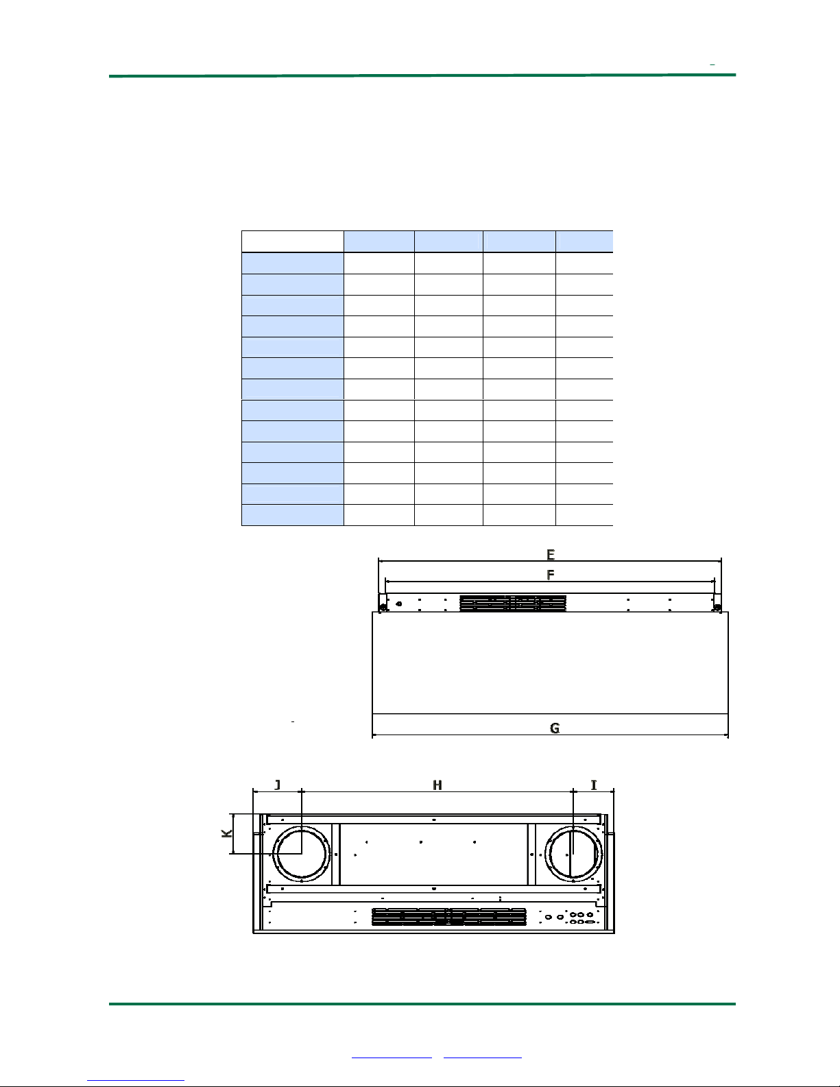
4.1.0 Scale illustration
Figure 3 Dimension Drawing
Dimension [mm] TX 250A TX 500A TX 750A TX 1000
A
A 595.00 828.00 895.00 1050.00
B 403.00 493.00 565.00 665.00
C 500.00 710.00 766.00 917.00
D 313.00 382.00 442.00 542.00
E 1155.50 1505.50 1766.50 2066.50
F 1141.00 1491.00 1750.00 2050.00
G 1200.00 1550.00 1800.00 2100.00
H 906.00 1156.00 1355.00 1630.00
I 134.50 189.00 210.00 235.00
J 159.50 205.00 235.00 235.00
K 136.60 186.60 202.50 252.50
L 280,00 350,00 390,00 465,00
M 185,00 245,00 280,00 310,00

Page 7 of 24
Turbovex A/S
Industrivej 45, DK – 9600 Aars
Telefon: +45 96 98 14 62 – Fax: +45 98 96 42 24
e-mail: info@turbovex.dk
– www.turbovex.dk
4.2.0 Location
The unit is generally placed on a wall directly under the ceiling. This location best exploits
the coanda effect as it leads the air further into the room along the surface of the ceiling. In
this way inflowing air can mix with the room’s existing air for a longer period of time and
thereby prevent draught. This location, as the point for supply and exhaust airflow,
provides optimal circulation within a room.
Figure 4 Location, conventional
The TX Comfort series also has the possibility of locating the unit in false ceilings. In this
way, the unit is less visible.
Figure 5 Location in a false ceiling

Page 8 of 24
Turbovex A/S
Industrivej 45, DK – 9600 Aars
Telefon: +45 96 98 14 62 – Fax: +45 98 96 42 24
e-mail: info@turbovex.dk
– www.turbovex.dk
The TX Comfort series offer the possibility of installing ducts through the wall or the roof.
Fresh air can also flow in through a wall duct while exhaust air flows out through the roof.
This results in optimal conditions in comparison to a set up with close proximity between
the air supply and the air exhaust.
 Loading...