

Turbovex TX 350A, TX 75A Installation, Operation And Maintenance Manual

Page 1 of 23
Turbovex A/S
Industrivej 45, DK – 9600 Aars
Tel: +45 96 98 14 62 – Fax: +45 98 96 42 24
e-mail: info@turbovex.dk – www.turbovex.dk
Installation, operation and
maintenance guide
for window models
Rev. 2014.06.25

Page 2 of 23
Turbovex A/S
Industrivej 45, DK – 9600 Aars
Tel: +45 96 98 14 62 – Fax: +45 98 96 42 24
e-mail: info@turbovex.dk – www.turbovex.dk
Table of content
2.0.0 GENERAL INFORMATION...................................................................................................................... 3
2.1.0 P
REFACE
................................................................................................................................................ 3
2.2.0 A
REAS OF USE
........................................................................................................................................ 3
2.3.0 I
NCORRECT USE
...................................................................................................................................... 3
2.4.0 S
COPE OF DELIVERY
............................................................................................................................... 3
2.5.0 M
AIN COMPONENTS
: ............................................................................................................................... 4
F
IGURE 2: MAIN COMPONENTS
......................................................................................................................... 4
F
IGURE 3 MAIN COMPONENTS
.......................................................................................................................... 5
3.0.0 INSTALLATION OF UNIT ........................................................................................................................ 6
3.1.0. E
XTERNAL DIMENSIONS
.......................................................................................................................... 6
3.2.0 W
ALL/WINDOW INSTALLATION
.................................................................................................................. 7
4.0.0 PLACING THE UNIT .............................................................................................................................. 11
PLACING THE UNIT (CONT.) ........................................................................................................................ 12
5.0.0 SERVICE ................................................................................................................................................ 13
5.1.0 F
ILTER CHANGE
.................................................................................................................................... 13
5.2.0 R
EMOVING FILTERS AND EXCHANGER
..................................................................................................... 14
6.0.0 CONNECTING MAINS ELECTRICITY .................................................................................................. 17
6.1.0 C
ONNECTION
........................................................................................................................................ 17
6.2.0 W
IRING DIAGRAM
.................................................................................................................................. 18
7.0.0 TECHNICAL SPECIFICATIONS............................................................................................................ 19
7.1.0 S
OUND TEST
......................................................................................................................................... 20
8.0.0 PRINCIPLE OF OPERATION ................................................................................................................ 21
8.1.0 D
ESCRIPTION
....................................................................................................................................... 21
9.0.0 OPERATION .......................................................................................................................................... 22
9.1.0 R
EGULATING AIR VOLUME
...................................................................................................................... 22
9.2.0 R
EGULATING WARMTH
........................................................................................................................... 22
9.3.0 M
ASTER/SLAVE
..................................................................................................................................... 22
10.0.0 DECLARATION OF COMPLIANCE .................................................................................................... 23
Page 3 of 23
Turbovex A/S
Industrivej 45, DK – 9600 Aars
Tel: +45 96 98 14 62 – Fax: +45 98 96 42 24
e-mail: info@turbovex.dk – www.turbovex.dk
2.0.0 General information
Turbovex TX 350A and TX 75A are decentralized ventilation units with integrated heat
recovery.
2.1.0 Preface
This installation and operation guide contains technical information and details of
installation and maintenance of the unit.
2.2.0 Areas of use
Window models are designed for comfort ventilation for institutions, canteens, offices and
conference rooms etc.
2.3.0 Incorrect use
The window models are not designed for local exhaust ventilation, and are therefore not
suitable for this purpose.
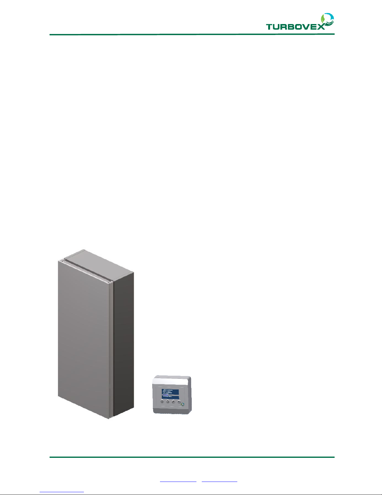
2.4.0 Scope of delivery
TX window models are supplied with the following main components:
1. Turbovex TX window model
2. TX electronic controller
Figure 1 Deliverables
Page 4 of 23
Turbovex A/S
Industrivej 45, DK – 9600 Aars
Tel: +45 96 98 14 62 – Fax: +45 98 96 42 24
e-mail: info@turbovex.dk – www.turbovex.dk
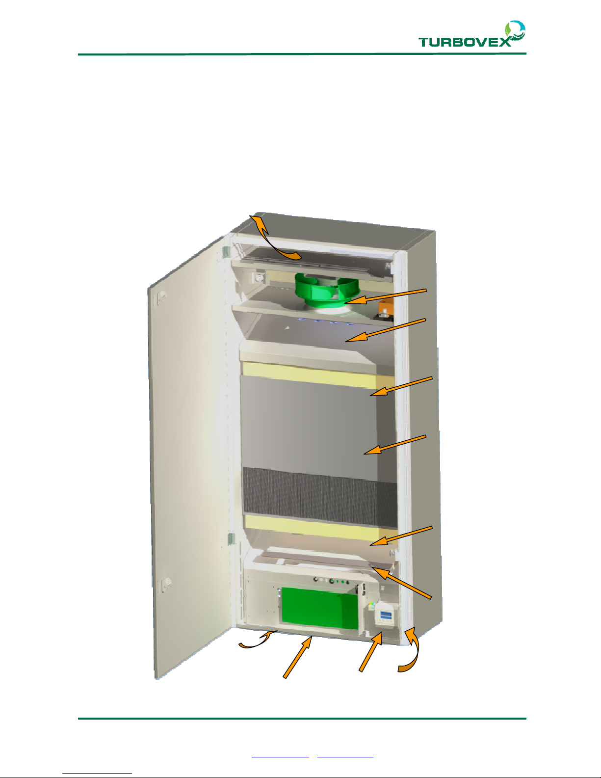
2.5.0 Main components:
Figure 2: Main components
1. Intake Air
2. Exhaust Air
3. Extract Air
4. Supply Air
5. Counterflow heat exchanger
6. Supply Air Fan
7. Extract Air Fan
8. Bypass Damper
9. Electrical heater
10. Filter
11. Main PCB
12. TX Controller
11
3
4
5
6
9
10
8
10
12
3
Page 5 of 23
Turbovex A/S
Industrivej 45, DK – 9600 Aars
Tel: +45 96 98 14 62 – Fax: +45 98 96 42 24
e-mail: info@turbovex.dk – www.turbovex.dk
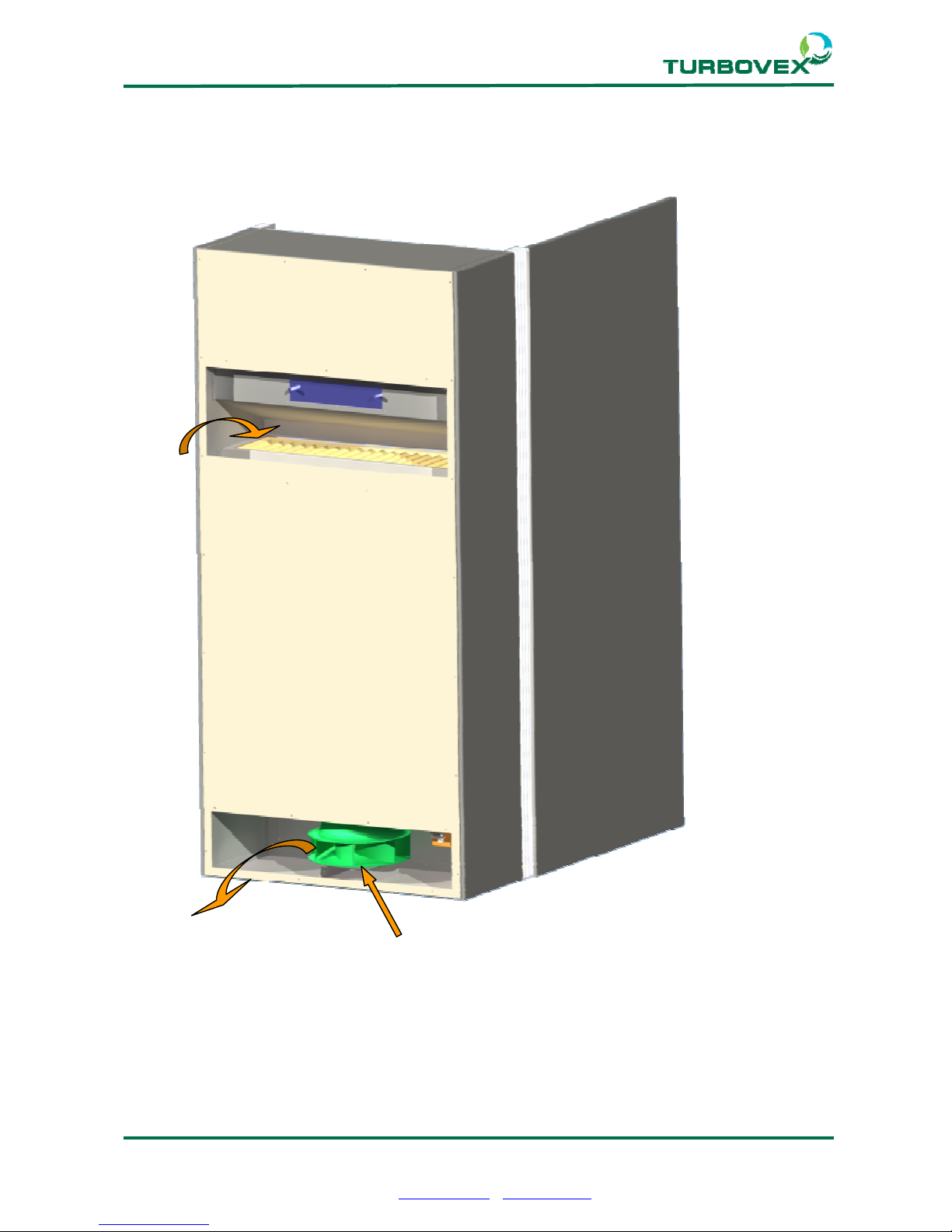
Figure 3 Main components
1
2
7
Page 6 of 23
Turbovex A/S
Industrivej 45, DK – 9600 Aars
Tel: +45 96 98 14 62 – Fax: +45 98 96 42 24
e-mail: info@turbovex.dk – www.turbovex.dk
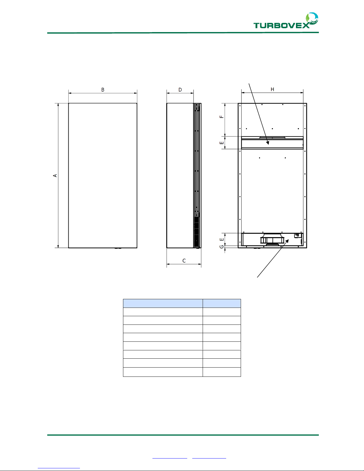
3.0.0 Installation of unit
3.1.0. External dimensions
Intake zone
Minimum required distance to walls, floor and ceiling is 70 mm.
Dimensions (mm) TX350A
A (Height) 1400
B (Width) 662
C (Depth) 334
D (Mounting Dimension) 260
E (Hole Height) 122
F (Hole Distance Upper) 322
G (Hole Distance Lower) 20
H (Hole Width) 597
Exhaust Zone
Page 7 of 23
Turbovex A/S
Industrivej 45, DK – 9600 Aars
Tel: +45 96 98 14 62 – Fax: +45 98 96 42 24
e-mail: info@turbovex.dk – www.turbovex.dk
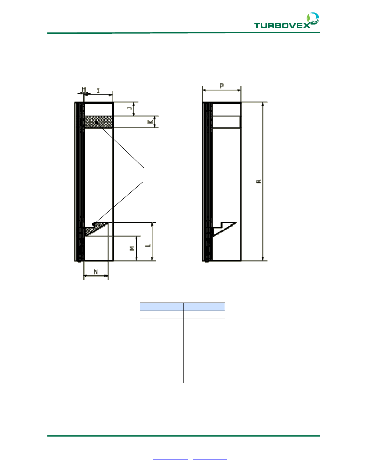
3.2.0 Wall/window installation
Internal reinforcement is built into the sides within the marked areas. Holes can be drilled
in these areas as required for installation.
Dimensions: TX350A
H 10
I 235
J 105
K 90
L 335
M 220
N 205
P 336
R 1400
Safe area
for holes
 Loading...