

Turbovex TX 3100A User Manual & Installation Manual
Page 1 of 20
Turbovex A/S
Industrivej 45, DK – 9600 Aars
Telefon: +45 96 98 14 62 – Fax: +45 98 96 42 24
e-mail: info@turbovex.dk – www.turbovex.dk
User manual –
Installation guide
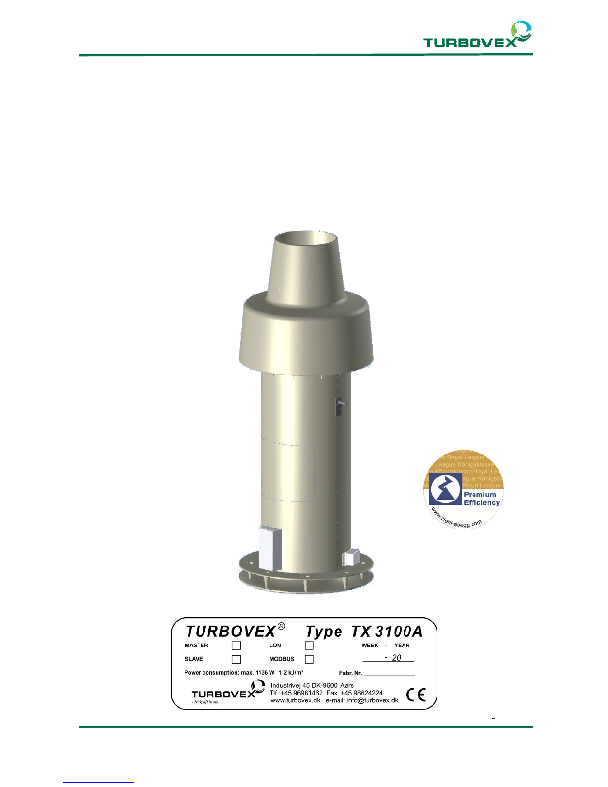
TX 3100A
Rev. 2018.04.12

Page 2 of 20
Turbovex A/S
Industrivej 45, DK – 9600 Aars
Telefon: +45 96 98 14 62 – Fax: +45 98 96 42 24
e-mail: info@turbovex.dk – www.turbovex.dk
1.0.0 TABLE OF CONTENT
Indhold
1.0.0 TABLE OF CONTENT........................................................................................................................................... 2
3.0.0 GENEREL INFORMATION ................................................................................................................................. 3
3.1.0 FOREWORD ............................................................................................................................................................ 3
3.2.0 FIELD OF APPLICATION ........................................................................................................................................... 3
3.3.0 LIST OF PARTS ........................................................................................................................................................ 3
3.4.0 FUNCTION OF THE UNIT .......................................................................................................................................... 4
4.0.0 INSTALLATION ..................................................................................................................................................... 5
4.1.0 DIMENSIONS .......................................................................................................................................................... 5
4.2.0 PLACEMENT ........................................................................................................................................................... 6
4.3. TEMPLATE ............................................................................................................................................................... 6
4.4.0 INSTALLING THE UNIT (STANDARD MOUNTING BRACKETS) .................................................................................... 7
4.5.0 INSTALLING THE UNIT USING SPECIAL BRACKETS................................................................................................... 8
4.6.0 INSTALLING BOTTOM EXTENSION ......................................................................................................................... 11
4.7.0 INSTALLING TOP EXTENSION ................................................................................................................................ 12
5.0.0 TECHNICAL SPECIFICATIONS ...................................................................................................................... 13
5.1.0 UNIT .................................................................................................................................................................... 13
6.0.0 ELECTRICAL INSTALLATION ....................................................................................................................... 14
7.0.0 SERVICE ............................................................................................................................................................... 18
7.1.0 SERVICE REPORT .................................................................................................................................................. 18
7.2.0 FILTER CHANGE ................................................................................................................................................... 19
8.0.0 DECLARATION OF CONFORMITY ................................................................................................................ 20
Page 3 of 20
Turbovex A/S
Industrivej 45, DK – 9600 Aars
Telefon: +45 96 98 14 62 – Fax: +45 98 96 42 24
e-mail: info@turbovex.dk – www.turbovex.dk
3.0.0 Generel information
3.1.0 Foreword
This user´s manual contains technical information regarding the installation and
maintenance of the ventilation unit Turbovex TX 3100A.
3.2.0 Field of application
Turbovex TX 3100A is designed for comfort ventilation in industrial buildings, garages and
sports halls.
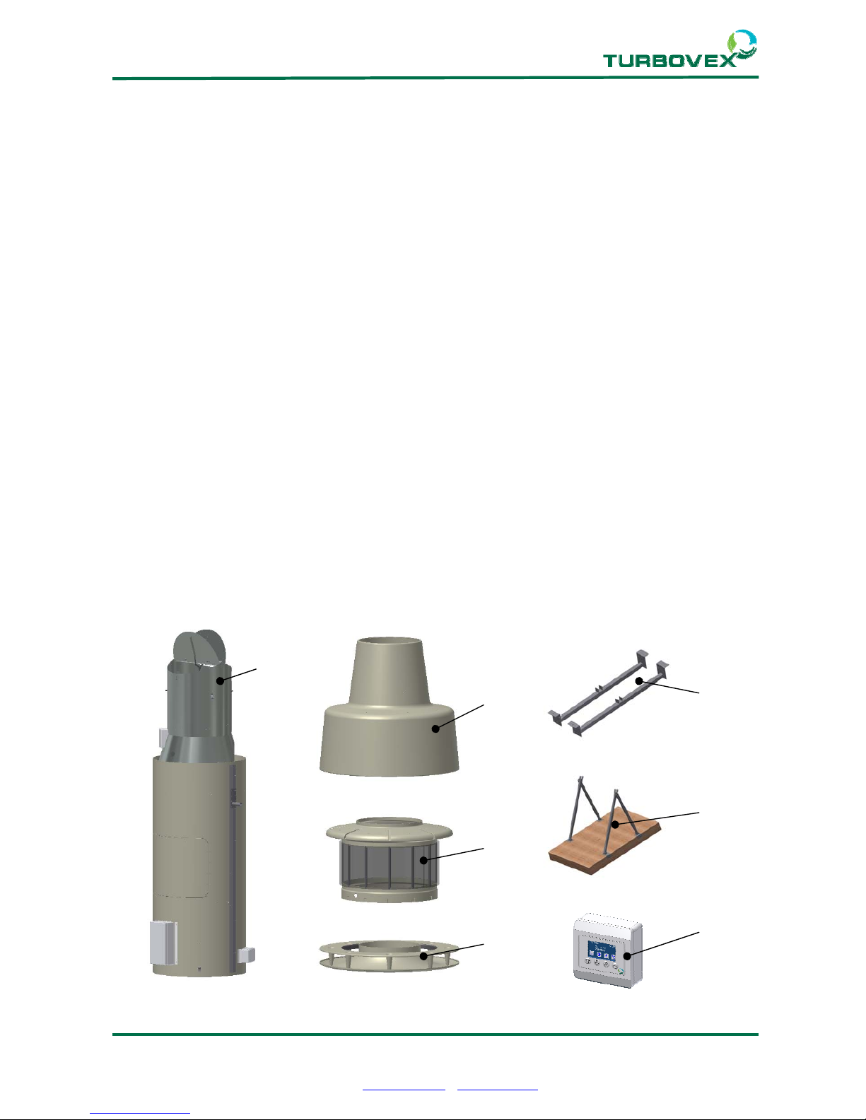
3.3.0 List of parts
Turbovex TX 3100A is delivered with the following key components.
1. TX 3100A unit
2. Top cone
3. Filter holder
4. Inlet ring
5. Standard mounting brackets
6. Special mounting brackets (optional)
7. TX electronic control
8. Silicone rubber + various screws and bolts. Wire and wire tensioners.
1.
3.
4.
5.
2.
7.
6.
Page 4 of 20
Turbovex A/S
Industrivej 45, DK – 9600 Aars
Telefon: +45 96 98 14 62 – Fax: +45 98 96 42 24
e-mail: info@turbovex.dk – www.turbovex.dk
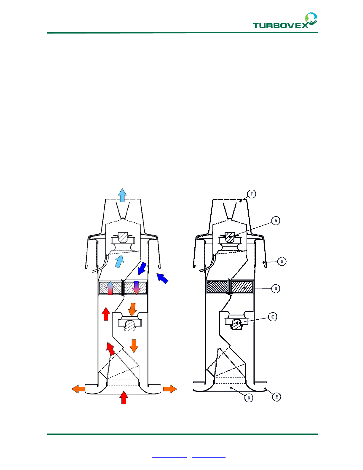
3.4.0 Function of the unit
The principle of the heat recovery in the Turbovex TX3100A is based on the rotating heat
exchanger (B). The exhaust fan (A) extracts the warm room air from the funnel (D) though
half of the heat exchanger (B), and send it through the exhaust cap (F).
Simultaneously the inlet fan will (C) sucks air from the inlet cap (G) and send it through the
other half of the heat exchanger.
The heated fresh air is sent to (E), and diffused in the room.
One half of the rotating heat exchanger will heat up in the warm flow of the exhaust air.
When the heated material in the heat exchanger is in the cool flow of the inlet air, it will
deliver heat from the material to the fresh air.
The process is regenerative as the heat exchanger rotates at low rpm.
The heat exchanger is equipped with a cleaning sector creating a low pressure to
eliminate the possibility of undesirable leaks.
Page 5 of 20
Turbovex A/S
Industrivej 45, DK – 9600 Aars
Telefon: +45 96 98 14 62 – Fax: +45 98 96 42 24
e-mail: info@turbovex.dk – www.turbovex.dk
4.0.0 Installation
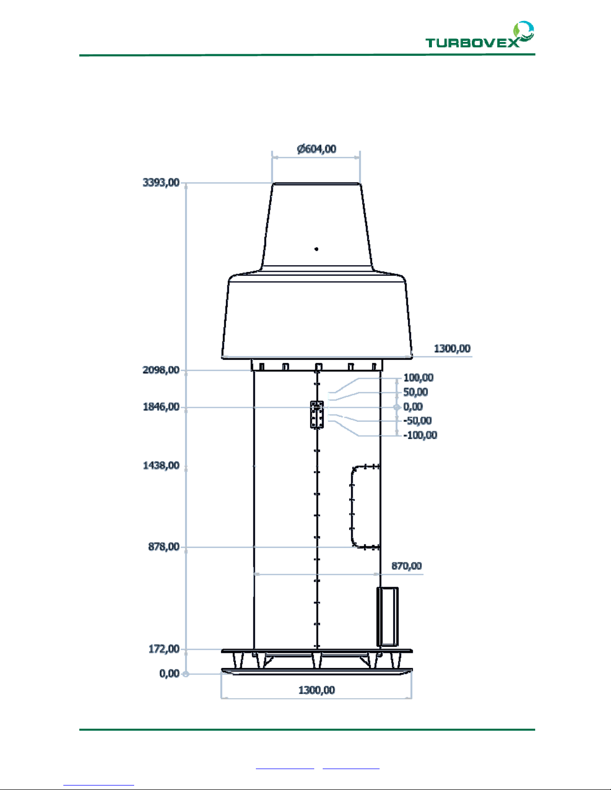
4.1.0 Dimensions
Adjust for
brackets
Page 6 of 20
Turbovex A/S
Industrivej 45, DK – 9600 Aars
Telefon: +45 96 98 14 62 – Fax: +45 98 96 42 24
e-mail: info@turbovex.dk – www.turbovex.dk
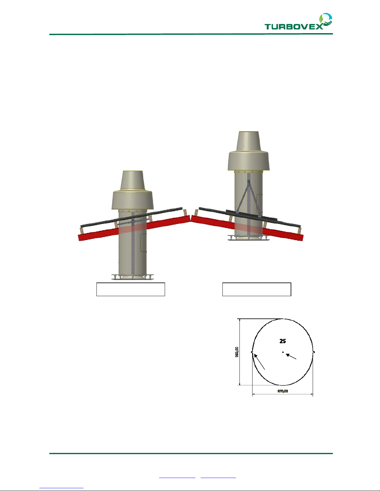
4.2.0 Placement
Turbovex TX 3100A is intended for installation through the roof. The unit can be placed in
roofs with inclines ranging from 0 to 45 degrees. Turbovex TX3100A is available with two
types of mounting brackets.
The standard mounting bracket places the inspection hatch inside the building.
The special mounting bracket is intended for use if you want the hatch placed outside the
building.
4.3. Template
It is a good idea to create a template according to the
incline of the roof. Remember to mark 2 notches and
a center hole. The notches are for placing the unit
horizontally.
a 0 = Ø870 mm
a 5 = 870 x 880 mm
a 10 = 870 x 890 mm
a 15 = 870 x 900 mm
a 20 = 870 x 930 mm
a 25 = 870 x 970 mm
a 30 = 870 x 1010 mm
a 35 = 870 x 1070 mm
a 40 = 870 x 1140 mm
a 45 = 870 x 1240 mm
Standard bracket Special bracket
 Loading...