

Turbosound TXP-151 Datasheet

adjustable gain control, power LED, and
signal and limit LEDs. Balanced 3-pin XLRs
provide input and link out connections from
mixing consoles and to additional powered
TXP enclosures. A two-stage high-pass filter
is user-selectable for stand alone use, or for
correct integration when used with a
subwoofer. Mains power is supplied via an
IEC mains connector with integrated
fuseholder.
The trapezoidal cabinet is constructed from
15mm (5/8”) birch plywood, and the
symmetrical 45° angled sides enable its use
as a compact wedge monitor. A dual angle
pole mount socket is fitted for FOH use with
optional 35mm poles and loudspeaker
stands. Two recessed flush handles are
provided for easy lifting and carrying and
four rubber feet are fitted to the bottom of
the cabinet. A powder-coated perforated
steel mesh grille protects the drive units
from damage.
Rigging points are provided on the top and
rear of the cabinet to enable the TXP-151 to
be suspended in permanent installations.
TXP SERIES ENGINEERING INFORMATION
datasheet
TXP-151
FEATURES
Compact enclosure
Digitally self-powered
Trapezoidal shape
Symmetrical wedge angle
Integral rigging points
Dual angle pole mount
Passive crossover
HF protection system
APPLICATIONS
Live sound
Mobile DJ
Wedge monitoring
Corporate rental
The TXP-151 is a compact trapezoidal self-powered
two-way loudspeaker enclosure designed for use in
a wide variety of live sound, corporate rental and
mobile DJ applications that require professional
sound quality in an easily transportable format.
It consists of a 15” reflex-loaded low
frequency driver and a 1” high frequency
compression driver on a 70°H x 40°V
dispersion HF horn in an optimally tuned
trapezoidal enclosure, together with an
integrated Class D amplifier module.
The Class D amplifier delivers abundant
power to the drive units, separating the
frequency bands via a passive crossover
network, with optimum headroom being
governed by the built-in fast acting limiter
circuits.
The crossover incorporates a two-stage
thermal overload protection system which
prevents damage to the high frequency
driver, reacting instantly to large transient
peaks while still allowing wide dynamic
range to be maintained.
All operating controls and indicators are
provided on the rear panel, including

datasheet
TXP-151
TXP SERIES ENGINEERING INFORMATION
page 2
DIMENSIONS (HxWxD)
NET WEIGHT
COMPONENTS
FREQUENCY RESPONSE
1
NOMINAL DISPERSION
2
MAXIMUM SPL
CONSTRUCTION
GRILLE
CONNECTORS
CONTROLS & INDICATORS
AMPLIFIER
RIGGING HARDWARE
SPARES AND
ACCESSORIES
652mm x 472mm x 408mm (25.7” x 18.6” x 16.1”)
28.1kg (61.8lbs)
1 x 15” (381mm) LF driver, 1 x 1” (25mm) HF compression driver
Full range: 100Hz – 18kHz ±3dB, 40Hz – 20kHz ±10dB
High-pass: 125Hz – 18kHz ±3dB, 100Hz – 20kHz ±10dB
70°H x 40°V @ -6dB points
124dB continuous3, 130dB peak
4
15mm (5/8”) birch plywood enclosure. Finished in black semi-matt textured paint. Two
recessed carrying handles. Integral dual angle pole mount socket
Heavy duty powder coated perforated steel mesh
Input: (1) XLR female, Link: (1) XLR male, wired pin 2 hot; IEC mains connector with
integrated fuseholder
Gain (-∞ to 0dB), 2-stage high-pass filter, mains on/off, limit LED, signal LED, power LED
TYPE: Class D
POWER OUTPUT: 450 watts continuous @ 8 ohms (1kHz, 0.01% THD)
MAX INPUT: +18dBu
BANDWIDTH: 20Hz – 20kHz ±0.5dB
POWER REQUIREMENTS: 100V to 230V AC @ 50/60Hz
(3) M10 internal threaded rigging points
LS-1521.2 15” (381mm) LF loudspeaker
RC-1521.2 Recone kit
CD-116 1” (25mm) HF compression driver
RD-116 Replacement HF diaphragm
PB-55 Wall bracket, pole mount fixing
EB-10 M10 shoulder eyebolt
Notes
1
Measured on axis
2
Average over stated bandwidth
3
Unweighted diode-clipped pink noise. Measured in a half space environment
4
Verified by subjective listening tests of familiar program material, before the onset of perceived signal
degradation
datasheet
TXP-151
TXP SERIES ENGINEERING INFORMATION
page 3
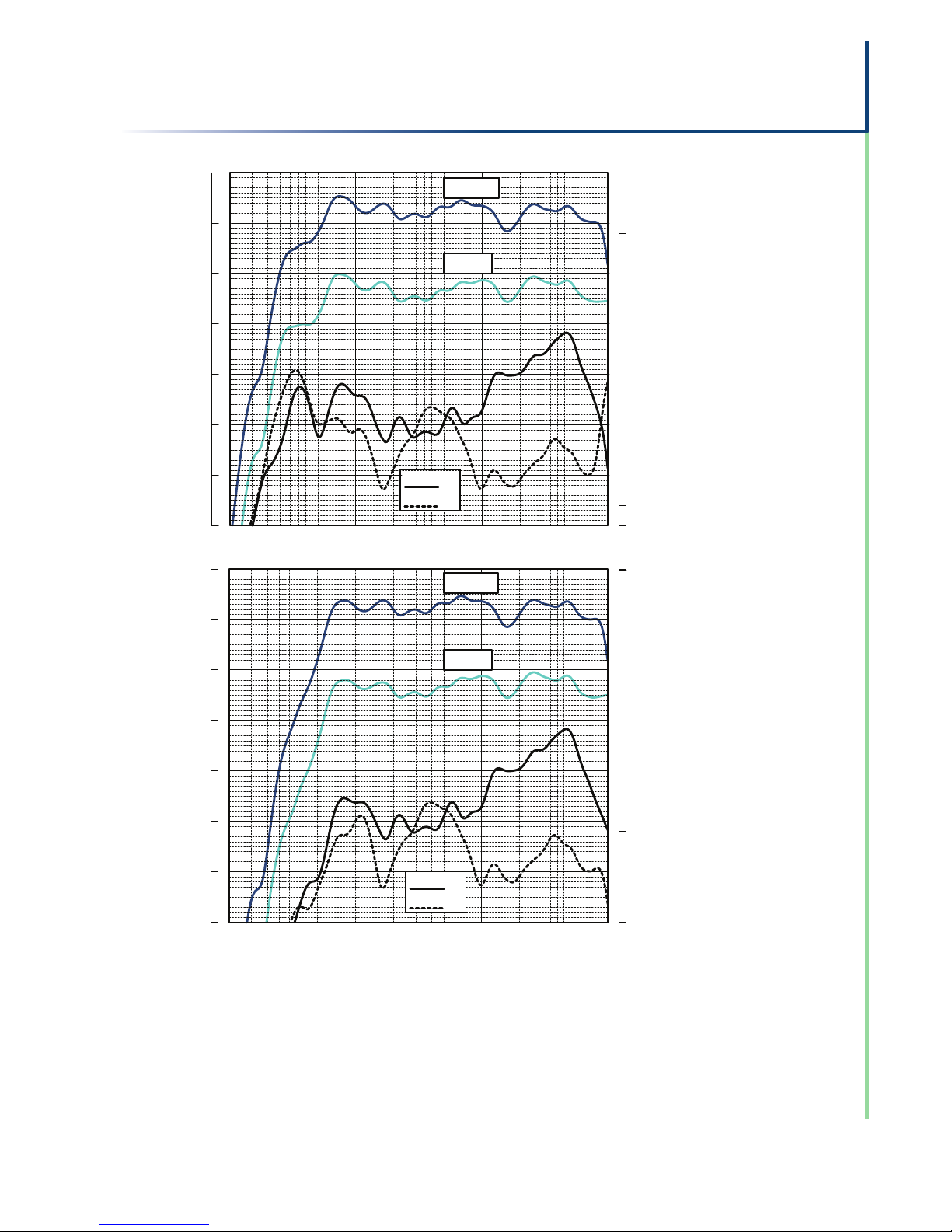
FREQUENCY
RESPONSE
(FULL RANGE)
FREQUENCY
RESPONSE
(HIGH PASS)
100 1 kHz 10 20
Frequency
50 200 500 2 5
20 Hz
0.2%
1.0%
Ref.
10% Power
Fundamental
1W/1M
Sensitivity
3rd Harmonic
10% Power
2nd Harmonic
10% Power
120
110
100
90
80
70
60
50
Sound Pressure Level in dB
Distortion %
100 1 kHz 10 20
Frequency
50 200 500 2 5
20 Hz
0.2%
1.0%
Ref.
10% Power
Fundamental
1W/1M
Sensitivity
3rd Harmonic
10% Power
2nd Harmonic
10% Power
120
110
100
90
80
70
60
50
Sound Pressure Level in dB
Distortion %
Impedance A constant current circuit was used to measure the impedance. Frequency response The frequency response
shown was obtained by feeding a swept sine wave through the system in a half space environment. The position of the
microphone was vertically on-axis at a distance of 2 metres, then scaled to represent 1 metre. 2nd & 3rd Harmonic Distortion
Distortion measurements were obtained using an Audio Precision harmonic distortion analysis system and comply with
AES recommendations for enclosure measurement (AES paper ANSI S4-26-1984). Data Conversion All graphs were digitally
generated using the APEX custom software system, designed to translate data derived from Audio Precision ‘System
One’ test equipment into AutoCAD™. This program enables graphical information to be plotted to a high degree of
accuracy.
NOTES ON
MEASUREMENT
CONDITIONS
 Loading...