

Page 1
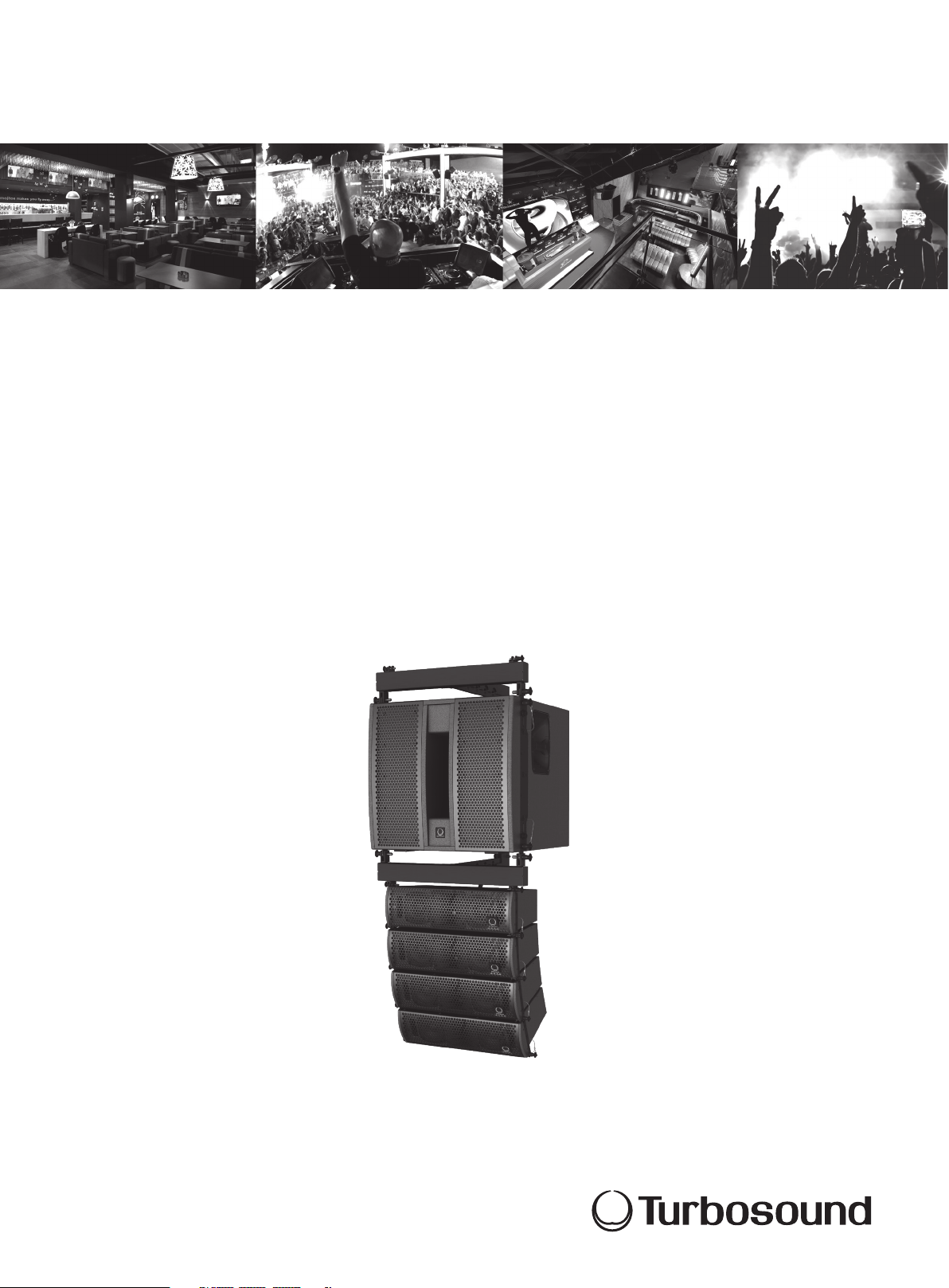
TLX LIVERPOOL SERIES
TLX212L
Compact Dual 12" Subwoofer for Portable and Fixed Installation Applications
TLX43
Compact Dual 2 Way 4" Line Array Element for Portable and
Fixed Installation Applications
TLX43-FLB
Fly Bar for TLX43 and TLX212L for Suspended or Ground Stacked Arrays
Rigging Manual
WARNING!
This rigging manual contains important safety information, and it must be kept in a safe place for future reference. It must be supplied with the equipment during the
original sale, rental, or re-sale, and all operators and users of the equipment must be made aware that this manual is available. Please visit our website
turbosound.com regularly and check for any updates to this manual.
Page 2

2 TLX43 and TLX212L Rigging Manual
Table of Contents
Important Safety Instructions ...................................... 3
Legal Disclaimer ............................................................. 3
Limited warranty ............................................................ 3
Chapter 1: Safety Information ......................................4
Chapter 2: Introduction ................................................. 6
Chapter 3: Assembling a TLX43 Array
on a TLX43-FLB Flybar ............................... 21
Chapter 4: Assembling one TLX212L Subwoofer
on a TLX43-FLB Flybar ............................... 27
Chapter 5: Assembling a TLX43 Array
with a TLX212L Subwoofer ....................... 33
Chapter 6: Groundstack of two
TLX212L Subwoofers ................................. 38
Chapter 7: Groundstack TLX212L Subwoofer
and TLX43 Array ......................................... 40
Chapter 8: Safety Inspection ....................................... 46
Chapter 9: Enclosure Quantities and
Combinations for TLX43-FLB
Flybar Suspension at 10:1, 7:1, 5:1
Design Factors ...........................................47
Manufacturer’s Declaration ........................................ 48
Page 3
TLX43 and TLX212L Rigging Manual 3
9. Do not defeat the safety purpose of the polarized
20. Please keep the environmental aspects of battery
or statement contained herein. Technical speci cations,
Important Safety Instructions
Terminals marked with this symbol carry
electrical current of su cient magnitude
to constitute risk of electric shock.
Use only high-quality professional speaker cables with
¼" TS or twist-locking plugs pre-installed. Allother
installation or modi cation should be performed only
by quali edpersonnel.
This symbol, wherever it appears,
alertsyou to the presence of uninsulated
dangerous voltage inside the
enclosure-voltage that may be su cient to constitute a
risk ofshock.
This symbol, wherever it appears,
alertsyou to important operating and
maintenance instructions in the
accompanying literature. Please read the manual.
Caution
To reduce the risk of electric shock, donot
remove the top cover (or the rear section).
No user serviceable parts inside. Refer servicing to
quali ed personnel.
Caution
To reduce the risk of re or electric shock,
do not expose this appliance to rain and
moisture. The apparatus shall not be exposed to dripping
or splashing liquids and no objects lled with liquids,
suchas vases, shall be placed on the apparatus.
Caution
These service instructions are for use
by quali ed service personnel only.
Toreduce the risk of electric shock do not perform any
servicing other than that contained in the operation
instructions. Repairs have to be performed by quali ed
servicepersonnel.
1. Read these instructions.
2. Keep these instructions.
3. Heed all warnings.
4. Follow all instructions.
5. Do not use this apparatus near water.
6. Clean only with dry cloth.
7. Do not block any ventilation openings. Install in
accordance with the manufacturer’s instructions.
8. Do not install near any heat sources such as
radiators, heat registers, stoves, or other apparatus
(including ampli ers) that produce heat.
or grounding-type plug. A polarized plug has two blades
with one wider than the other. A grounding-type plug
has two blades and a third grounding prong. The wide
blade or the third prong are provided for your safety. Ifthe
provided plug does not t into your outlet, consult an
electrician for replacement of the obsolete outlet.
10. Protect the power cord from being walked on or
pinched particularly at plugs, convenience receptacles,
and the point where they exit from the apparatus.
11. Use only attachments/accessories speci ed by
themanufacturer.
12. Use only with the
cart, stand, tripod, bracket,
or table speci ed by the
manufacturer, orsold with
the apparatus. When a cart
is used, use caution when
moving the cart/apparatus
combination to avoid
injury from tip-over.
13. Unplug this apparatus during lightning storms or
when unused for long periods of time.
14. Refer all servicing to quali ed ser vice personnel.
Servicing is required when the apparatus has been
damaged in any way, such as power supply cord or plug
is damaged, liquid has been spilled or objects have fallen
into the apparatus, the apparatus has been exposed
to rain or moisture, does not operate normally, or has
beendropped.
15. The apparatus shall be connected to a MAINS socket
outlet with a protective earthing connection.
16. Where the MAINS plug or an appliance coupler is
used as the disconnect device, the disconnect device shall
remain readily operable.
17. Correct disposal of this
product: This symbol indicates that
this product must not be disposed
of with household waste,
according to the WEEE Directive
(2012/19/EU) and your national
law. This product should be taken
to a collection center licensed for the recycling of waste
electrical and electronic equipment (EEE). The
mishandling of this type of waste could have a possible
negative impact on the environment and human health
due to potentially hazardous substances that are generally
associated with EEE. At the same time, your cooperation
in the correct disposal of this product will contribute to
the e cient use of natural resources. For more
information about where you can take your waste
equipment for recycling, please contact your local city
o ce, or your household waste collection service.
18. Do not install in a con ned space, such as a book
case or similar unit.
19. Do not place naked ame sources, such as lighted
candles, on the apparatus.
disposal in mind. Batteries must be disposed-of at a
battery collection point.
21. Use this apparatus in tropical and/or
moderate climates.
LEGAL DISCLAIMER
MUSIC Group accepts no liability for any loss which
may be su ered by any person who relies either
wholly or in part upon any description, photograph,
appearances and other information are subject to
change without notice. All trademarks are the property
of their respective owners. MIDAS, KLARK TEKNIK,
LAB GRUPPEN, LAKE, TANNOY, TURBOSOUND,
TC ELECTRONIC, TC HELICON, BEHRINGER, BUGERA
and DDA are trademarks or registered trademarks
of MUSIC Group IP Ltd. © MUSIC Group IP Ltd.
2017 All rights reserved.
LIMITED WARRANTY
For the applicable warranty terms and conditions
and additional information regarding MUSIC Group’s
Limited Warranty, please see complete details online at
music-group.com/warranty.
Page 4

4 TLX43 and TLX212L Rigging Manual
Chapter 1: Safety Information
1.1 Intended Use
The rigging components (TLX43-FLB ybar, rigging pins, drop links) shall only be used in conjunction with TURBOSOUND TLX43 loudspeakers and TLX212L subwoofers
as described in this manual.
1.2 Intended Use of this Manual
The instructions in this manual describe how to assemble various congurations of TLX43 loudspeaker cabinets, TLX212L subwoofers, and the TLX43-FLB, in readiness
for suspending or ground stacking.
These instructions shall only be used with the TLX43, TLX212L, and TLX43-FLB components.
The instructions do not show details of external lifting equipment and do not contain details of safe lifting procedures or installation.
Possession of these instructions and procedures does not imply authorisation for their use.
1.3 General Safety
The operation of your product as part of a suspended system, if installed incorrectly and improperly, can potentially expose persons to serious health risks and
even death. In addition, please ensure that electrical, mechanical and acoustic considerations are discussed with qualied and certied (by local, state or national
authorities) personnel prior to any installation.
Installation and setup should only be carried out by qualied and authorized personnel observing the valid local, state and other safety regulations applicable in your
country. If any parts or components are missing please contact your dealer before attempting to set up the system.
It is the responsibility of the person installing the assembly to ensure that the suspension/xing points are suitable for the intended use.
We also recommend you schedule TURBOSOUND line array training with our sales partners and applications team.
Equipment used to connect to the TURBOSOUND rigging system must be properly rated and must conform to the local, state and other safety regulations. Do not use
TURBOSOUND rigging with other types or brands of loudspeakers. This practice may compromise safety standards and MUSIC Group will not be responsible for damage
or injury so caused. Do not modify the rigging accessories, or use them in a way other than that described in this rigging manual. Rigging components supplied as part
of a complete assembly are non-interchangeable and must not be exchanged with the component parts of any other assembly.
Welding, or any other means of permanently xing rigging components to each other or to cabinet xing points is not allowed. Rigging components or assemblies
must only be xed to TURBOSOUND loudspeaker cabinets using the cabinet xing points.
MUSIC Group assumes no liability for any damage or personal injury resulting from improper use, installation or operation of the product. Regular checks must be
conducted by qualied personnel to ensure that the system remains in a secure and stable condition. Make sure that, where the product is suspended, the area
underneath the product is free of human trac. Do not suspend the product in areas which can be entered or used by members of the public.
1.4 Loudspeaker Cabling
Attach and suppor t the speaker cables from your ampliers to the loudspeaker cabinets, so that no signicant additional weight or lateral force is applied to the array
by the input wiring. Input cables or link cables should never be used to angle the array or used as rigging in any way.
1.5 Load Capacity and System Safety
The TLX43-FLB ybar is designed to suspend a maximum of 10 TLX43 loudspeaker cabinets, or 2 TLX212L subwoofers, or a mixed array of 1 TLX212L subwoofer with
4 TLX43 loudspeaker cabinets. The speakers may be own with any vertical splay angle conguration and from any of the pick points. This corresponds to
a Working Load Limit (WLL) of 94 kg with a design factor of 10:1.
TLX installation procedures and recommendations described in Chapters 3-5 are based on 10:1 design factor. TLX enclosure counts and combinations are also given for
5:1 and 7:1 design factors in Chapter 9. Check local regulations in order to comply with regional design factor requirements. Always refer to EASE FOCUS II modeling
software error and warning indications prior to installation.
1.6 Safety Inspections
Carefully inspec t rigging system components and cabinets for defects or signs of damage before proceeding to assemble the array to be own. If any parts are
damaged or suspect, or if there is any doubt as to the proper functioning and safety of the items DO NOT USE THEM and withdraw them from use immediately.
Refer to Chapter 8 for information about care maintenance and disposal.
Page 5
TLX43 and TLX212L Rigging Manual 5
1.7 Secondary Safeties
All loudspeakers own in theatres, studios or other places of work and entertainment must, in addition to the principle load bearing means of suspension, be provided
with an independent, properly rated, and securely attached secondary safety. Only steel wire ropes or steel chains of an approved construction and load rating shall be
used as secondary safeties. Plastic-covered steel wire ropes are not permitted for use as secondary safeties.
The secondary safety suspension must be independent of the primary suspension points and capable of carrying the total system weight. The additional safety device
must be mounted in a way that the array is caught by the safety device without any drop and swing in the event that the primary suspension fails.
1.8 Wind Loads
The loudspeakers must not be suspended or ground stacked in winds greater than:
Beaufort Scale 6 bft (39-49 km/h, 25-31 mph, 22-27 knots)
If the forecast or actual winds reach:
Beaufort Scale 8 bft (62-74 km/h, 39-46 mph, 34-40 knots)
1) Clear the area of personnel
2) Lower and secure the array
1.9 Operational Safety
The procedures require the use of two or more authorised persons.
Produce a lift plan: before any lift takes place, you must formulate a lift plan that describes the exact steps and procedures that will be carried out. The plan must be
shared with all assistants and stake-holders in the lift so that each person will understand their responsibilities.
Observe all instructions given on the respective instruction labels of the rigging components and loudspeakers.
When using chain hoists make sure nobody is directly underneath or in the vicinity of the array.
During assembly pay attention to the possible risk of crushing.
Wear suitable protective clothing.
Safety Logo Description Safety Logo Description Safety Logo Description
Protective Headwear
shall be worn
Protective Footwear
shall be worn
1.10 Safety Notices in this manual
WARNING
This indicates advice that if not followed, may lead to permanent injury or death.
CAUTION
This indicates advice that if not followed, may lead to damage to the equipment.
NOTE
This indicates extra advice that may be useful when performing the procedures.
Protective Eyewear
shall be worn
Practice Safe Lifting
Protective Gloves
shall be worn
Page 6
6 TLX43 and TLX212L Rigging Manual
Chapter 2: Introduction
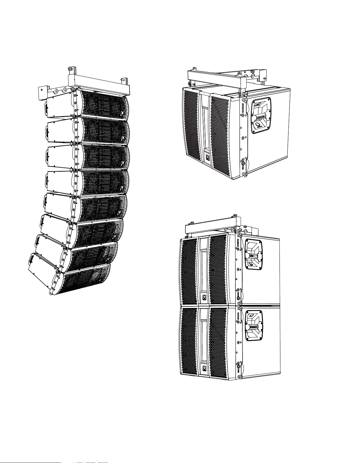
2.1 Typical Congurations
TLX43 Array (See Chapter 3) TLX212L (See Chapter 4)
TLX212L Pair (See Chapter 4)
Page 7
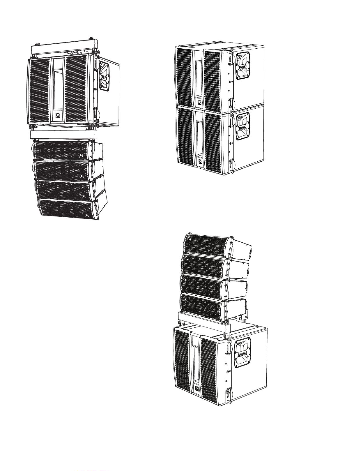
TLX43 and TLX212L Rigging Manual 7
TLX212L and TLX43 Array (See Chapter 5) Two TLX212L Subwoofer Groundstack (See Chapter 6)
TLX212L and TLX43 Array Groundstack (See Chapter 7)
Page 8
8 TLX43 and TLX212L Rigging Manual
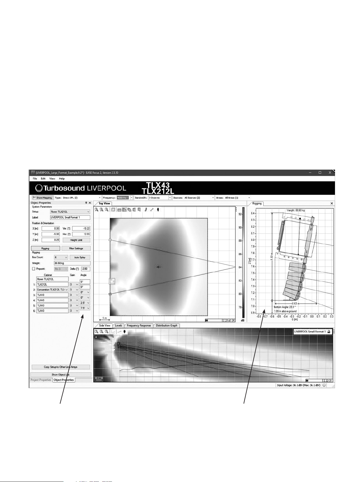
2.2 Rigging and Acoustic Simulation Software
The EASE FOCUS II software allows you to congure the system for optimal performance and coverage in the venue.
The software can be downloaded from http://www.afmg.eu/index.php/products.html
The quantity of cabinets can be varied, the angles of each cabinet can be adjusted, and the SPL coverage calculated for any conguration.
Once an optimum system has been designed using the EASE FOCUS II software, the angles of each TLX43 cabinet should be noted, as well as the correc t suspension
hole on the TLX43-FLB ybar, where your bow shackle would be tted for single-point suspension. For two-point suspension, pick point holes #1 and #5 can be utilized
in conjunction with front and rear chain motors to obtain the desired array site angle.
The EASE FOCUS II screenshot below is for a typical TLX43 conguration. Check the “RIGGING” Tab and note installation parameters such as: array weight, bot tom
element elevation above ground level, bottom enclosure angle.
Note the angle of each TLX43 cabinet in the “Object Proper ties” Tab.
WARNING
ERROR AND WARNING INDICATIONS ARE GIVEN IN THE OBJECT PROPERTIES WINDOW IF WORKING LOAD LIMITS ARE EXCEEDED AT 10:1, 7:1 OR 5:1 DESIGN FACTORS.
HEED THESE WARNINGS AT ALL TIMES IN ACCORDANCE WITH LOCAL REGULATIONS.
EASE FOCUS II Typical Screenshot for a TLX43 Array
TLX43 Cabinet Angles
Rigging Tab Shows the layout graphically,
and indicates the correct suspension pick point
to choose on the ybar.
Page 9
TLX43 and TLX212L Rigging Manual 9
2.3 TLX43 Cabinet Angles
The angle of each TLX43 cabinet relative to the cabinet above it, is varied by selecting one of four mounting holes in the rear mounting bracket.
These are labeled 0, 2.5, 5.0, and 7.5 degrees.
Degrees
0
2.5
5.0
7.5
Page 10

10 TLX43 and TLX212L Rigging Manual
2.4 Weights
Item Quantity Weigh t (kg) Weight (lbs)
TLX43 1 8 17. 6
2 16 35.3
3 24 52.9
4 32 70.6
5 40 88.2
6 48 106
7 56 123
8 64 141
9 72 159
10 80 176
Item Quantity Weig ht (kg) Weight (lbs)
TL X212L 1 43 94.8
2 86 190
Item Quantity Weight (kg) Weight (lbs)
TLX43- FLB 1 6.8 15
2 13.6 30
2.5 TLX43-FLB Flybar Working Load Limit (WLL)
Item WLL (kg) WLL ( lbs) Design Factor
94 207 10:1
TLX43- FLB
134 296 7:1
188 414 5:1
2.6 TLX43-FLB Flybar Safety Warning Label
Page 11
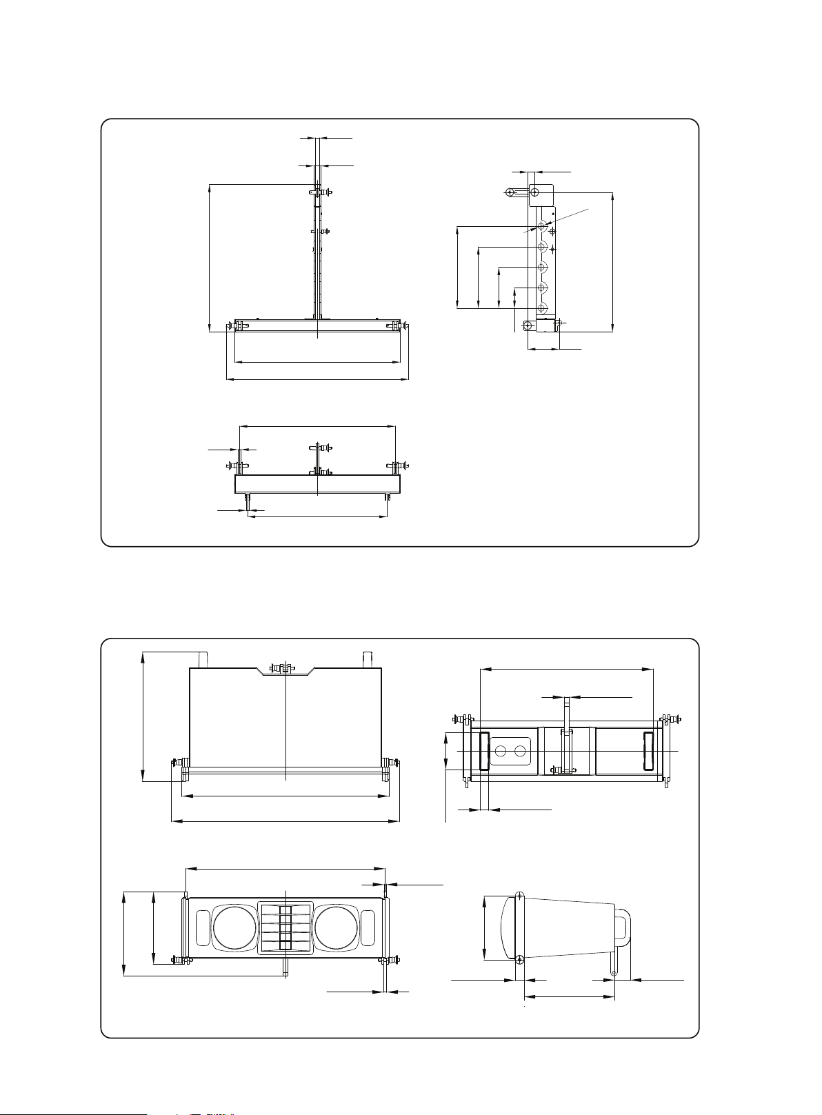
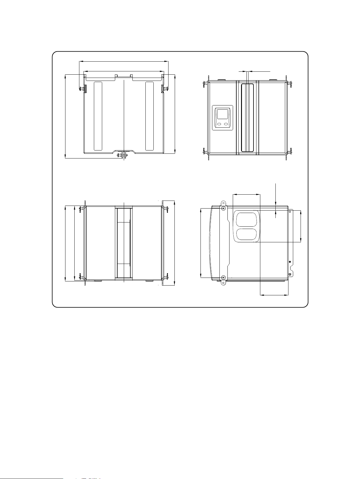
2.7 TLX43-FLB Flybar Dimensions
See Chapter 8 for information regarding inspection, care, and maintenance.
12 [0.5]
TLX43 and TLX212L Rigging Manual 11
475.5 [18.7]
9 [0.4]
9 [0.4]
22 [0.9]
CL
534 [21]
588 [23.1]
TOP
501 [19.7]
CL
450 [17.7]
FRONT
264 [10.4]
198 [7.8]
23.3 [0.9]
Ø20 [Ø0.8]
450 [17.7]
132 [5.2]
66 [2.6]
102 [4]
SIDE
2.8 TLX43 Cabinet Dimensions
See Chapter 8 for information regarding inspection, care, and maintenance.
CL
290 [11.4]
465 [18.3]
512 [20.2]
TOP
448 [17.6]
163 [6.4]
189 [7.5]
CL
FRONT
7 [0.3]
5 [0.2]
84 [3.3]
20 [0.8]
388 [15.3]
12 [0.5]
CL
19 [0.7]
BACK
143 [5.6]
35 [1.4]
203 [8]
SIDE
Page 12
12 TLX43 and TLX212L Rigging Manual
2.9 TLX212L Subwoofer Dimensions
See Chapter 8 for information regarding inspection, care, and maintenance.
576 [22.7]
518 [20.4]
12 [0.5]
542 [21.3]
482 [19]
488 [19.2]
TOP
CL
FRONT
511 [20.1]
547 [21.5]
448 [17.6]
BACK
175 [6.9]
SIDE
29 [1.2]
205 [8.1]
182 [7.2]
Page 13
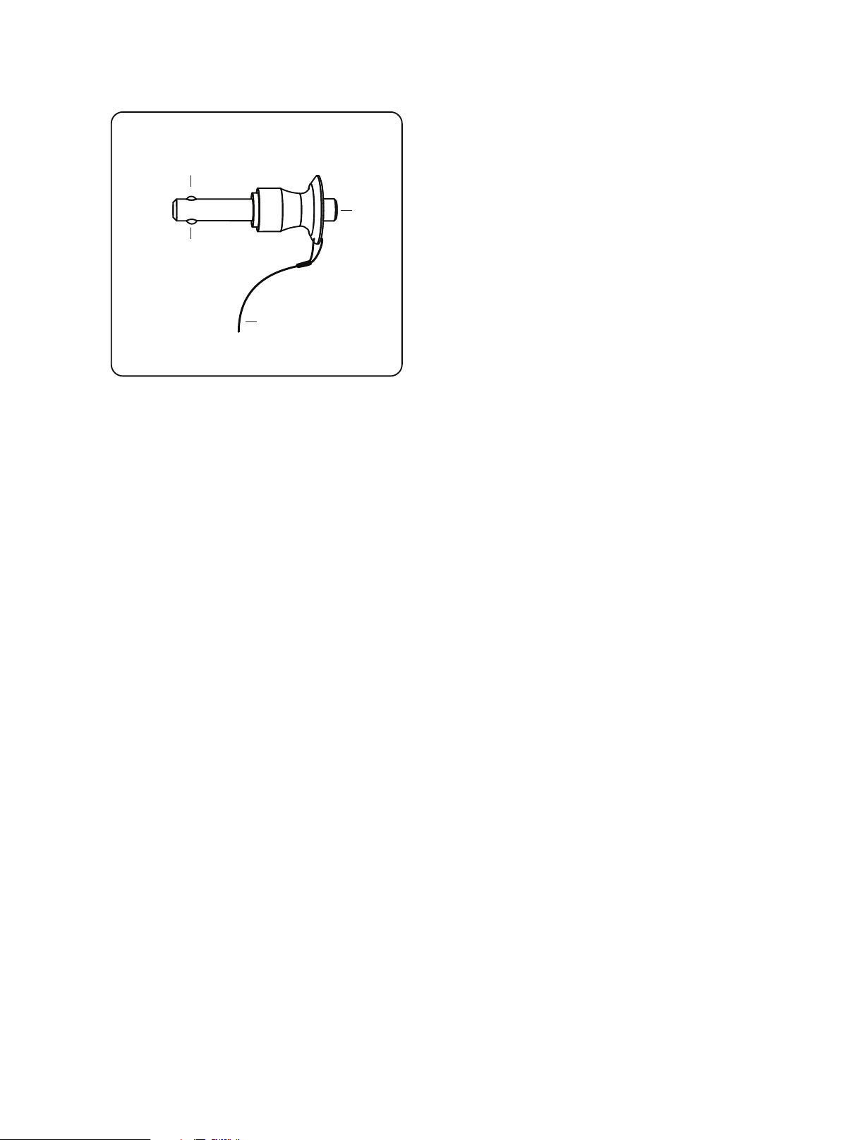
2.10 Rigging Pins
See Chapter 8 for information regarding inspection, care, and maintenance.
1
2
1
3
TLX43 and TLX212L Rigging Manual 13
These pins are the fundamental mechanical fastener for the assembly of the
TLX43-FLB ybar, TLX43 cabinet, and the TLX212L subwoofer.
1. Spring Balls – These are locking devices that prevent the pin from pulling
out once it has been inserted.
2. Spring Release – Press this button in and the spring balls (1) will
unlock and allow the pin to be inser ted into the mounting holes and lugs.
Release this button and the spring balls will lock and prevent the pin from
pulling back out.
3. Lanyard – These prevent the pins from being easily lost.
WARNING
BEFORE EVERY USE, INSPECT ALL PINS FOR DAMAGE, AND VERIFY THE CORRECT
OPERATION OF THE SPRING LOCKING MECHANISM. DO NOT USE ANY PINS THAT
SHOW SIGNS OF DAMAGE. FAILURE TO FOLLOW INSTRUCTIONS MAY CAUSE
PERMANENT INJURY OR DEATH.
WARNING
BEFORE EVERY USE, MAKE SURE THAT ALL PINS ARE CLEAN AND FREE FROM
DIRT AND DEBRIS THAT MAY INTERFERE WITH THE CORRECT OPERATION OF THE
SPRING LOCKING MECHANISM. FAILURE TO FOLLOW INSTRUCTIONS MAY CAUSE
PERMANENT INJURY OR DEATH.
Page 14
14 TLX43 and TLX212L Rigging Manual
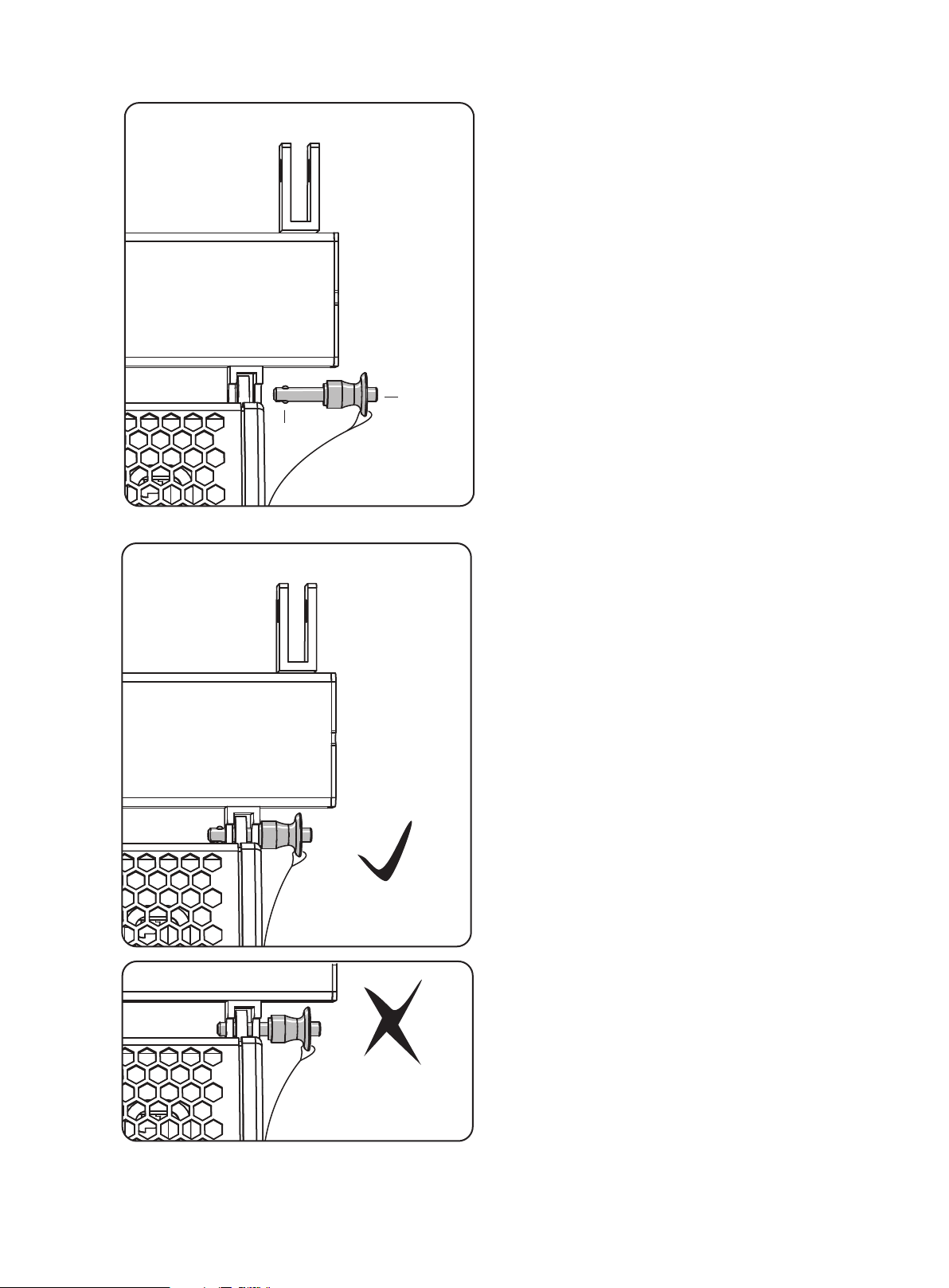
2.10.1 Rigging Pin Installation
1
Pin Installation
The following example shows how to use a pin to join the lugs of a TLX43
cabinet and a TLX43-FLB ybar. Exact details of the connec tions for various
congurations are given in the various chapters of this manual.
1. Support the weight of the components to be joined.
2. Align the top lug of the TLX43 cabinet with the bottom lug of the TLX43FLB ybar. Align the lug holes so the pin can pass through and join
them together.
3. Press the button (2) at the end of the pin, and insert the pin in as far as
it will go. The spring balls(1) will retract while the button is being held,
allowing the pin to pass through the holes.
4. Release the button (2) when the pin is fully inserted.
5. Check the pin is correctly inserted as far as it will go, and that the spring balls
are visible. Check that the components being connected have been correctly
2
captured together by the pin.
6. With the weight of the components still supported, and without pressing
the button (2), try to pull on the pin sharply, to check it is secured in position
by the spring ball locking mechanism.
Pin Removal
1. Support the weight of the components to be disconnected.
2. Press the button (2) and pull out the pins joining the components together.
3. Carefully separate the components.
Not inserted fully and
spring balls are not visible
Page 15
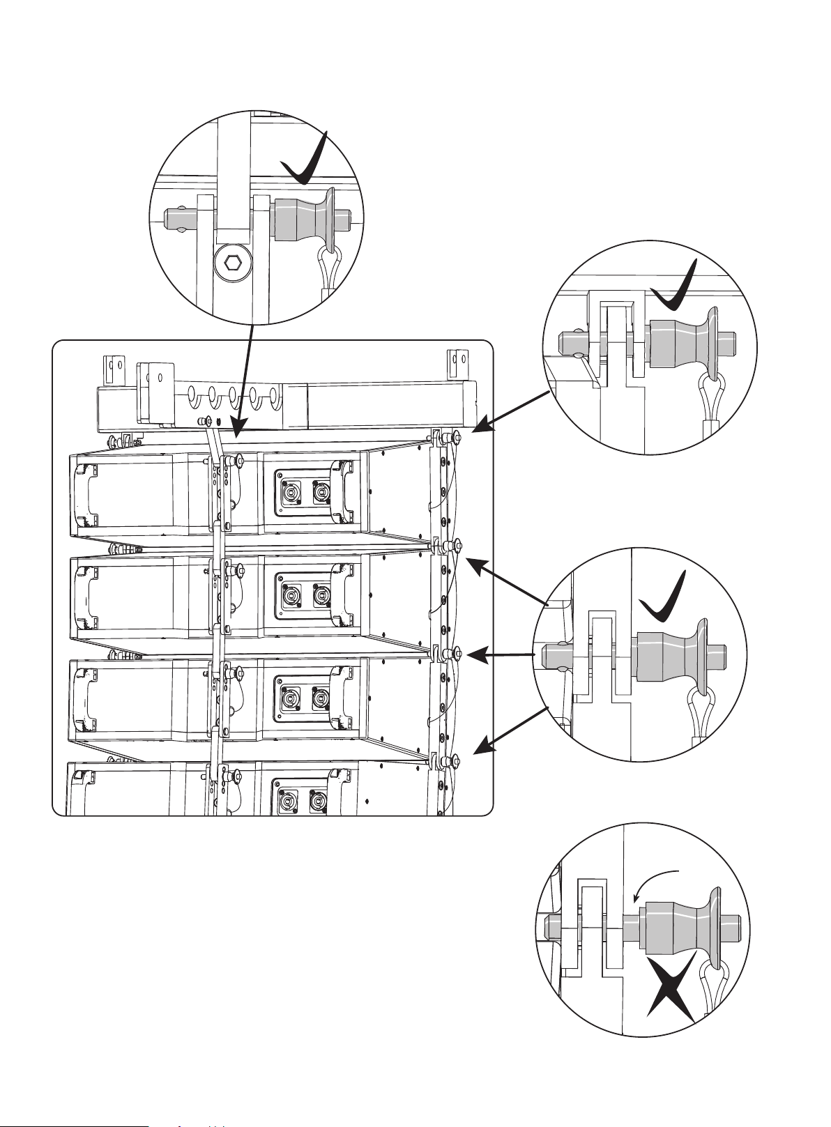
2.10.2 Typical Locations where Rigging Pins are used
PINS CORRECTLY INSERTED, ALL THE WAY IN
TLX43 and TLX212L Rigging Manual 15
PINS CORRECTLY INSERTED, ALL THE WAY IN
WARNING
VERIFY THAT EACH PIN IS CORRECTLY INSERTED, AND THAT EACH PIN CANNOT BE PULLED OUT WITHOUT
PRESSING THE RELEASE BUTTON FIRST. FAILURE TO FOLLOW INSTRUCTIONS MAY CAUSE PERMANENT
INJURY OR DEATH.
PINS CORRECTLY INSERTED, ALL THE WAY IN
GAP !
PINS INCORRECTLY INSERTED (NOT INSERTED
FULLY AND SPRING BALLS ARE NOT VISIBLE)
Page 16
16 TLX43 and TLX212L Rigging Manual
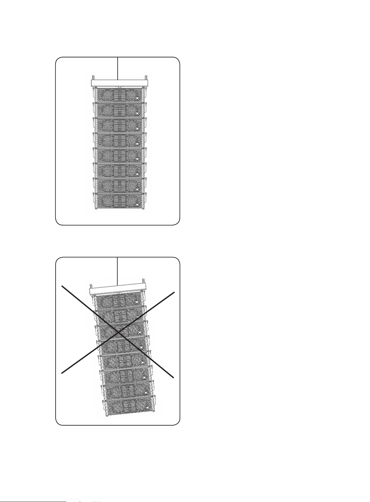
2.11 Vertical Orientation
CORRECT INSTALLATION
Vertical Orientation Only!
The mechanical design of the TLX43 cabinet, TLX212L subwoofer, and the
TLX43-FLB ybar uses lugs, links, and pins to assemble the various components.
The mechanical strength comes from the cabinet's metal side pieces and the
pins, and not through the wooden cabinets. The cabinets are supported vertically
below each other, and vertically below the ybar.
WARNING
THE ASSEMBLY MUST BE ORIENTED SO THAT THE SIDES OF THE CABINETS AND
SUBWOOFER ARE ALWAYS KEPT IN THE VERTICAL PLANE. FAILURE TO DO THIS
MAY CAUSE STRAIN AND FAILURE OF THE MECHANICAL STRUCTURE, LEADING TO
POSSIBLE PERMANENT INJURY OR DEATH.
INCORRECT INSTALLATION
WARNING
THIS ILLUSTRATION SHOWS AN INCORRECT INSTALLATION, WHERE THE SIDES OF
THE CABINETS ARE NOT IN THE VERTICAL PLANE. THIS MAY CAUSE STRAIN AND
FAILURE OF THE MECHANICAL STRUCTURE, LEADING TO POSSIBLE PERMANENT
INJURY OR DEATH.
WARNING
THE TLX43 CABINETS, TLX212L SUBWOOFERS, AND TLX43-FLB FLYBAR SHALL NOT
BE CLIMBED UPON. THIS MAY CAUSE STRAIN AND FAILURE OF THE MECHANICAL
STRUCTURE, LEADING TO POSSIBLE PERMANENT INJURY OR DEATH.
Page 17

TLX43 and TLX212L Rigging Manual 17
2.12 TLX212L Subwoofer
Mounting Components
Mounting Links Out
9
8 7
Mounting Links In
The TLX212L subwoofer has two retractable mounting links at the bottom (6),
one mounting hole at the rear top (9), and a drop-down link (8) at the rear
bottom. The TLX43-FLB ybar is supplied with two drop down links that t in
two locations (1) on top of the subwoofer. These mounting points allow the
subwoofer to be connected to the TLX43-FLB ybar in various congurations,
1
1
4
5
6
or joined to another TLX212L.
1. Location for Top Mounting Links – TLX43-FLB ybar is supplied with
2
3
two drop down links that t in these two locations. The bottom links (6) of a
second TLX212L subwoofer can also t here.
2. Top Pins – Secures the mounting links of the TLX43-FLB ybar (if used) or
the drop down links of a second TLX212L subwoofer.
3. Slot – TLX43-FLB ybar is supplied with two drop down links, and two bolts
that t into these slots.
4. Bottom Bolts – These allow the bottom mounting links (6) to be
positioned up or down, by sliding in the slot, then securing with the bottom
pin (5).
5. Bottom Pins – Secures the bottom mounting link (6) in the down or
up position.
6. Bottom Mounting Links – These connect to the top of a second TLX212L
subwoofer or the mounting lugs of a TLX43-FLB ybar that can be tted
below the subwoofer. Fitting the ybar beneath the subwoofer allows an
array of up to 4 TLX43 cabinets to be hung below the subwoofer.
7. Rear Pin – This is used to connect the drop down link (8) to a subwoofer
below, or to the rear mounting hole of a TLX43-FLB ybar at tached beneath
the subwoofer.
8. Rear Drop-Down Link – This is used to connec t to the rear mounting hole
(9) of a second TLX212L subwoofer, or to connect to the rear mounting hole
of a TLX43-FLB ybar attached beneath the subwoofer.
9. Rear Mounting Hole – This is used to connect to the drop-down
link (8) of a TLX212L subwoofer above it, or to the drop-down link of a
TLX43-FLB ybar.
Page 18

18 TLX43 and TLX212L Rigging Manual
Degrees
0
2.5
5.0
7.5
2.13 TLX43 Cabinet Mounting Components
21
12
3
3
The TLX43 cabinet has two xed mounting lugs (2) at the top, two xed
mounting lugs (3) at the bottom, a choice of four mounting holes (4) at the rear
top, and a drop-down link (6) at the rear bottom. These allow the TLX43 cabinets
to be connected together, and attached to the TLX43-FLB ybar.
1. Front Pins – These are used to secure the top mounting lugs (2) of the
TLX43 cabinet to the bottom lugs (3) of the TLX43 cabinet above, or to the
bottom mounting lugs of the TLX43-FLB ybar. They are attached with
lanyards to prevent loss.
2. Top Mounting Lugs – These connect to the bottom lugs (3) of the TLX43
cabinet above, or to the bottom mounting lugs of the TLX43-FLB ybar.
3. Bottom Mounting Lugs – These connect to the top lugs (2) of the TLX43
cabinet below.
6
54
Degrees
0
2.5
5.0
7.5
4. Rear Mounting Holes – These are used to connect the rear drop-down
link (6) of the TLX43 cabinet above, or the drop-down link of the TLX43-FLB
ybar. The angle of the cabinet is dened by choosing one of these four
holes. They are marked as follows, starting with the top hole: 0 , 2.5, 5.0, and
7.5 degrees.
5. Rear Pin – This is used to secure the rear drop-down link (6) of the TLX43
cabinet above, or the drop-down link of the TLX43-FLB ybar, to the selected
rear mounting hole (4). If the drop-down link (6) is not in use, then the pin is
used to secure it using the bottom mounting hole (7.5 degrees).
7
6
8
6. Drop-Down Link – This connects to the rear mounting hole (4) of the TLX43
cabinet below it.
7. Circlip – A circlip (7) holds the pivot pin (8) in place, and prevents the pivot
pin and the drop down link (6) from falling out.
8. Pivot Pin – This pin holds the drop-down link (6) in place and allows it to
rotate in the up or down position. A circlip (7) holds the pivot pin in place.
Page 19

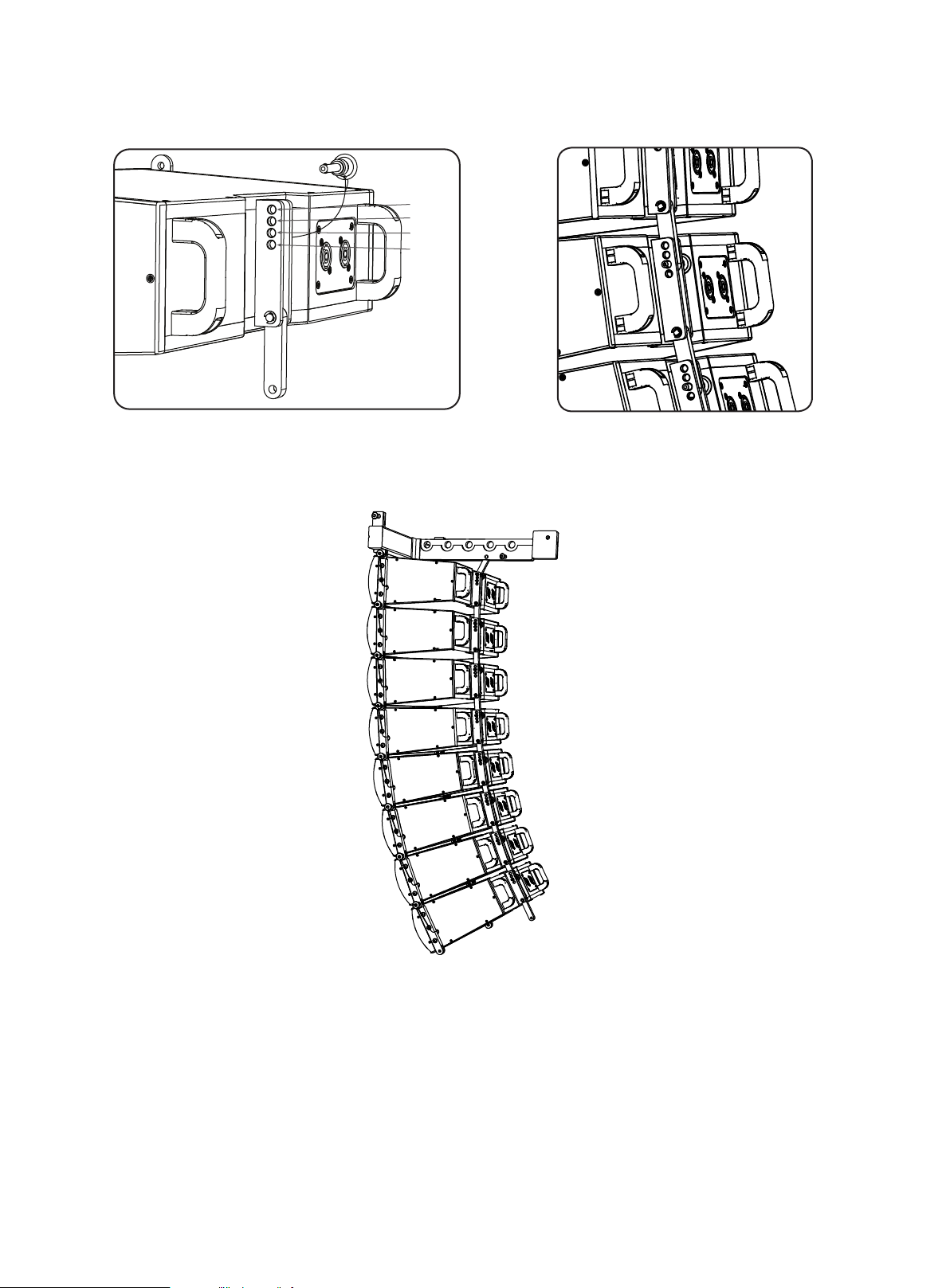
2.14 TLX43-FLB Flybar Mounting Components
3
1
1
2
TLX43 and TLX212L Rigging Manual 19
The TLX43-FLB ybar shall only be used with TLX43 cabinets and TLX212L
subwoofers. One side is used to connect to a TLX43 cabinet, the other side is used
to connect to the top (or bottom) of a TLX212L subwoofer.
2.14.1 Use with TLX43 Cabinet
1. Mounting Lugs – These connect the ybar to the top lugs of the
TLX43 cabinet. The connections are secured using the front pins of the
TLX43 cabinet.
2. Drop-Down Link – This connects the ybar to the rear mounting point of
the TLX43 cabinet. It has a xed pivot and circlip. The connection is secured
using the rear pin of the TLX43 cabinet.
3. Suspension Points – These 20 mm diameter holes are used to attach
a bow shackle or similar lifting equipment for suspending the assembly.
Use the EASE FOCUS II software to determine the correct pick point for each
conguration.
Suspend the array by attaching one or more bow shackles or similar lifting
devices with a pin diameter (D) to t the 20 mm suspension pick point.
Typically, manufacturers of bow shackles provide suitable devices with
pin diameters between 11 mm and 19 mm, and with work loads between
1 tonnes and 3.25 tonnes.
Installation and setup should only be carried out by qualied and authorized
personnel observing the valid national Rules for the Prevention of Accidents
(RPA). Refer to Chapter 1 for more details.
Typical Bow Shackle
NOTE
The TLX43-FLB ybar is supplied with hardware for use with a TLX212L
subwoofer. See the next page for more details. The hardware can be removed
and kept in a safe place if a TLX212L subwoofer is not used.
Page 20

20 TLX43 and TLX212L Rigging Manual
2.14.1 TLX43-FLB Flybar (continued)
1
2
3
2.14.2 Use with TLX212L Subwoofer
6
1. Front Pins* – These secure the mounting lugs (2) of the ybar either to the
mounting links (3) that t into the top of the TLX212L subwoofer, or to the
retractable links at the bottom of the TLX212L subwoofer.
2. Mounting Lugs – These connect the ybar either to the mounting links (3)
that t into the top of the TLX212L subwoofer, or to the retractable links at
the bottom of the TLX212L subwoofer.
3. SUB Links – These are used to connect the ybar to the top of the TLX212L
5
4
2
1
subwoofer.
4. Sub Drop Link – This is used to connect the ybar to the rear mounting
point of a TLX212L subwoofer. (This is not used if mounting to the bottom of
a TLX 212L.)
5. Rigging Pins* – Rigging pins are connected to the removable sub drop
link (5) by captive lanyard. These pins are used to secure the rear drop link to
the rear mounting hole of the ybar, and to secure the other end to the rear
mounting point of a TLX212L subwoofer.
* This hardware is supplied with the TLX43-FLB ybar.
3
TLX43-FLB Flybar on top of a TLX212L Subwoofer (with mounting links
(3) and bolts (4) already tted to the subwoofer)
TLX43-FLB Flybar mounted on top and bottom of a TLX212L Subwoofer
Page 21

TLX43 and TLX212L Rigging Manual 21
Chapter 3: Assembling a TLX43 Array on a TLX43-FLB Flybar
The following procedure shows how to build an array of TLX43 cabinets by
adding them one at a time.
Alternatively, cabinets can be pre-assembled into groups of four, and then
connected to the ybar at a later time. This method is shown in procedure 3.2.
The system is suspended using a TLX43-FLB ybar that attaches to your
lifting system.
The top TLX43 cabinet connects to two front lugs on the ybar, and one rear
drop-down link.
Four rear mounting holes on the back of the TLX43 allow the cabinet angle to
be selected from 0, 2.5, 5.0, or 7.5 degrees. To set the site angle of the top TLX43
element parallel to the TLX43-FLB, select the 0 degree hole to attach the top
TLX43 enclosure to the ybar.
WARNING
DO NOT EXCEED A TOTAL QUANTITY OF 10 TLX43 CABINETS FOR ONE TLX43-FLB
3.0.1 Required Components
Item Quantity
TLX43-FLB Flybar 1
TLX43 Cabinet 10 (maximum)
3.0.2 Preparation
Use the EASE FOCUS II software application to design your system to suit the
venue. This will calculate which ybar mounting hole to attach your bow shackle,
and at which angle to set each TLX43 cabinet to achieve optimum coverage.
3.0.3 Location
Move the rst TLX43 cabinet so it is sitting upright on a safe at surface,
directly below the suspension point.
FLYBAR. FAILURE TO FOLLOW INSTRUCTIONS MAY CAUSE PERMANENT INJURY
OR DEATH.
3.0.5 Personnel
The following procedures shall be undertaken by experienced, certied,
qualied, and authorised personnel only. The procedures require the use of three
or more authorised persons.
Protective Headwear shall be worn
Protective Footwear shall be worn
3.0.4 Measured Weights
Item Quantity Total Wei ght including o ne TLX43-FLB Flybar
TLX43 1 14.8 kg 32.6 lbs
2 22.8 kg 50.3 lbs
3 30.8 kg 6 7.9 lb s
4 38. 8 kg 85.5 lbs
5 46.8 kg 103 l bs
6 54. 8 kg 12 1 lbs
7 62.8 kg 138 l bs
8 70. 8 kg 156 lbs
9 78.8 kg 174 lb s
10 86.8 kg 191 lb s
TLX43-FLB Flybar Working Load Limit (WLL)
Item Working Load Limit (WLL)
TLX43- FLB 94 kg 207.23 lbs
Protective Gloves shall be wor n
Protective Eyewear shall be worn
Practice Safe Lifting
Page 22

22 TLX43 and TLX212L Rigging Manual
Procedure 3.1 Connecting TLX43 Cabinets to the TLX43-FLB Flybar
1. The TLX43-FLB ybar comes with extra components (marked* in this
drawing) that are only used when rigging the TLX212L subwoofer.
Remove these components from the ybar and keep them together in a
safe place.
2. Prepare the rst TLX43 cabinet, by pulling out the front two pins (1)
from the top mounting lugs (2), and remove the rear pin (4) from the rear
mounting holes (3). The rear drop-down link (5) of the cabinet will
drop down.
1 1 43
2 2
*
*
1st
5
3. Remove the small rigging pin from its storage position on the ybar and
allow the ybar's captive rear drop link to drop down. Re-inser t the rigging
pin in its storage location on the TLX43-FLB.
Carefully lower the TLX43-FLB ybar on top of the rst TLX43 cabinet and
align the ybar’s mounting lugs (6) with the two top mounting lugs (2)
6
1
of the cabinet.
4. Insert the front two pins (1) to secure the front mounting lugs of the ybar
(6) with the two top mounting lugs (2) of the TLX43 cabinet.
CAUTION:
Support the rear of the ybar until the rear drop-down link (7) of the ybar is
connected in the next step.
1
Take care not to trap your ngers between components.
Page 23

TLX43 and TLX212L Rigging Manual 23
Degrees
0
2.5
5.0
7.5
5. Align the ybar's drop-down link (7) with the desired hole (3) in the TLX43
rear bracket. The holes are marked with the angle. Choose the correct hole
that corresponds to the angle recommended by EASE FOCUS II software for
the rst TLX43 cabinet. Insert the rear pin (4).
Note: normally the 0 degree hole is selected to attach the top TLX43
enclosure to the TLX43-FLB in order to set the site angle of the top element
7
4
3
parallel to the ybar. This allows the TLX43-FLB to serve as a visual reference
for checking array focus on the audience area, i.e., if you can see the
top of the TLX43-FLB then you are outside the vertical coverage pattern
of the array.
Double check that all pins are correctly inserted,
before proceeding further.
1 1 43
2 2
2nd
8
8
1st
2
2nd
6. Attach the bow shackle or other lifting equipment securely to the ybar
mounting hole recommended by the EASE FOCUS II software, then attach
the hook and chain. Carefully raise the ybar to a reasonable working height
to allow attaching the next cabinet.
7. Prepare the next TLX43 cabinet, by pulling out the front two pins
(1) from the top mounting lugs (2), and remove the rear pin (4) from
the rear mounting holes (3). The rear drop-down link (5) of the cabinet
will drop down.
5
CAUTION
Check that the drop down link (5) and its pivot pin and circlip and are all present,
clean, and in good condition. Check that the circlip is correctly holding the pivot
pin in place, and preventing it and the drop down link from falling out.
8. Lift this TLX43 cabinet until the front top mounting lugs (2) align with the
two bottom mounting lugs (8) of the TLX43 cabinet above it.
Page 24

24 TLX43 and TLX212L Rigging Manual
Procedure 3.1 continued
1
9. Insert the front two pins (1), to secure the front top mounting lugs (2) of this
TLX43 cabinet to the two bottom mounting lugs (8) of the TLX43 cabinet
above it.
CAUTION:
Support the rear of the cabinet until the rear drop-down link (5) is connected
1
(nex t step).
Take care not to trap your ngers between components.
10. Align the rear drop-down link (5) of the top TLX43 cabinet with the desired
mounting hole (3) in the rear of the TLX43 cabinet below it. The holes are
marked with the angle. Choose the correct hole that corresponds to the
angle recommended by EASE FOCUS II software for this TLX43 cabinet.
Insert the rear pin (4).
1st
2nd
Double check that all pins are correctly inserted, before
5
3
4
proceeding further.
11. The addition of other TLX43 cabinets is performed by repeating steps 7
through 10 for each additional cabinet.
WARNING
DO NOT EXCEED A TOTAL QUANTITY OF 10 TLX43 CABINETS FOR ONE TLX43-FLB
FLYBAR. FAILURE TO FOLLOW INSTRUCTIONS MAY CAUSE PERMANENT INJURY
OR DEATH.
NOTE
Disassembly is the reverse of assembly.
Page 25

TLX43 and TLX212L Rigging Manual 25
Procedure 3.2: Adding a group of four TLX43 Cabinets to the TLX43-FLB Flybar
3
4 4 3 6
Groups of four cabinets can be pre-assembled using Procedure 3.1, steps 7
through 10, and then connected to the TLX43-FLB ybar as an assembled group
of four just prior to ying.
The TLX43 cabinets connect to each other using the top and bottom front
mounting links, and the rear drop-down link.
1. Prepare the top TLX43 cabinet of the group of four, by pulling out the front
two pins (3) from the top mounting lugs (4).
2. Carefully lower the TLX43-FLB ybar onto the top TLX43 cabinet and align
the front mounting lugs (8) of the ybar with the two top mounting lugs (4)
of the cabinet.
8
4
9
WARNING
5
DO NOT EXCEED A TOTAL QUANTITY OF 4 TLX43 CABINETS FOR EACH
PRE-ASSEMBLED GROUP. FAILURE TO FOLLOW INSTRUCTIONS MAY CAUSE
PERMANENT INJURY OR DEATH.
WARNING
DO NOT FLY THE PRE-ASSEMBLED GROUPS OF TLX43 CABINETS WITHOUT THE
TLX43-FLB FLYBAR. FAILURE TO FOLLOW INSTRUCTIONS MAY CAUSE PERMANENT
INJURY OR DEATH.
Page 26

26 TLX43 and TLX212L Rigging Manual
Procedure 3.2 continued
3
3. Insert the front two pins (3) to secure the front mounting lugs of the ybar
(8) with the two top mounting lugs (4) of the TLX43 cabinet.
CAUTION:
Do not let the TLX43 cabinet assembly hang from the two front lugs only.
This may cause damage to the front lugs. Always support the weight of the
cabinets until the rear drop-down link (9) is secured with its pin (6) in the
next step.
4. Align the ybar's drop-down link (9) with the desired hole (5) in the TLX43
rear bracket. The holes are marked with the angle. Choose the correct hole
that corresponds to the angle recommended by EASE FOCUS II software for
the top TLX43 cabinet.
Note: normally the 0 degree hole is selected to attach the top TLX43
enclosure to the TLX43-FLB in order to set the site angle of the top element
parallel to the ybar. This allows the TLX43-FLB to serve as a visual reference
for checking array focus on the audience area, i.e., if you can see the top of
the TLX43-FLB then you are outside the vertical coverage pattern
of the array.
5. Insert the rear pin (6) into the hole (5) to capture the hole in the drop-down
link (9).
6. The angles of the lower three cabinets can be adjusted by rst supporting
their weight, and then moving the rear pins (6) to the desired holes.
Double check that all pins are correctly inserted.
NOTE
Disassembly is the reverse of assembly.
Page 27

TLX43 and TLX212L Rigging Manual 27
Chapter 4: Assembling one TLX212L Subwoofer on a TLX43-FLB Flybar
The following procedure describes how to assemble a single TLX212L subwoofer
to the TLX43-FLB ybar.
The TLX43-FLB ybar is attached to the top of the TLX212L subwoofer, using 2
front pins, 2 mounting links, and a rear drop-down link, supplied with
the TLX43-FLB ybar.
WARNING
DO NOT EXCEED A TOTAL QUANTITY OF 2 TLX212L SUBWOOFERS FOR
ONE TLX43-FLB FLYBAR. FAILURE TO FOLLOW INSTRUCTIONS MAY CAUSE
PERMANENT INJURY OR DEATH
4.0.1 Required Components
Item Quantity
TLX43-FLB Flybar 1
TLX212L Subwoofer 2 (max)
4.0.2 Location
Move the TLX212L subwoofer so it is sitting upright on a safe at surface, directly
below the suspension point.
4.0.3 Measured Weights
Total Measured System Weight
Item Quantity Total Weight Including one TLX43-FLB Flybar
TL X212L 1 49.8 kg 110 lbs
2 92.8 kg 205 lbs
TLX43-FLB Flybar Working Load Limit (WLL)
Item Working Load Limit (WLL)
TLX43- FLB 94 kg 207.23 lbs
4.0.4 Personnel
The following procedures shall be undertaken by experienced, certied,
qualied, and authorised personnel only. The procedures require the use of three
or more authorised persons.
Protective Headwear shall be worn
Protective Footwear shall be worn
Protective Gloves shall be wor n
Protective Eyewear shall be worn
Practice Safe Lifting
Page 28

28 TLX43 and TLX212L Rigging Manual
Procedure 4.1 - Installing the TLX212L Subwoofer Top Mounting Links
The TLX43-FLB ybar is supplied with two sub links (1) that are installed in the
top of the TLX212L subwoofer. These form the mounting points for connecting
the ybar to the subwoofer.
1. Remove the upper-front pin (3) of the subwoofer.
2. Lower the mounting link (1) into the slot on top of the subwoofer, until the
middle hole of the link lines up with the hole of the pin (3).
3. Insert the pin (3) to capture the center hole of the mounting link (1).
Check all links, and pins are securely connected to
the subwoofer.
NOTE
Disassembly is the reverse of assembly.
Page 29

TLX43 and TLX212L Rigging Manual 29
Procedure 4.2 - Preparing the TLX43-FLB Flybar for a TLX212L Subwoofer
The TLX43-FLB ybar is supplied with captive front pins and a removable rear
sub drop link and rigging pin assembly that is only used when suspending the
TLX212L subwoofer.
1. Remove the two front pins (4) from the front mounting lugs (5).
2. Remove the lowest pin (6) from the rear drop-down link (7) as shown.
Procedure 4.3 - Attaching the TLX43-FLB Flybar to the TLX212L Subwoofer
1. Position the ybar over the top of the TLX212L subwoofer as shown.
2. Carefully lower the ybar on top of the subwoofer and align the ybar’s
front mounting lugs (5) with the subwoofer's mounting links (1).
3. Insert the two front pins (4) to secure the ybar to the mounting links (1) of
the TLX212L subwoofer.
4
Page 30

30 TLX43 and TLX212L Rigging Manual
Procedure 4.3 continued
4. Line up the hole in the rear drop-down link (7) of the ybar, with the hole in
the rear mounting bracket of the subwoofer. Insert the rear pin (6) to capture
the drop-down link.
Double check all pins are correctly inser ted, and that the
ybar is now securely attached to the subwoofer at all points.
NOTE
Disassembly is the reverse of assembly.
Page 31

Procedure 4.4 - Connecting a Second TLX212L Subwoofer
1. Attach a bow shackle or other lifting equipment securely to the correct
ybar pick point hole as recommended by EASE FOCUS II sof tware, then
attach the hook and chain to the bow shackle.
2. Carefully raise the ybar/subwoofer to provide sucient clearance for
adding a second subwoofer, in preparation for the next steps.
3. Move the bottom TLX212L subwoofer to a position directly below the top
subwoofer. Make sure it is resting on a at steady surface.
4. Carefully lower the rst subwoofer down on top of the second subwoofer,
and allow the stacking runners on the bottom of the upper enclosure to
self-center with the stacking recesses on the top of the lower enclosure.
Take care not to trap your ngers between components.
TLX43 and TLX212L Rigging Manual 31
3
4
5. Lower front drop links; pin to upper enclosure; pin to lower enclosure
6. Lower rear drop link; pin to lower enclosure
8
10
10
9
9
1
8
Page 32

32 TLX43 and TLX212L Rigging Manual
5
7. Check that left and right front rigging pins (4) are correctly inserted - 4x
rigging pins total. Check that the rear drop down link rigging pin (5) is
correctly inserted.
Double check all the connections to make sure that the
TLX212L subwoofers and the TLX43-FLB ybar are securely
connected together.
NOTE
Disassembly is the reverse of assembly.
WARNING
DO NOT EXCEED A TOTAL QUANTITY OF 2 TLX212L SUBWOOFERS FOR ONE
4
TLX43-FLB FLYBAR. FAILURE TO FOLLOW INSTRUCTIONS MAY CAUSE PERMANENT
INJURY OR DEATH
CAUTION
Do not lower the TLX212L subwoofer onto the ground with the mounting links
and drop-down link in the down position. This may cause damage to the links
and the drop-down link, or cause damage to the stage. They should be retracted
by reversing the order of the steps above.
NOTE
Disassembly is the reverse of assembly.
Page 33

TLX43 and TLX212L Rigging Manual 33
Chapter 5: Assembling a TLX43 Array with a TLX212L Subwoofer
The following procedure describes how to assemble a mixed array consisting of
one TLX212L subwoofer and four TLX43 cabinets below it.
One TLX43-FLB ybar is attached to the top of the TLX212L subwoofer,
using components supplied with the TLX43-FLB ybar.
A second TLX43-FLB ybar is attached to the bottom of the TLX212L subwoofer,
using 2 front pins supplied with the ybar, and a rear drop-down link of
the subwoofer
An array of up to a maximum of four TLX43 cabinets is suspended from the lower
TLX43-FLB ybar.
WARNING
DO NOT EXCEED A TOTAL QUANTITY OF 1 TLX212L SUBWOOFER AND 4 TLX43
CABINETS FOR THIS CONFIGURATION. FAILURE TO FOLLOW INSTRUCTIONS MAY
CAUSE PERMANENT INJURY OR DEATH.
WARNING
THIS ARRAY SHALL ONLY BE MADE WITH THE TLX212L SUBWOOFER ON TOP,
AND THE TLX43 CABINETS BELOW. FAILURE TO FOLLOW INSTRUCTIONS MAY
CAUSE PERMANENT INJURY OR DEATH.
5.0.1 Required Components
Item Quantity
TLX43-FLB Flybar 2
TLX212L Subwoofer 1 (maximum)
TLX43 Cabinet 4 (maximum)
5.0.2 Measured Weights
Total Measured System Weight
Item Quantity
TLX43 1 64.6 kg 142 lbs
2 72.6 kg 160 l bs
3 80.6 kg 178 lb s
4 88.6 kg 195 lbs
TLX43-FLB Flybar Working Load Limit (WLL)
ng Load (SWL)
Item Working Load Limit (WLL)
TLX43- FLB 94 kg 207.23 lbs
Total Weight including t wo TLX43-FLB Flybars
and one TLX212L Subwoofer
5.0.3 Personnel
The following procedures shall be undertaken by experienced, certied,
qualied, and authorised personnel only. The procedures require the use of three
or more authorised persons.
Protective Headwear shall be worn
Protective Footwear shall be worn
Protective Gloves shall be wor n
Protective Eyewear shall be worn
Practice Safe Lifting
Page 34

34 TLX43 and TLX212L Rigging Manual
Procedure 5.1 - Attaching the top TLX43-FLB ybar to the TLX212L Subwoofer
1. Perform the previous procedures in Chapter 4: 4.1, 4.2, and 4.3, to attach
the TLX43-FLB ybar to the TLX212L subwoofer.
Procedure Description of Work Check
4.1
4.2
4.3
Installing the TLX212L Subwoofer
Top Mounting Links
Preparing the TLX43-FLB Flybar
for suspending a TLX212L
Attaching the TLX43-FLB Flybar
to the TLX212L Subwoofer
2. Lower the bottom front mount links on the TLX212L subwoofer (3) and
secure with rigging pins on both sides. Lower the rear drop-down link at
the rear of the TLX212L subwoofer. This is done with the TLX212L subwoofer
suspended approximately 1 metre from the ground.
Double check all pins are correctly inser ted, and that the
upper ybar is securely attached to the subwoofer.
CAUTION
Do not lower the TLX212L subwoofer onto the ground with the mounting links (3)
and drop-down link (4) in the down position. This may cause damage to the links
and the drop-down link, or cause damage to the stage. They should be retracted
by reversing the order of the steps above.
3
4
Page 35

TLX43 and TLX212L Rigging Manual 35
Procedure 5.2 - Attaching the bottom TLX43-FLB Flybar to the TLX212L Subwoofer
1
1
2
1. Remove the two front pins (1) and the rear drop link and pins (2) from the
second (bottom) ybar. (The rear drop link and pins are not used, but the
two front pins are.)
2. Line up the ybar with the bot tom of the TLX212L subwoofer as shown.
3. Align the ybar with the bottom front links (3) of the subwoofer, and insert
the two front pins (1) to secure the ybar to the subwoofer.
3
1
1
1
1
Page 36

36 TLX43 and TLX212L Rigging Manual
4
4. Support the rear of the ybar and align the rear hole (5) of the ybar with
the lower hole in the rear drop-down link (4) of the subwoofer.
5. Insert the rear pin (6) to secure the drop-down link to the ybar.
5
6
Double check that all pins are correctly inserted, and that the
lower ybar is now securely attached to the subwoofer.
NOTE
Disassembly is the reverse of assembly.
Page 37

TLX43 and TLX212L Rigging Manual 37
Procedure 5.3 - Attaching the TLX43 Cabinets to the TLX43-FLB Flybar
1. Perform the previous procedures shown in Chapter 3 to attach a
maximum of four TLX43 cabinets to the bottom TLX43-FLB ybar.
Follow all safety precautions in the procedure.
Procedure Description of Work Check
3.1
Alternatively, a previously-assembled group of four TLX43 cabinets can be
assembled to the bottom TLX43-FLB ybar.
Connecting TLX43 cabinets to the
TLX43-FLB ybar
WARNING
DO NOT EXCEED A TOTAL QUANTITY OF 1 TLX212L SUBWOOFER AND 4 TLX43
CABINETS FOR THIS CONFIGURATION. FAILURE TO FOLLOW INSTRUCTIONS MAY
CAUSE PERMANENT INJURY OR DEATH.
WARNING
THIS ARRAY SHALL ONLY BE MADE WITH THE TLX212L SUBWOOFER ON TOP,
AND THE TLX43 CABINETS BELOW. FAILURE TO FOLLOW INSTRUCTIONS MAY CAUSE
PERMANENT INJURY OR DEATH.
NOTE
Disassembly is the reverse of assembly.
Page 38

38 TLX43 and TLX212L Rigging Manual
Chapter 6: Groundstack of two TLX212L Subwoofers
The following procedure describes how to assemble a groundstack with two
TLX212L subwoofers.
The TLX212L subwoofers are attached using the 2 bottom mounting links and the
rear drop-down link of the top subwoofer.
WARNING
DO NOT EXCEED A TOTAL QUANTITY OF 3 TLX212L SUBWOOFERS FOR THIS
GROUNDSTACK CONFIGURATION. FAILURE TO FOLLOW INSTRUCTIONS MAY CAUSE
PERMANENT INJURY OR DEATH.
WARNING
WHERE POSSIBLE ALWAYS SECURE THE GROUNDSTACKED SPEAKERS TO THE
STACKING SURFACE WITH ADDITIONAL FIXINGS SUCH AS RATCHET STRAPS.
6.0.1 Required Components
Item Quantity
TLX212L Subwoofer 3 (maximum)
6.0.2 Location
The TLX212L subwoofers should be located on a at, horizontal, and dry surface,
capable of supporting the weight of the complete assembly.
6.0.3 Measured Weights
Item Quantity Weight (kg) Weight (lbs)
1 43 94.8
TL X212L
2 86 190
3 129 284
6.0.4 Personnel
The following procedures shall be undertaken by experienced, certied,
qualied, and authorised personnel only. The procedures require the use of three
or more authorised persons.
Protective Headwear shall be worn
Protective Footwear shall be worn
Protective Gloves shall be wor n
Protective Eyewear shall be worn
Practice Safe Lifting
Page 39

Procedure 6.1 - Assembling the two TLX212L Subwoofers
1
1. Make sure the bottom subwoofer is on a at, horizontal, and steady surface.
2. Carefully lower the top subwoofer on top of the bottom subwoofer and allow
the stacking runners on the bottom of the upper enclosure to self-center
with the stacking recesses on the top of the lower enclosure.
Take care not to trap your ngers between components.
3. Remove the front rigging pins on both sides of the lower TLX212L subwoofer.
Remove rigging pins on the front drop links of the upper TLX212L subwoofer
and lower the drop links into position between upper and lower subwoofers.
4. Secure front drop links using two rigging pins (1) on upper and lower
TLX212L subwoofers on both sides (4 rigging pins total).
5. Remove the rigging pin on the rear drop link of the upper TLX212L
subwoofer and rotate the drop link into position between upper and lower
subwoofers.
TLX43 and TLX212L Rigging Manual 39
6. Insert the rear pin (6) to secure the drop down link (4) of the top subwoofer
into the mounting hole (5) of the bottom subwoofer.
1
4
5
6
Page 40

40 TLX43 and TLX212L Rigging Manual
Chapter 7: Groundstack TLX212L Subwoofer and TLX43 Array
The following procedure describes how to assemble a groundstack with a
TLX212L subwoofer as a base and an array of four TLX43 cabinets on top.
The TLX43-FLB ybar is attached to the top of the TLX212L subwoofer, using 2
front pins and a rear drop-down link supplied with the TLX43-FLB ybar.
The array of up to 4 TLX43 cabinets is built on top of the TLX43-FLB ybar.
WARNING
DO NOT EXCEED A TOTAL QUANTITY OF 4 TLX43 CABINETS FOR THIS GROUNDSTACK
CONFIGURATION. FAILURE TO FOLLOW INSTRUCTIONS MAY CAUSE PERMANENT
INJURY OR DEATH.
WARNING
WHERE POSSIBLE ALWAYS SECURE THE GROUNDSTACKED SPEAKERS TO THE
STACKING SURFACE WITH ADDITIONAL FIXINGS SUCH AS RATCHET STRAPS.
7.0 .1 Required Components
Item Quantity
TLX43-FLB Flybar 1
TLX212L Subwoofer 2 (ma ximum)
TLX43 Cabinet 4 (m aximu m)
7.0 . 2 Location
The TLX212L subwoofer should be located on a at, horizontal, and dry surface,
capable of supporting the weight of the complete assembly.
7.0 . 3 Measured Weights
Total Measured System Weight
Item Quantity
TLX43 1 5 7.8 kg 127 lbs
2 65.8 kg 145 lb s
3 73.8 kg 163 lbs
4 81. 8 kg 180 lb s
Total Weight including one TLX43-FLB
Flybar and one TL X212L Subwoofer
7.0 .4 Personnel
The following procedures shall be undertaken by experienced, certied,
qualied, and authorised personnel only. The procedures require the use of three
or more authorised persons.
Protective Headwear shall be worn
Protective Footwear shall be worn
Protective Gloves shall be wor n
Protective Eyewear shall be worn
Practice Safe Lifting
Page 41

TLX43 and TLX212L Rigging Manual 41
Procedure 7.1 - Attaching the top TLX43-FLB Flybar to the TLX212L Subwoofer
1. Perform the previous procedures in Chapter 4: 4.1, 4.2, and 4.3, to attach
the TLX43-FLB ybar to the TLX212L subwoofer.
Procedure Description of Work Check
4.1
4.2
4.3
2. Double check all the connections to make sure the ybar and
subwoofer are securely attached together.
NOTE
Disassembly is the reverse of assembly.
Installing the TLX212L Subwoofer
Top Mounting Links
Preparing the TLX43-FLB Flybar f or
ying a TLX 212L
Attaching the TLX43-FLB Flybar to the
TLX212L Subwoofer
Page 42

42 TLX43 and TLX212L Rigging Manual
Procedure 7.2 - Attaching the TLX43 Cabinets to the TLX43-FLB Flybar
1. Prepare the rst TLX43 cabinet, by pulling out the front two pins (3)
from the top mounting lugs (4), and remove the rear pin (6) from the
rear mounting hole (5). The rear drop-down link (7) of the cabinet will
drop down.
2. Turn the TLX43 cabinet upside-down.
3. Carefully lif t the TLX43 cabinet onto the TLX43-FLB ybar on top of
subwoofer, and align the front mounting lugs (9) of the ybar with the two
mounting lugs (4) of the TLX43 cabinet.
Take care not to trap your ngers between components.
4. Insert the front two pins (3) to secure the front mounting lugs (9) of the
ybar with the two top mounting lugs (4) of the TLX43 cabinet. Support the
rear of the cabinet until the ybar's rear link is connected in the next step.
Page 43

TLX43 and TLX212L Rigging Manual 43
5. Align the ybar's link (9) with the desired hole (5) in the TLX43 rear bracket.
The holes are marked with the angle.
6. Insert the rear pin (6) to secure the ybar link (9) to the TLX43 cabinet.
Double check all pins are correctly inser ted, before
proceeding further.
7. Prepare the second TLX43 cabinet, by pulling out the front two pins (3)
from the top mounting lugs (4), and remove the rear pin (6) from the
rear mounting hole (5). The rear drop-down link (7) of the cabinet will
drop down.
8. Turn the TLX43 cabinet upside-down.
9. Lif t this TLX43 cabinet until the front two mounting lugs (4) align with the
two mounting lugs (10) of the TLX43 cabinet below it.
Page 44

44 TLX43 and TLX212L Rigging Manual
Procedure 7.2 continued
10. Insert the front two pins (3) to secure the front two mounting lugs to the
two mounting lugs of the TLX43 cabinet below it. Support the rear of the
cabinet until the rear link is connected in the nex t step.
3
3
Take care not to trap your ngers between components.
11. Align the rear link (7) of the bottom TLX43 cabinet with the desired
mounting hole (5) in the rear of the TLX43 cabinet above it.
12. Insert the pin (6) to secure the rear link (7) of the bottom cabinet to rear of
the cabinet above it.
5
6
7
Double check all pins are correctly inser ted, before
proceeding further.
Page 45

TLX43 and TLX212L Rigging Manual 45
13. The addition of other TLX43 cabinets is performed by repeating procedure
steps 7 through 12 for each additional cabinet.
WARNING
DO NOT EXCEED A TOTAL QUANTITY OF 4 TLX43 CABINETS FOR THIS GROUNDSTACK
CONFIGURATION. FAILURE TO FOLLOW INSTRUCTIONS MAY CAUSE PERMANENT
INJURY OR DEATH.
NOTE
Disassembly is the reverse of assembly.
Page 46

46 TLX43 and TLX212L Rigging Manual
Chapter 8: Safety Inspection
The following notes must be read and followed before suspending the systems or ground stacking:
Cabinets
Inspect all cabinets carefully and make sure that all surfaces are clean, in good condition, and free from cracks, corrosion, or any other defec ts that may weaken the
assembly. Check for any missing screws, rigging pins, mounting links, or drop down links, pivot pins, or their circlips.
All cabinets must be clean and dry, and free from any debris that might cause incorrect or faulty operation.
Check that all mounting holes are clean and in good condition, and will accept the rigging pins correctly.
Flybar
Inspect the ybar carefully and make sure it is in good condition and free from cracks, corrosion, or any other defects that may weaken the assembly. Check for any
missing rigging pins, or drop down links.
Check that all mounting holes are clean and in good condition, and will accept the rigging pins correctly.
Rigging Pins
Inspect all rigging pins carefully and make sure they are in good condition and free from cracks, corrosion, or any other defects that may weaken them.
Check that the retaining ball bearings are present and operate correctly.
Check that all rigging pins and connecting drop down links are correctly and fully inserted.
Drop Down Links
Inspect all drop down links and their pivot pins and circlips carefully and make sure they are in good condition and free from cracks, corrosion, or any other defects that
may weaken them.
Check that the retaining pivot pins are present and operate correctly to retain the drop down links.
Check that all circlips are present, installed correctly, and retain the pivot pins correctly.
Care and Maintenance
In addition to regular inspections, make sure that all equipment is kept clean and dry by careful brushing and wiping down with a cloth. Light use of lubrication such
as WD40 may be applied to the rigging pins and mounting holes.
All equipment must be stored in a clean and dry state to prevent corrosion.
Transportation
Use only recommended road cases to transport the loudspeakers and components.
Regularly Scheduled Inspections
In addition to the visual inspection of all rigging components, regular, more rigorous test and inspection of rigging components must also be carried out.
Safety legislation and test and inspection requirements will vary from country to country. In most cases, semi-annual or annual independent test and inspection by a
suitably approved and qualied inspector will be required. Users must ensure compliance with all applicable safety requirements. TURBOSOUND recommends regular
safety inspections, and fur ther recommends that a logbook be kept detailing the test and inspection history of each TURBOSOUND rigging accessory. Always wear
protective head-wear, footwear and eye protection in accordance with local regulations. Anyone involved in suspending ANY sound system should take note of the
following advice:
The rigging of a suspended sound system may be dangerous unless undertaken by qualied personnel with the required experience and certication to perform the
necessary tasks. Fixing of hanging points in a roof should always be carried out by a professional rigger and in accordance with the local rules of the venue.
The house rigger and/or building manager must always be consulted.
Page 47

TLX43 and TLX212L Rigging Manual 47
Chapter 9: Enclosure Quantities and Combinations for TLX43-FLB Flybar Suspension at 10:1, 7:1, 5:1 Design Factors
Maximum allowed TLX43 and TLX212L enclosure quantities and combinations for suspension using TLX43-FLB Fly Bar at 10:1, 7:1 and 5:1 design factors.
Design
Fact or
5:1 188 kg (414 lbs)
7:1 134 kg (296 l bs)
10:1 94 kg (207 lbs)
Working
Load Limit
TLX43 Onl y TLX 212L O nly TLX212L / TLX43 Mi xed Array
TLX43
TLX43- FLB
Weight
TLX43
TLX43- FLB
Weight
TLX43
TLX43- FLB
Weight
22
1
183 kg (403 lbs)
15
1
127 kg (280 lbs)
10
1
87 kg (191 lbs)
TL X212L
TLX43- FLB
Weight
TL X212
TLX43- FLB
Weight
TL X212L
TLX43- FLB
Weight
Maximum Number of Suspended Cabinets / Weight
4
1
179 kg (394 lbs)
2
1
93 kg (205 lbs)
2
1
93 kg (205 lbs)
TL X212L
TLX43
TLX43- FLB
Weight
3
5
2
183 kg (403 lbs)
TL X212L
TLX43
TLX43- FLB
Weight
TL X212L
TLX43
TLX43- FLB
Weight
2
11
2
188 kg (414 lbs)
2
4
2
132 kg (290 lbs)
TL X212L
TLX43
TLX43- FLB
Weight
TL X212L
TLX43
TLX43- FLB
Weight
TL X212L
TLX43
TLX43- FLB
Weight
1
16
2
185 kg (407 lbs)
1
9
2
129 kg (284 lbs)
1
4
2
89 kg (195 lbs)
Local Regulatory Compliance: The design factor and Working Load Limit (WLL) ratings of the TLX suspension system are intended to be in compliance with all known
regulatory statutes. Recommendations throughout this manual are based on a 10:1 design factor, however there are variations internationally in the regulations and
practices applying to suspension of sound systems in public places and 7:1 or 5:1 design factors may be acceptable. IN ALL CASES, IT IS THE RESPONSIBILITY OF THE USER
TO MAKE CERTAIN THAT ANY TURBOSOUND LOUDSPEAKER SYSTEM IS SUSPENDED IN ACCORDANCE WITH ALL APPLICABLE NATIONAL/FEDERAL, STATE/PROVINCIAL, AND
LOCAL REGULATIONS.
Page 48

48 TLX43 and TLX212L Rigging Manual
Manufacturer’s Declaration
We, MUSIC Group Manufacturing PH Ltd.
MUSIC Group Manufacturing PH Ltd.
17A Brunswick Street
Hamilton HM 10
Bermuda
Do hereby declare that the following components:
TLX43 Loudspeaker Cabinets
TLX212L Subwoofer Cabinets
TLX43-FLB Flybar
are in compliance with the relevant fundamental safet y and health criteria of the
applicable EC Directive(s).
This declaration is void if unauthorised modications are made to the equipment.
National standards and technical specications applied:
DIN EN ISO 12100
Safety of machinery - General principles for design - Risk assessment and
risk reduction
BGV C1
Accident-prevention regulation, “Staging and Production Facilities for the
Entertainment Industry”
ANSI E1.8 - 2012
Entertainment Technology—Loudspeaker Enclosures Intended for Overhead
Suspension—Classication, Manufacture and Structural Testing
200 6/42/ EC
Machinery Directive
The person responsible for making this declaration:
Jun Yong. Tao
(COMP team Senior Engineer)
Date: 2016-11-21
MUSIC Group Manufacturing PH Ltd.
17A Brunswick Street
Hamilton HM 10
Bermuda
Page 49

TLX43 and TLX212L Rigging Manual 49
Page 50

50 TLX43 and TLX212L Rigging Manual
Page 51

TLX43 and TLX212L Rigging Manual 51
Page 52

 Loading...