


TL SERIES
USER MANUAL
TL-1201
TL-1501
TL-1561
TL-1500
TL-1550
TL-1800
Turbosound Ltd.
Star Road, Partridge Green
West Sussex RH13 8RY England
Tel: +44 (0)1403 711447 Fax: +44 (0)1403 710155
web: www.turbosound.com
Issue 1.0 Copyright
2001 Turbosound Ltd.

user manual
TL series
Contents
Introduction ..................................................................................................................................3
Thanks......................................................................................................................................3
Unpacking the TL series loudspeaker ....................................................................................3
Features ........................................................................................................................................4
Product Range Summary............................................................................................................. 5
TL-1201.....................................................................................................................................5
TL-1501.....................................................................................................................................5
TL-1561.....................................................................................................................................6
TL-1500.....................................................................................................................................6
TL-1550.....................................................................................................................................7
TL-1800.....................................................................................................................................7
System requirements................................................................................................................... 8
Amplifier considerations.........................................................................................................9
Equalisation .............................................................................................................................9
Dispersion................................................................................................................................9
Mounting and Fixing..................................................................................................................11
Rigging hardware .................................................................................................................. 11
Choosing the best location ...................................................................................................12
Maintenance...............................................................................................................................13
Removal of the low frequency driver(s)...............................................................................13
Removal of the mid frequency driver...................................................................................13
Removal of the high frequency compression driver........................................................... 13
Appendix A.................................................................................................................................14
Use of thread locking compounds........................................................................................14
Appendix B ................................................................................................................................. 15
Spares and Accessories ........................................................................................................ 15
Flying Accessories.................................................................................................................15
Appendix C ................................................................................................................................. 16
Technical Specifications........................................................................................................16
Appendix D.................................................................................................................................18
Limited Warranty...................................................................................................................18
TL series manual
page 2

INTRODUCTION
Thanks
Thank you for choosing a TURBOSOUND TL series loudspeaker product for your application.
Please spare a little time to digest the contents of this manual, so that you can obtain the best
possible performance from this unit.
All TURBOSOUND products are carefully engineered for world class performance and reliability.
If you would like further information about this or any other TURBOSOUND product, please
contact us. Detailed product information is available on our web site at www.turbosound.com
We look forward to helping you in the near future.
Congratulations, you have just purchased a professional loudspeaker system from the renowned
Turbosound range, designed to give you the best in audio quality and many years of reliable,
trouble free operation. It offers superior audio quality, full technical documentation, and rigging
and flying hardware options. Please read through this manual carefully before you attempt to
operate the loudspeaker system. It contains valuable information enabling you to quickly and
easily set up and connect the loudspeakers, important system and set-up checks together with
positioning and mounting instructions.
user manual
TL series
Unpacking the TL series loudspeaker
After unpacking the unit please check carefully for damage. If damage is found, please notify the
carrier concerned at once. You, the consignee, must instigate any claim. Please retain all
packaging in case of future re-shipment.
TL series manual
page 3

user manual
TL series
FEATURES
•
Superb audio quality
Superb audio quality: carefully designed and matched loudspeaker drive units are used to
Superb audio qualitySuperb audio quality
give you exceptional performance and many years of reliable, trouble free operation.
•
High quality loudspeaker components
High quality loudspeaker components are used throughout the range. Low frequency drivers
High quality loudspeaker componentsHigh quality loudspeaker components
are specified for high sensitivity and durability, while high frequency drivers are selected for
consistent and reliable performance.
•
High frequency protection system
High frequency protection system: two-stage thermal overload circuits on all two way
High frequency protection systemHigh frequency protection system
products prevents damage to the HF drive units from both transient peaks and long term
heating effects.
•
Professional appearance
Professional appearance: TL series enclosures are equally suited to live sound as well as
Professional appearanceProfessional appearance
permanently installed applications.
•
Easy transportability
Easy transportability: comfortable, ergonomic flush handles are provided on all TL series
Easy transportabilityEasy transportability
enclosures for easy lifting and transportation in mobile sound reinforcement applications.
•
Wide dispersion
Wide dispersion: TL series enclosures are designed to give wide and even dispersion patterns
Wide dispersionWide dispersion
in order to maximise sound coverage over a given area from single loudspeakers.
•
Solid construction
Solid construction: all Turbosound TL series cabinets are built from high grade birch plywood
Solid constructionSolid construction
and are finished in a durable semi-matt textured paint.
•
Integral rigging points
Integral rigging points: fitted as standard, enabling use with optional M10 shoulder eyebolts
Integral rigging pointsIntegral rigging points
for many types of fixed installations. All models are type-tested for load rating to ensure safe
rigging.
•
Pole mount and tripod stand use
Pole mount and tripod stand use is facilitated by the provision of integral pole mount fittings
Pole mount and tripod stand usePole mount and tripod stand use
on all models with the exception of the TL-1561.
•
Speakon NL4MP connectors
Speakon NL4MP connectors are fitted to all TL series enclosures, enabling simple and easy
Speakon NL4MP connectors Speakon NL4MP connectors
hook-ups as well providing loop-in / loop-out facilities to additional enclosures.
TL series manual
page 4
PRODUCT RANGE SUMMARY
TL-1201
The TL-1201 is a compact trapezoidal passive two-way loudspeaker
enclosure designed for use in a wide variety of live sound
applications as well as in fixed installations ranging from cafes,
pubs, bars and restaurants to retail stores and houses of worship.
It consists of a 12” reflex-loaded low frequency driver and a 1” high
frequency compression driver in an optimally tuned, birch plywood
enclosure. These high-grade components are matched with an
internal second order passive crossover network.
Its wide dispersion pattern of 70°H x 40°V enables a variety of foreground sound applications,
including use as a delay speaker in distributed sound reinforcement system.
Two Neutrik Speakon NL4MP connectors provide input and loop in / loop out connections to the
enclosure. Internal threaded rigging points provided on the top and back are designed for use with
optional M10 shoulder eyebolts for rigging single enclosures in fixed installations. An integral
35mm pole mount is fitted for use with standard tripods and poles.
user manual
TL series
TL-1501
The TL-1501 is a trapezoidal passive two-way loudspeaker
enclosure designed for use in a wide variety of live sound
applications as well as in fixed installations ranging from
cafes, pubs, bars and restaurants to retail stores and houses of
worship.
It consists of a 15” low frequency driver and a 1” high
frequency compression driver in an optimally tuned, birch
plywood enclosure. These high-grade components are
matched with an internal second order passive crossover
network. The TL-1501 is designed to provide wide horizontal
coverage (70°H x 40°V) making it suitable for use in a variety of
foreground sound applications, including use as a delay speaker in distributed sound
reinforcement system.
Two Neutrik Speakon NL4MP connectors provide input and loop in / loop out connections to the
enclosure. Internal fixing points provided on the top and back can be used with optional M10
shoulder eyebolts for rigging single enclosures in fixed installations. An integral 35mm pole
mount is fitted for use with standard tripods and poles.
TL series manual
page 5
user manual
TL series
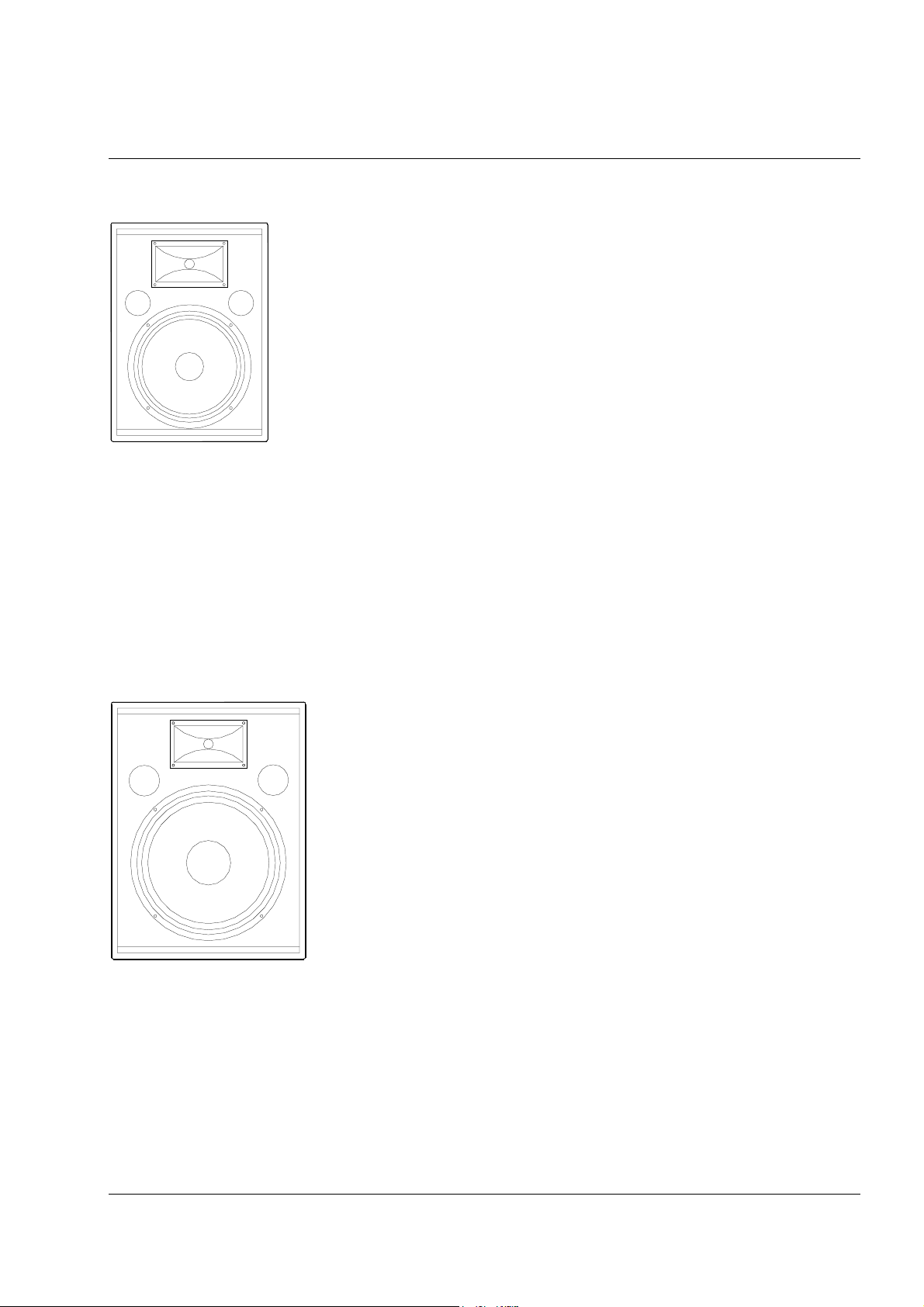
TL-1561
The TL-1561 is a trapezoidal passive three-way loudspeaker
enclosure designed for use in a wide variety of live sound
applications as well as in fixed installations ranging from cafes,
pubs, bars and restaurants to retail stores and houses of
worship.
It consists of a front-loaded 15” low frequency driver, a frontloaded 6.5" mid frequency driver and a 1” high frequency
compression driver on a 70°H x 40°V high frequency horn,
matched with an internal second order passive crossover
network.
The three-way design affords an increase in mid-range energy
when compared to its two-way counterpart, as well as
providing extended low frequency response due to the
increased enclosure size.
A rear panel connector plate carries two Neutrik Speakon NL4MP connectors for loop in / loop out
connections to additional enclosures. Flush handles are provided for easy lifting and carrying.
TL-1500
The TL-1500 is a trapezoidal 15” low frequency enclosure
designed to give low frequency support to TL-1201 or TL-1501
enclosures. As such it can be used in a wide variety of live
sound applications as well as in fixed installations ranging from
cafes, pubs, bars and restaurants to retail stores and houses of
worship.
It consists of a front-loaded 15” low frequency driver and an
internal high pass crossover network in an optimally tuned,
birch plywood enclosure. The cabinet is fitted with a pole mount socket in the top panel.
Two Neutrik Speakon NL4MP connectors provide input and high pass output connections to TL1201 or TL-1501 enclosures. Flush handles are provided for easy lifting and carrying.
TL series manual
page 6
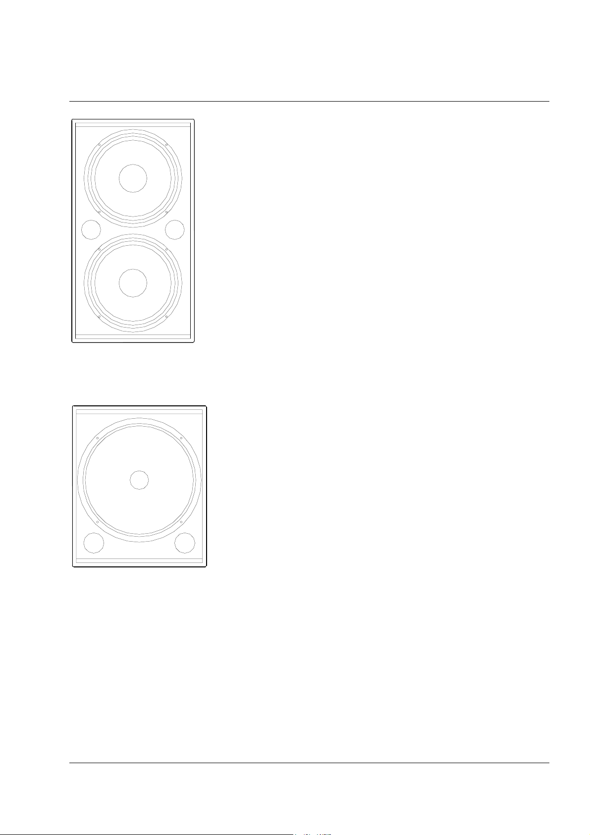
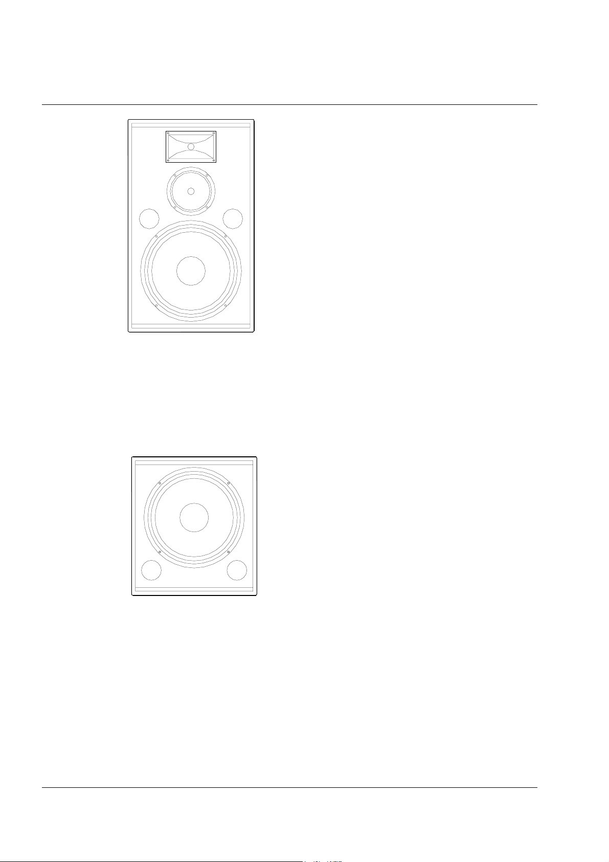
TL-1550
The TL-1550 is a trapezoidal dual 15” low frequency enclosure
designed to give low frequency support to TL-1201 or TL-1501
enclosures. As such it can be used in a wide variety of live
sound applications as well as in fixed installations ranging from
cafes, pubs, bars and restaurants to retail stores and houses of
worship.
It consists of two front-loaded 15” low frequency drivers and an
internal high pass crossover network in an optimally tuned,
birch plywood enclosure. The cabinet is fitted with a pole
mount socket in the top panel.
Two Neutrik Speakon NL4MP connectors provide input and
high pass output connections to TL-1201 or TL-1501 enclosures.
Flush handles are provided for easy lifting and carrying.
user manual
TL series
TL-1800
The TL-1800 is a trapezoidal 18” low frequency enclosure
designed to give low frequency support to TL-1201 or TL1501 enclosures. As such it can be used in a wide variety of
live sound applications as well as in fixed installations
ranging from cafes, pubs, bars and restaurants to retail
stores and houses of worship.
It consists of a front-loaded 18” low frequency driver and
an internal high pass crossover network in an optimally
tuned, birch plywood enclosure. The cabinet is fitted with a
pole mount socket in the top panel.
Two Neutrik Speakon NL4MP connectors provide input and high pass output connections to TL1201 or TL-1501 enclosures. Flush handles are provided for easy lifting and carrying.
TL series manual
page 7

user manual
TL series
SYSTEM REQUIREMENTS
TL series enclosures are passive loudspeaker systems. This means that they require only one
amplifier channel for correct operation, the frequency splitting between the low frequency driver
and the high frequency driver or mid and high frequency driver in two-way and three-way
products being accomplished by the internal passive crossover network built into each enclosure.
If additional low frequency enclosures are used in conjunction with TL series two-way enclosures
to extend low frequency response, no additional amplifier channels or external electronic
crossovers are required. All TL series low frequency enclosures are equipped with internal high
pass crossover networks, splitting the full range signal and feeding the appropriate frequency
band to the two-way enclosure. Therefore a full range system consisting of, for example, a TL1201 and a TL-1500 can be powered from a single amplifier as shown below, thereby saving the
expense of additional amplifiers and external crossovers.
INPUT LINK
TL-1201
TL SERIES
INPUT LINK
AMPLIFIER
TL-1500
TL SERIES
LINKINPUT
INPUT LINK
1. Connect the amplifier output to the Speakon INPUT socket on the bass enclosure.
2. Then connect an additional speaker cable from the LINK socket on the bass cabinet to the
INPUT socket on the full range cabinet. Speakon pin connections are shown below.
TL series manual
page 8
Speakon Pin Wiring
Pin 1+ Positive
Pin 1- Negative
Pin 2+ No Connection
Pin 2- No Connection
1+
2-
1-
2+
Back Front

Amplifier considerations
Turbosound speaker enclosures should be driven by high quality power amplifiers designed for
true professional use. Such amplifiers will have balanced inputs, DC and RF fault protection, and
well-designed cooling systems for reliability. Turbosound power amplifiers such as the TMCT1000 are available and recommended for this purpose.
The program power listed in the loudspeaker’s technical specification is the best guide to the size
of amplifier required for general-purpose applications. The amplifier should therefore be capable
of delivering long term broadband power equal to the loudspeaker’s program power rating at the
loudspeaker’s stated nominal impedance. This approach allows sufficient headroom to generate
good dynamic range.
RECOMMENDED AMPLIFIER POWER RATINGS:
The amplifier's rated r.m.s. continuous power output (20Hz – 20kHz, per
channel) should be equal to the program power handling of the
loudspeaker at its nominal impedance.
user manual
TL series
In general, the more powerful the amplifier the better it will sound, provided that it is not driven
into sustained clipping. It should be understood that overdriving an insufficiently powered
amplifier is more likely to cause loudspeaker damage – the total energy in a heavily clipped signal
is far higher than in an unclipped signal – than operating a more powerful amplifier within its
ratings.
Equalisation
TL series enclosures are designed to provide smooth and even frequency response. They do not
need excessive amounts of external equalisation to overcome the sonic deficiencies often found in
many lesser designs.
In order to compensate for the room acoustics, TL series enclosures require only minimal
equalisation. As in any system, over-equalisation introduces phase shifts, distortion and a
reduction in headroom, usually causing more problems than it cures. Under most circumstances a
1/3 or 1/2 octave graphic equaliser will generally be adequate, with the fader settings applied
smoothly and as little as possible for the required room compensation. Most rooms will have
cut
resonances that will be excited at particular frequencies needing some
These problems are most pronounced at the lower frequencies where loudspeakers generally
exhibit very little directional control. If you find that the system needs a lot of
frequencies you may need additional sub-bass units. It is good practice to use as little equalisation
as possible, aiming to cut frequencies rather than adding large amounts of boost.
to help tame the sound.
boost
at lower
TL series manual
page 9

user manual
TL series
Dispersion
TL series enclosures are designed to provide relatively wide (70°) horizontal coverage. This allows
the majority of live sound applications to be covered with enclosures placed individually to take
advantage of this performance feature, for example either side of a stage in a pub or small club
environment as shown below. The loudspeakers should be either mounted on tripod stands or
supported on straight poles on top of TL-1500, TL-1550 or TL-1800 bass enclosures. In order to
optimise the sound coverage, point the loudspeakers inwards slightly, such that the centre lines
intersect at a distance approximately equal to twice the width of the stage.
STAGE
It is possible to array TL series loudspeakers in order to achieve wider horizontal coverage and in
these applications it is recommended that the cabinets be placed such that the trapezoidal sides
are touching to ensure that the appropriate splay angle is observed. For guidance when designing
a sound system, a 70º horizontal polar pattern equals an angle of 35º either side of the centre line
at which the sound pressure level is 6dB down with respect to centre, (averaged over the whole
frequency range of the loudspeaker). Thus a 40º vertical dispersion gives an angle of 20º above
and below the horizon.
TL series manual
page 10

MOUNTING AND FIXING
Rigging hardware
A versatile range of mounting hardware is available
that allows enclosures to be used in a variety of
ways, in either mobile sound reinforcement
applications or permanent installations.
A pole mount / tripod stand fitting
A pole mount / tripod stand fitting is fitted to the
A pole mount / tripod stand fittingA pole mount / tripod stand fitting
bottom of the TL-1201 and TL-1501 full range
cabinets. Use this pole mount facility with either
optional Turbosound PA-100 35mm diameter poles,
or conventional loudspeaker tripod stands. Doing so
will raise the TL-1201 or TL-1501 loudspeaker above
the heads of an audience, providing better sound
coverage from a single enclosure. A matching pole
mount socket is provided on the top of the TL-1500,
TL-1550 and TL-1800 low frequency enclosures to
accept the PA-100 pole.
user manual
TL series
All TL series cabinets, including low frequency enclosures, can be rigged in permanent
installations using optional M10 shoulder eyebolts
internal threaded rigging points, and a further rigging point is provided on the back panel, below
the connector plate, used to determine the amount of downward angle. As supplied, these rigging
points are fitted externally with M10 countersunk bolts. To facilitate rigging of the enclosure
simply remove these M10 bolts and replace them with M10 x 18mm shoulder eyebolts using a
suitable thread locking compound to avoid the possibility of loosening (please refer to Appendix
C: Use of thread locking compounds at the back of this manual). Note:
thread length of at least 18mm (3/4”).
optional M10 shoulder eyebolts. The top of the cabinet is provided with two
optional M10 shoulder eyeboltsoptional M10 shoulder eyebolts
Note: Eyebolts must have a
Note: Note:
TL series manual
page 11

user manual
TL series
NOTE:
NOTE: The rigging points are designed to suspend single enclosures only. There is no facility to
NOTE: NOTE:
hang an additional cabinet below a flown TL series enclosure.
IMPORTANT:
IMPORTANT: Any installation, whether temporary or permanent, must be securely attached to the
IMPORTANT: IMPORTANT:
structure of the building using chain, steel wires or web straps which are certified and load rated
for the purpose. The combined weight of the sound system, its cables and the rigging system
must be safely carried by the points at which attachment is made to the building or structure.
Great care must be taken in selecting the attachment points and methods, being absolutely sure of
the load carrying capacity of points chosen.
NOTE
NOTE: The rigging of loudspeaker systems is an extremely serious matter with potentially lethal
NOTENOTE
consequences should anything go wrong. It is of vital importance that you, or other people rigging
the system, are suitably qualified to do so and have a full understanding of all the factors involved
with safety as a number one priority. Turbosound accepts no responsibility for any accident,
damage or failure of any rigged system. This rigging information is specifically related to the
requirements of TL series enclosures only. For more detailed information on the whole topic of
rigging various handbooks are available. If you are in any doubt contact your Turbosound dealer
who will be able to refer you to an experienced rigging company.
Choosing the best location
When using any TL series system, certain room parameters will affect the resultant sound quality
and coverage. For example, any boundary like a wall or floor will lift certain frequencies. If you are
placing the unit in a corner then a lift at the bass end is to be expected and it may sound rather
boomy. This can be compensated for moving the speaker or cutting low frequencies with a
graphic equaliser.
When speakers are flown in free space then boundary effects are minimised. The result is a
smooth frequency response without any boost at odd frequencies, but the bass end may appear
subjectively light. In this case increase the sub-bass level to bring the low end up.
The relationship between sound pressure level and distance is an “inverse square law” so
remember that every time the distance from the sound source is doubled the sound level
decreases by 6dB. For every 3dB increase of speaker output you need a doubling of input power
and you can work out the wattage input needed to give the required SPL levels at various
distances from the loudspeaker(s).
TL series manual
page 12

MAINTENANCE
If any of the drive units in your TL series cabinet should cease functioning and need a replacement
recone or diaphragm, you are advised to remove the faulty unit from the cabinet and send it to a
professional service centre authorised to recone and repair Turbosound loudspeakers.
Removal of the low frequency driver(s)
The perforated steel loudspeaker grille is held in place under tension only, fitting into slots at
either side of the baffle. There are no screws or other fixings holding the grille in place.
1. Lay the cabinet on its back and, using two small screwdrivers inserted through the mesh of
the grille, firmly pull the grille away from the slot at one side of the baffle until it is free. Set
the grille aside for later re-assembly.
2. Undo the four screws holding the driver(s) in place and carefully lift it out and away from the
cabinet. Make a note of the driver polarity for later reconnection. Disconnect the cables from
the drive unit and completely remove the driver from the cabinet.
user manual
TL series
3. To reinstate the driver(s) simply reverse the above procedure, making sure you observe the
correct polarity when reconnecting the cables back into the terminals of the drive units.
Removal of the mid frequency driver
1. Remove the loudspeaker grille as described above and set the grille aside for later re-fitting.
2. Undo the four screws holding the driver(s) in place and carefully lift it out and away from the
cabinet. Make a note of the driver polarity for later reconnection. Disconnect the cables from
the drive unit and completely remove the driver from the cabinet. To reinstate the driver
simply reverse the above procedure, making sure you observe the correct polarity when
reconnecting the cables back into the terminals of the drive units.
Removal of the high frequency compression driver
1. Remove the loudspeaker grille as described above and set the grille aside for later re-fitting.
2. Remove the horn/driver assembly by unscrewing the four screws holding the flange in place.
Lift it out and away from the cabinet.
3. The high frequency driver can now be disassembled from the HF horn.
4. To reinstate the high frequency horn and compression driver, simply reverse the above
procedure making sure you observe the correct polarity when reconnecting the cables back
into the terminals of the drive unit.
TL series manual
page 13

user manual
TL series
APPENDIX A
Use of thread locking compounds
When assembling flying hardware to TL series loudspeaker enclosures it is advisable to use
thread-locking compounds to eyebolts and other bolts in order to avoid any possibility of
loosening.
The recommended thread-locking compound is Loctite 222.
The threaded rigging points used in TL series enclosures are manufactured from zinc-plated mild
steel. Therefore, and additionally if the external bolts used are zinc-plated, zinc-passivated,
stainless steel or anodised (as the majority are), then the corresponding activator, Loctite 7471,
should be used to achieve 100% performance.
Application:
Application: Spray Loctite 7471 into the thread holes and allow to evaporate. Apply Loctite 222
Application: Application:
thread locking compound to the bolts prior to fitting, allowing sufficient to fill all the engaged
threads. Assemble components and tighten as necessary.
The parts may be disassembled by hand if required.
TL series manual
page 14

APPENDIX B
Spares and Accessories
CD-106 1” HF compression driver
RD-106 Replacement diaphragm for CD-106
LS-6504 6.5” MF loudspeaker
RC-6504 Recone kit for LS-6504
LS-1211 12” LF loudspeaker
RC-1211 Recone kit for LS-1211
LS-1514 15” LF loudspeaker
RC-1514 Recone kit for LS-1514
LS-1807 18" LF loudspeaker
RC-1807 Recone kit for LS-1807
MG-1201 Metal grille for TL-1201
MG-1501 Metal grille for TL-1501
MG-1561 Metal grille for TL-1561
MG-1500 Metal grille for TL-1500
MG-1550 Metal grille for TL-1550
MG-1800 Metal grille for TL-1800
PX-1201 Passive crossover network for TL-1201
PX-1501 Passive crossover network for TL-1501
PX-1561 Passive crossover network for TL-1561
PX-1500 Passive crossover network for TL-1500
PX-1550 Passive crossover network for TL-1550
PX-1800 Passive crossover network for TL-1800
user manual
TL series
Flying Accessories
EB-10 M10 x 18mm shoulder eyebolt
PA-100 35mm straight pole
TL series manual
page 15

user manual
TL series
APPENDIX C
Technical Specifications
TL-1201
TL-1201 TL-1501
TL-1201TL-1201
TL-1501 TL-1561
TL-1501TL-1501
TL-1561
TL-1561TL-1561
Dimensions
(H x W x D)
Net weight 21kg (46.2lbs) 26kg (57.2lbs) 32kg (70.4lbs)
Components 1 x 12” LF driver
Frequency response 54Hz – 20kHz ±6dB 46Hz – 20kHz ±6dB 42Hz – 20kHz ±6dB
Nominal dispersion 70°H x 40°V @-6dB pts 70°H x 40°V @-6dB pts 70°H x 40°V @-6dB pts
Sensitivity 98dB, 1 watt @ 1metre 99Db, 1 watt @ 1metre 98dB, 1 watt @ 1 metre
Power handling 250 watts r.m.s.
Maximum SPL 122dB continuous
550mm x 395mm x 383mm
(21.6” x 15.5” x 15”)
1 x 1” HF compression driver
500 watts program
128dB peak
635mm x 480mm x 465mm
(25” x 18.9” x 18.3”)
1 x 15” LF driver
1 x 1” HF compression driver
300 watts r.m.s.
600 watts program
124dB continuous
130dB peak
810mm x 480mm x 465mm
(31.9” x 18.9” x 18.3”)
1 x 15” LF driver
1 x 6.5” MF driver
1 x 1” HF compression driver
300 watt r.m.s.
600 watts program
123dB continuous
129dB peak
Construction 15mm (5/8”) birch plywood 15mm (5/8”) birch plywood 15mm (5/8”) birch plywood
Grille Powder coated perforated steel
mesh
Connectors (2) Speakon NL4MP wired
pin 1+ positive,
pin 1- negative
Due to continuing product improvement the above specifications are subject to change.
Powder coated perforated steel
mesh
(2) Speakon NL4MP wired
pin 1+ positive,
pin 1- negative
Powder coated perforated steel
mesh
(2) Speakon NL4MP wired
pin 1+ positive,
pin 1- negative
TL series manual
page 16

TL-1500
TL-1500 TL-1550
TL-1500TL-1500
TL-1550 TL-1800
TL-1550TL-1550
TL-1800
TL-1800TL-1800
user manual
TL series
Dimensions
(H x W x D)
Net weight 23kg (50.6lbs) 37kg (81.4lbs) 26kg (57.2lbs)
Components 1 x 15” LF driver 2 x 15” LF drivers 1 x 18” LF driver
Frequency response 50Hz – 225Hz ±6dB 50Hz – 225Hz ±6dB 42Hz – 225Hz ±6dB
Sensitivity 99dB, 1 watt @ 1metre 101dB, 1 watt @ 1metre 97dB, 1 watt @ 1 metre
Power handling 300 watts r.m.s.
Maximum SPL 122dB continuous
Construction 15mm (5/8”) birch plywood 15mm (5/8”) birch plywood 15mm (5/8”) birch plywood
Grille Powder coated perforated steel
530mm x 480mm x 465mm
(20.9” x 18.9” x 18.3”)
600 watts program
128dB peak
mesh
875mm x 480mm x 465mm
(34.4” x 18.9” x 18.3”)
600 watts r.m.s.
1200 watts program
124dB continuous
130dB peak
Powder coated perforated steel
mesh
600mm x 500mm x 485mm
(23.6” x 19.7” x 19”)
350 watt r.m.s.
700 watts program
123dB continuous
129dB peak
Powder coated perforated steel
mesh
Connectors (2) Speakon NL4MP wired
pin 1+ positive,
pin 1- negative
(2) Speakon NL4MP wired
pin 1+ positive,
pin 1- negative
Due to continuing product improvement the above specifications are subject to change.
(2) Speakon NL4MP wired
pin 1+ positive,
pin 1- negative
TL series manual
page 17

user manual
TL series
APPENDIX D
Limited Warranty
This Turbosound loudspeaker product is warranted to the original end-user purchaser and all
subsequent owners for a period of two (2) years from the original date of purchase.
Warranty Coverage
Warranty Coverage
Warranty CoverageWarranty Coverage
Warranty coverage includes defects in materials and workmanship. It does not include:
•
damage caused by accident, misuse, abuse, neglect or modification by any person other than
an authorised Turbosound representative,
•
damage caused by failure to operate the product in accordance with the instructions
contained in the user manual,
•
damage occurring during shipment in transit,
•
claims based on any misrepresentation by the seller,
•
products which do not have the original components as specified in the product engineering
information,
•
products on which the serial number has been removed or defaced.
Shipping
Shipping
ShippingShipping
Should any fault develop with a component of your Turbosound system, please return the
product, freight pre-paid, in its original packing carton, along with proof of purchase such as the
original bill of sale or receipted invoice, and a description of the suspected fault to Turbosound
Ltd. (Att: Customer Service), Star Road, Partridge Green, West Sussex RH13 8RY, England, or your
local authorised Turbosound representative. The product serial number must be quoted in all
correspondence relating to the claim. Insurance is recommended, as Turbosound or its
representatives are not liable for loss or damage in transit. Turbosound will pay for return freight
costs should repairs be covered under warranty.
TL series manual
page 18

Incidental and consequential damages
Incidental and consequential damages
Incidental and consequential damagesIncidental and consequential damages
Turbosound's liability is limited to the repair or replacement, at our option, of any defective
product, and shall not be liable for any incidental and consequential damages including, without
limitation, injury to persons or property or loss of use.
Limitation of implied warranties
Limitation of implied warranties
Limitation of implied warrantiesLimitation of implied warranties
All implied warranties, including warranties of merchantability and fitness for a particular
purpose, are limited in duration to the length of this warranty.
This warranty is in addition to, and in no way detracts from, your statutory rights as a consumer.
No other warranty is expressed or implied.
Please record your purchase information below for future reference:
Dealer Name _______________________________________________________________________
Dealer Address ____________________________________________________________________
user manual
TL series
___________________________________________________________________________________
___________________________________________________________________________________
Post / Zip Code _____________________________________________________________________
Dealer telephone / fax ______________________________________________________________
Invoice number ____________________________________________________________________
Date of purchase ___________________________________________________________________
Unit serial number _________________________________________________________________
TL series manual
page 19

Turbosound Ltd.
Star Road, Partridge Green
West Sussex RH13 8RY England
Tel: +44 (0)1403 711447 Fax: +44 (0)1403 710155
web: www.turbosound.com
 Loading...