

Page 1

user manual
Flashline
TFS-900 Flashline Loudspeaker System
User Manual
Flashline User Manual
page 1
Page 2

user manual
Flashline
CONTENTS
1. IMPORTANT SAFETY INSTRUCTIONS (AMPLIFIERS) .................................................................................................................... 4
1.1 Safety Instructions for 20000DP ................................................................................................................................................. 4
1.2 Standards ..................................................................................................................................................................................... 4
1.3 Explanation of Graphical Symbols ............................................................................................................................................ 5
1.4 Warning ........................................................................................................................................................................................ 5
1.5 Caution .........................................................................................................................................................................................5
1.6 FCC Compliance Notice (Radio Interference) ...........................................................................................................................5
1.7 User Responsibility .....................................................................................................................................................................6
2. WELCOME ..........................................................................................................................................................................................7
2.1 Introduction ................................................................................................................................................................................. 7
2.2 Thanks ..........................................................................................................................................................................................7
2.3 Unpacking ....................................................................................................................................................................................7
3. THE FLASHLINE SYSTEM .................................................................................................................................................................8
3.1 TFS-900H mid/high loudspeaker ................................................................................................................................................ 8
3.2 TFS-900B Subwoofer and TFS-900L Subwoofer ...................................................................................................................... 9
3.3 TFS-DOLLY and TFS-COVER ....................................................................................................................................................11
3.4 TFS-RACK ..................................................................................................................................................................................12
4. CONNECTING THE LOUDSPEAKERS ............................................................................................................................................14
4.1 Wiring convention ..................................................................................................................................................................... 14
4.2 Damping Factor in cable ........................................................................................................................................................... 14
4.3 Power Output Performance ...................................................................................................................................................... 14
5. SYSTEM CONFIGURATIONS .......................................................................................................................................................... 15
5.1 Suggested amplifier loading for the TFS-900H ...................................................................................................................... 15
5.2 Suggested amplifier loading for subwoofers ......................................................................................................................... 16
5.3 Suggested amplifier loading for subwoofers in cardioid mode ...........................................................................................17
5.4 Suggested amplifier loading for a 4-way Flex Array system ................................................................................................ 18
6. AMPLIFIER RACK ROUTING ........................................................................................................................................................... 19
6.1 TFS-RACK High output routing ................................................................................................................................................19
6.2 TFS-RACK Low output routing ................................................................................................................................................. 19
6.3 TFS-RACK Flex Array routing, TFA-600L/B ............................................................................................................................. 20
6.4 TFS-RACK Flex Array routing TSW-218 .................................................................................................................................. 20
7. RIGGING THE FLASHLINE SYSTEM ..............................................................................................................................................21
7.1 Overview ....................................................................................................................................................................................21
7.2 TFS-FT900 Fly Trunk ..................................................................................................................................................................21
7.3 Flying an Array ..........................................................................................................................................................................22
7.4 De-rigging the Array ................................................................................................................................................................. 29
7.5 Flex Array as Downfills ............................................................................................................................................................. 30
8. THE 20000DP AMPLIFIER ................................................................................................................................................................ 31
8.1 Main features ............................................................................................................................................................................. 31
8.2 Additional Documentation ....................................................................................................................................................... 32
9. AMPLIFIER INSTALLATION ............................................................................................................................................................. 33
Flashline User Manual
page 2
Page 3

user manual
Flashline
9.1 Unpacking ................................................................................................................................................................................33
9.2 Mounting .................................................................................................................................................................................33
9.3 Rear Mounting .........................................................................................................................................................................33
9.4 Cooling .....................................................................................................................................................................................35
9.5 Operating Voltage ...................................................................................................................................................................35
9.6 Grounding ................................................................................................................................................................................36
10. PRODUCT OVERVIEW .................................................................................................................................................................36
10.1 Front Panel Overview ...........................................................................................................................................................36
10.2 Back Panel Overview ............................................................................................................................................................38
11. SIGNAL FLOW AND LAKE PROCESSING ..................................................................................................................................41
11.1 Signal Flow ............................................................................................................................................................................41
11.2 Level Adjustments & Mute Points .......................................................................................................................................41
11.3 Power Output Section: Limiting and Sensitivity ................................................................................................................42
11.4 Lake Processing and Control ................................................................................................................................................43
11.5 Modules and Frames ............................................................................................................................................................43
11.6 LoadLibrary™ and Fingerprints ...........................................................................................................................................43
11.7 Super Modules ......................................................................................................................................................................44
11.8 Loudspeaker Crossover Configuration Overview ..............................................................................................................44
11.9 Files and Presets ...................................................................................................................................................................44
12. LAKE CONTROLLER SOFTWARE ...............................................................................................................................................46
12.1 Introduction ...........................................................................................................................................................................46
12.2 Lake Processing and Control ................................................................................................................................................46
12.3 Installing the Lake Controller Software ...............................................................................................................................46
12.4 Gain Structure .......................................................................................................................................................................47
12.5 Gain / Level Optimization .....................................................................................................................................................48
13. WARRANTY AND SUPPORT .......................................................................................................................................................49
13.1 General ...................................................................................................................................................................................49
13.2 International Warranties .......................................................................................................................................................49
13.3 Technical Assistance and Service ........................................................................................................................................49
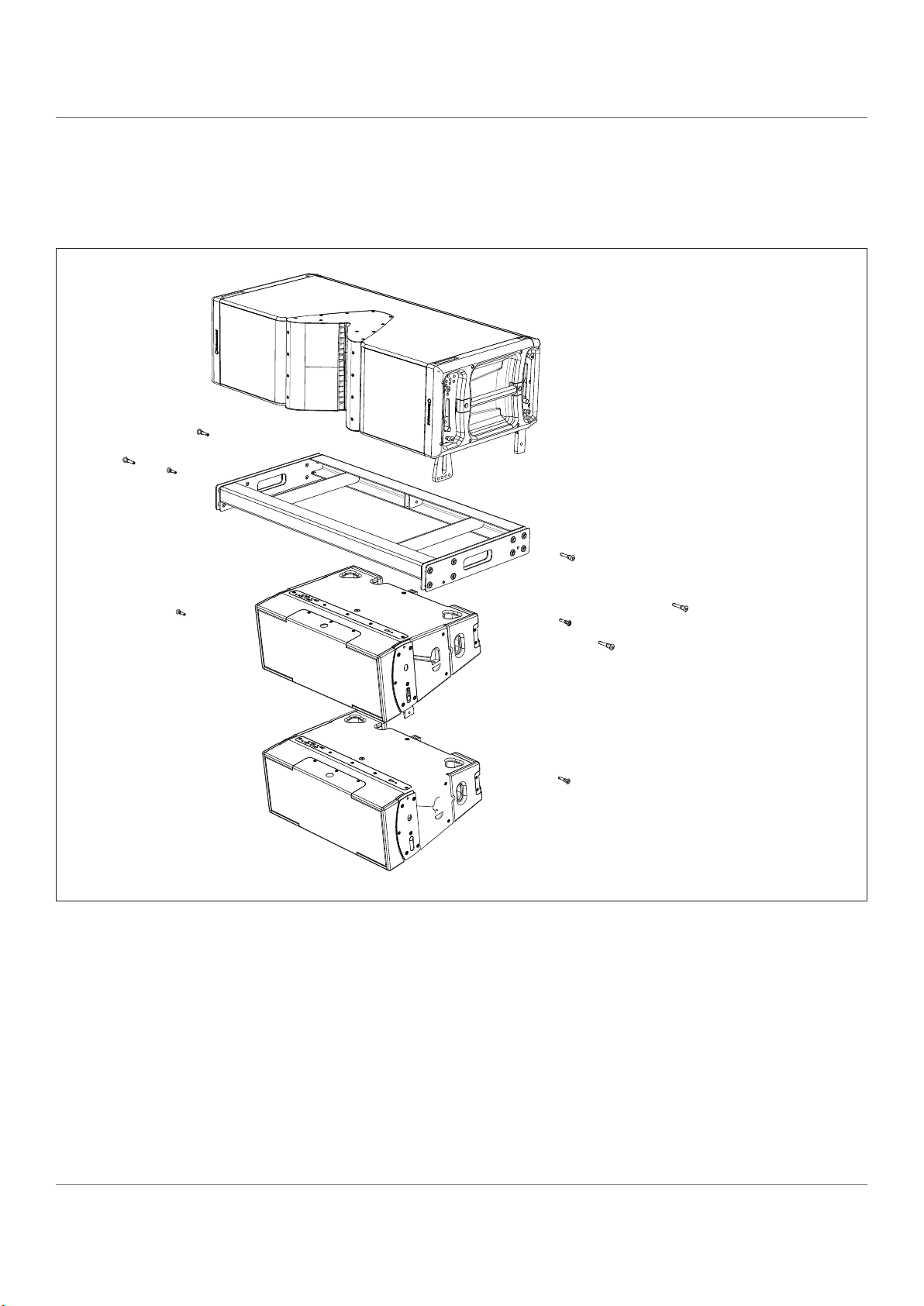
14. MAINTENANCE ............................................................................................................................................................................50
14.1 Removal of the drive units ...................................................................................................................................................50
15. TECHNICAL SPECIFICATIONS ....................................................................................................................................................51
Flashline User Manual
page 3
Page 4

user manual
Flashline
1. Important Safety Instructions (Amplifiers)
Before using the device, be sure to carefully read the Safety Instructions. Keep this document with the
device at all times.
1.1 Safety Instructions for 20000DP
• Read these instructions.
• Keep these instructions.
• Heed all warnings.
• Follow all instructions.
• Do not use this apparatus near water.
• Clean only with a dry cloth.
• Do not block any ventilation openings. Install in accordance
with the manufacturer’s instructions.
• Do not install near any heat sources such as radiators, heat
registers, stoves, or other apparatus (including amplifiers) that
produce heat.
• Do not defeat the safety purpose of the polarized or groundingtype plug. A polarized plug has two blades with one wider than
the other. A grounding-type plug has two blades and a third
grounding prong. The wide blade or the third prong is provided
for your safety. If the provided plug does not fit into your outlet,
consult an electrician for replacement of the obsolete outlet.
• Protect the power cord from being walked on or pinched,
particularly at plugs, convenience receptacles, and the point
where they exit from the apparatus.
• Only use attachments/accessories specified by the
manufacturer.
• Unplug this apparatus during lightning storms or when unused
for long periods of time.
• Refer all servicing to qualified service personnel. Servicing is
required when the apparatus has been damaged in any way,
such as power-supply cord or plug is damaged, liquid has been
spilled or objects have fallen into the apparatus, the apparatus
has been exposed to rain or moisture, does not operate
normally, or has been dropped.
• Use the mains plug to disconnect the apparatus from the mains.
• WARNING: To reduce the risk of fire of electric shock, do not
expose this apparatus to rain or moisture.
• Do not expose this equipment to dripping or splashing and
ensure that no objects filled with liquids, such as vases, are
placed on the equipment.
• The mains plug of the power supply cord shall remain readily
operable.
• Do not connect the unit’s output to any other voltage source,
such as battery, mains source, or power supply, regardless of
whether the unit is turned on or off.
• Do not remove the top (or bottom) cover. Removal of the cover
will expose hazardous voltages. There are no user serviceable
parts inside and removal may void the warranty.
• An experienced user shall always supervise this professional
audio equipment, especially if inexperienced adults or minors
are using the equipment.
• The US National Differences clause 16.3 requires that network
cables must be flame rated VW-1.
• To prevent electric shock do not remove top or bottom covers.
No user serviceable parts inside, refer servicing to
qualified service personnel.
• à prévenir le choc électrique n’enlevez pas les couvercles.
Il n’y a pas des parties serviceable à l’intérieur, tous
reparations doit etre faire par personnel qualifié
seulment.
• To completely disconnect this equipment from the AC mains,
disconnect the power supply cord plug from the AC
receptacle. The mains plug of the power supply cord
shall remain readily operable.
• Pour démonter complètement l’équipement de l’alimentation
générale, démonter le câble d’alimentation de son
réceptacle. La prise d’alimentation restera aisément
fonctionnelle.
1.2 Standards
This equipment conforms to the
requirements of the EMC Directive 2004/108/
EC and the requirements of the Low Voltage
Directive 2006/95/EC. Standards applied:
EMC Emission, EN55103-1, E3, EMC Immunity EN551032, E3, with S/N below 1% at normal operation level.
Electrical Safety EN60065, Class I
This equipment is tested and listed according
to the U.S. safety standard ANSI/ UL 60065
and Canadian safety standard CSA C22.2 NO.
60065. Intertek made the tests and they are a Nationally
Recognized Testing Laboratory (NRTL).
Flashline User Manual
page 4
Page 5

user manual
Flashline
1.3 Explanation of Graphical Symbols
The lightning bolt triangle is used to alert the user to the presence of un-insulated “dangerous voltages”
within the unit’s chassis that may be of sufficient magnitude to constitute a risk of electric shock to humans.
The exclamation point triangle is used to alert the user to presence of important operating and service
instructions in the literature accompanying the product.
1.4 Warning
To reduce risk of fire or electric shock, do not expose this apparatus to rain or moisture.
Pour réduire les risques de blessure ou le choc électrique, n’exposez pas l’appareil à la pluie ou à l’humidité.
Do not expose this system/apparatus to dripping or splashing and ensure that no objects filled with liquids, such as
vases, are placed on the apparatus.
L’appareil ne doit pas être exposé à des egouttements d’eau ou des éclaboussures et de plus qu’aucun objet rempli
de liquide tel que des vases ne doit pas être placé sur l’appareil.
This apparatus must be connected to a mains socket outlet with a protective earthing connection.
Cet appareil doit être raccordé á une prise de courant qui est branchée à la terre.
The mains plug is used as a disconnect device and shall remain readily operable.
Lorsque la prise du réseau d’alimentation est utilisés comme dispositif de déconnexion, ce dispositif doit
demeuré aisément accessible.
1.5 Caution
To reduce the risk of fire or electric shock, do not remove screws. No user-serviceable parts inside.
Refer servicing to qualified service personnel.
Pour réduire le risque d’incendie ou de choc électrique, ne pas retirer les vis. Aucune pièce réparable par l’utilisateur.
Confier l’entretien àpersonnel qualifié.
1.6 FCC Compliance Notice (Radio Interference)
A sample of this product has been tested and complies with the limits for the European Electro Magnetic
Compatibility (EMC) directive. This equipment has also been tested and found to comply with the limits for a Class
B digital device, pursuant to Part 15 of the FCC Rules. These limits are designed to provide reasonable protection
against harmful interference from electrical equipment. This product uses radio frequency energy and if not used or
installed in accordance with these operating instructions, may cause interference to other equipment, such as radio
receivers.
However, there is no guarantee that interference will not occur in a particular installation. If this equipment does
cause harmful interference to radio or television reception, which can be determined by turning the equipment on
and off, the user is encouraged to try to correct the interference by one or more of the following measures:
• Re-orient or relocate the antenna.
• Increase the separation between the equipment and receiver.
• Connect the equipment to an outlet on a circuit different from that to which the receiver is connected.
Flashline User Manual
page 5
Page 6

user manual
Flashline
• Check if the affected unit complies with the EMC limits for immunity, (CE-labeled). If not, address the problem
with the manufacturer or supplier. All electrical products sold in the EC must be approved for immunity against
electromagnetic fields, high voltage flashes, and radio interference.
• Consult the dealer or an experienced radio/TV technician for help.
1.7 User Responsibility
1.7.1 Mains Connection Grounding
Your apparatus must be connected to a grounded socket outlet.
1.7.2 Speaker Output Hazard on Amplifiers
Amplifiers are capable of producing hazardous output voltages. To avoid electrical shock, do not touch any exposed
speaker wiring while the amplifier is operating. The external wiring connected to the speaker terminals shall be
installed by a qualified person, or ready-made leads or cords of appropriate capacity shall be used.
As the power output channels on amplifiers produce high voltage, do not connect or disconnect speaker cables
when the mains power is on.
1.7.3 Speaker Damage
Amplifier apparatus is very powerful and can be potentially dangerous to both loudspeakers and humans
alike. Many loudspeakers can be easily damaged or destroyed by overpowering them. Always check the
speaker’s continuous and peak power capabilities. Although the amplifiers attenuators can be used to reduce the
overall gain, an increase of the input signal can result in full output power, which may cause damage to connected
speakers.
1.7.4 Maintenance
For safe and reliable operation, the dust filter on should be removed and cleaned regularly to ensure maximum
airflow through the device. If the dust filters are not maintained there will be safety risks; for example, high internal
temperatures could ignite the dust and start a fire. There is also a risk that the unit will malfunction since it is
dependent on constant airflow from front to rear.
If the dust filters are not clean and the unit malfunctions, any resulting problems will not be covered by the
warranty.
Flashline User Manual
page 6
Page 7

user manual
Flashline
2. Welcome
2.1 Introduction
Congratulations, you have purchased a professional loudspeaker product from the Flashline series of products. If
you would like further information about this or any other TURBOSOUND product, please contact us on +44 (0)1403
711447.
Always check the Turbosound website for the latest updates on the technical documentation relating to this product
at www.turbosound.com
2.2 Thanks
Thank you for choosing a TURBOSOUND product for your application. By engaging in an ongoing rigorous process
of research and development all TURBOSOUND products are carefully engineered for world class performance and
reliability.
2.3 Unpacking
After unpacking the unit please check carefully for damage. If damage is found, please notify your supplier at once.
You, the consignee, must instigate any claim. Please retain all packaging in case of future re-shipment.
Flashline User Manual
page 7
Page 8

user manual
TFS-900H Butterfly plate
Flashline
3. The Flashline System
The Flashline TFS-900 System is a complete, fully integrated, large scale, five-way two-box line array sound
reinforcement system. It comprises mid/high and sub-bass loudspeakers, amplification and system control racks,
flying hardware, and transport cases in a very powerful and space-efficient format.
The Flashline system is designed to allow integration of systems around the world with guaranteed ‘out of the box’
compatibility.
3.1 TFS-900H mid/high loudspeaker
The TFS-900H is a four-way line array module covering the frequency range above 70Hz and containing three 1”
high frequency compression drivers loaded by Dendritic waveguides, two 6.5” high-mid cone transducers loaded by
Polyhorns, four 6.5” horn-loaded low-mid cone transducers, and two 12” horn-loaded low frequency transducers.
The rigging hardware is integrated into the end-cheeks on each side of the TFS-900H cabinet, which also provide
grab handle positions. Drop links at the front and rear of the box engage in the flygear of the box below it in the
array to give a range of inter-cabinet angles from 0° to 5°. TFS-900H cabinets are normally transported four-up
on the TFS-DOLLY and can be flown right off the dolly in blocks of four, with the rigging hardware already preconfigured for use. A simple TFS-GRID and TFS-TIP system is used to fly a typical array; no additional external parts
are required to fly the system.
The cabinet is finished in black TourTough finish.
TFS-900H Horn
TFS-900H Grilles
TFS-900H Endcheek
TFS-900H Flying pins
TFS-900H Handle
TFS-900H Flying pins
Flashline User Manual
page 8
TFS-900H Rear Drop link
TFS-900H Front Drop link
Page 9

TFS-900H Rear Droplink
TFS-900H NL8 Connectors
user manual
Flashline
TFS-900H Rear Doors
3.2 TFS-900B Subwoofer and TFS-900L Subwoofer
The TFS-900B is a dual 18” subwoofer employing hybrid loading techniques using the advantages of both bass
reflex loading and horn loading to develop extremely high levels of bass and sub-bass energy.
The TFS-900B is designed for ground stacking in support of TFS-900H cabinets and includes stacking feet and
matching cabinet recesses to ensure stability. Heavy duty wheels are fitted for transportation.
The TFS-900L includes rigging hardware to allow it be flown in standard and cardioid configuration and it is
equipped with heavy duty wheels for transportation.
The TFS-900B and TFS-900L are both fitted with a pair of NL4 connectors. The drivers are wired independently in
order to benefit from the maximum power transfer from the 20000DP amplifiers. Both cabinets are finished in black
TourTough as standard.
TFS-900H Front Droplink
Flashline User Manual
page 9
Page 10

user manual
Flashline
TFS-900B driver access door
TFS-900B
stacking foot
TFS-900B driver
access door
TFS-900B stacking foot
TFS-900B NL4 connectors
Flashline User Manual
page 10
Page 11

user manual
Flashline
3.3 TFS-DOLLY and TFS-COVER
The TFS-DOLLY allows cabinets to be transported and loaded directly from truck to stage area in a venue in blocks of
four. The total weight of the stack and dolly including cover is 465.5kg.
The heavy duty TFS-COVER is designed to protect the cabinets during transit. The front and rear flaps are secured
with velcro and allow the fronts of the cabinets to be accessible.
Note that when transporting Flashline cabinets on
the TFS-DOLLY that four people are required for
handling the dolly in and out of trucks and stage
loading area.
Flashline User Manual
page 11
Page 12

user manual
Flashline
3.4 TFS-RACK
The TFS-Rack contains three 20000DP amplifiers configured to drive each of the four frequency bands in the TFS900H from its four output channels, or to drive subwoofers.
2 3
1
5
4
6
7
3.4.1 TFS-RACK panel connectors
1. A 19-pin female C mil connector provides multi-way signal connections to the rack. Mil C 5015 & VG 95234. The
mil-spec insert Number is 22-14
2. A 19-pin male C mil connector links out to additional racks
3. AES/EBU One male and one female connector, looped through
4. Ethernet and Dante connectors, looped through
5. Mains power to the rack is provided by a 32A three phase distro on a C-Form (EMEA) or Twist-Lock (USA)
connector.
6. Speaker outputs for the TFS-900H high packs are on three NL8 connectors, one per amplifier
7. Subwoofer outputs are on six NL4 connectors, two per amplifier.
Flashline User Manual
page 12
Page 13

3.4.2 Cable pin-outs
4+ High positive (+ve)
2 - Sub driver 2 negative (-ve)
The NL8 connectors are wired as follows:
4+
4-
1-
4
- High negative (-ve)
user manual
Flashline
1+
2-
2+
The NL4 connectors are wired as follows:
2+
1+
2-
3+
3-
3+ Mid positive (+ve)
3
- Mid negative (-ve)
2 - Low positive (+ve)
2 - Low negative (-ve)
1
- Bass positive (+ve)
1 - Bass negative (-ve)
2 + Sub driver 2 positive (+ve)
1-
1 - Sub driver 1 negative (-ve)
+ Sub driver 1 positive (+ve)
1
Flashline User Manual
page 13
Page 14

user manual
Flashline
4. Connecting the Loudspeakers
4.1 Wiring convention
CONFIGURED FOR TFS-900H CONFIGURED FOR 4-WAYCONFIGURED FOR TFS-900B/L
4.2 Damping Factor in cable
Turbosound recommends that for large scale PA use the total system damping factor should be 15 or greater. Longer
cables will reduce the overall damping factor of the system. In order to keep the damping factor over 15 it will be
necessary to increase the impedance of the load to keep the damping factor. Therefore for long runs Turbosound
recommends no more than two enclosures per amplifier. Turbosound recommends using 4mm2 cable as standard.
Cable size
2
mm
2.5 38 125 18 59 12 39
4 60 197 30 98 20 66
6 90 295 45 148 30 98
Length for 1 x TFS-900H (8 ohms)
m ft
Length for 2 x TFS-900H (4 ohms)
m ft
Length for 3 x TFS-900H (2.6 ohms)
m ft
4.3 Power Output Performance
Symmetrical Power
The 20000DP can deliver power as shown in the table below when all channels are driven equally.
Load Impedance (ohms) 2.0 2.7 4 8 16
20000DP Max power output (watts) 4800 5000 4440 2300 1150
Asymmetrical Power
Load Impedance (ohms) 2.0 2.7 4 8 16
20000DP Max power output (watts) 5000 5000 4500 2300 1150
Flashline User Manual
page 14
Page 15

5. System Configurations
5.1 Suggested amplifier loading for the TFS-900H
user manual
Flashline
Each amplifier powers three enclosures. Whilst in theory the amplifier can power four enclosures this presents the
bass and low-mid with a 2 ohm load, which does not offer optimum performance.
BASS loading 2.6 ohms
LOW loading 2.6 ohms
MID loading 4 ohms
HIGH loading 6 ohms
Each amplifier is connected to one of the three
phases on the power supply. For optimum loading on
large systems it is good practice to load all phases
equally.
Flashline User Manual
page 15
Page 16
user manual
Flashline
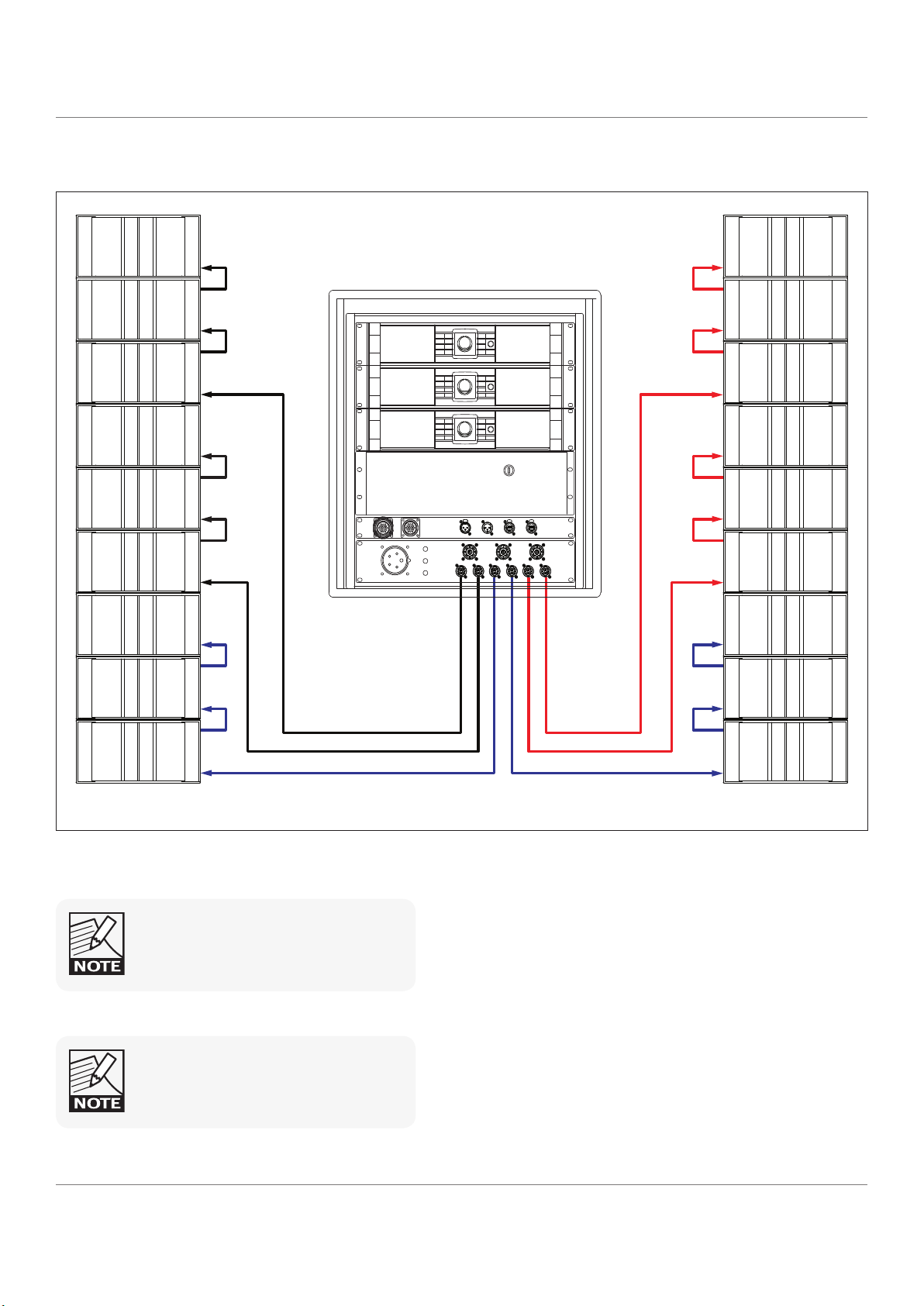
5.2 Suggested amplifier loading for subwoofers
Each amplifier powers up to six TFS-900B or TFS-900L enclosures. Each NL4 connector can power three
subwoofers. Each subwoofer has a drive unit wired to each pair of pins on the NL4 connectors.
Do not use the NL4 and NL8 connections
simultaneously on one amplifier.
In this configuration speaker cable lengths should not be greater than 20m due to damping factor considerations.
Each amplifier is connected to one of the three
phases on the power supply. For optimum loading on
large systems it is good practice to load all phases
equally.
Flashline User Manual
page 16
Page 17

Flashline
5.3 Suggested amplifier loading for subwoofers in cardioid mode
user manual
Each amplifier powers four TFS-900L or TFS-900B enclosures. The first NL4 on each amplifier powers the rear facing
cardioid unit, while the second NL4 powers the three forward facing units.
In this configuration speaker cable lengths should not be greater than 20m due to damping factor considerations.
Do not use the NL4 and NL8 connections
simultaneously on one amplifier.
Do not use the NL4 and NL8 connections
simultaneously on one amplifier.
Flashline User Manual
page 17
Page 18
user manual
Flashline
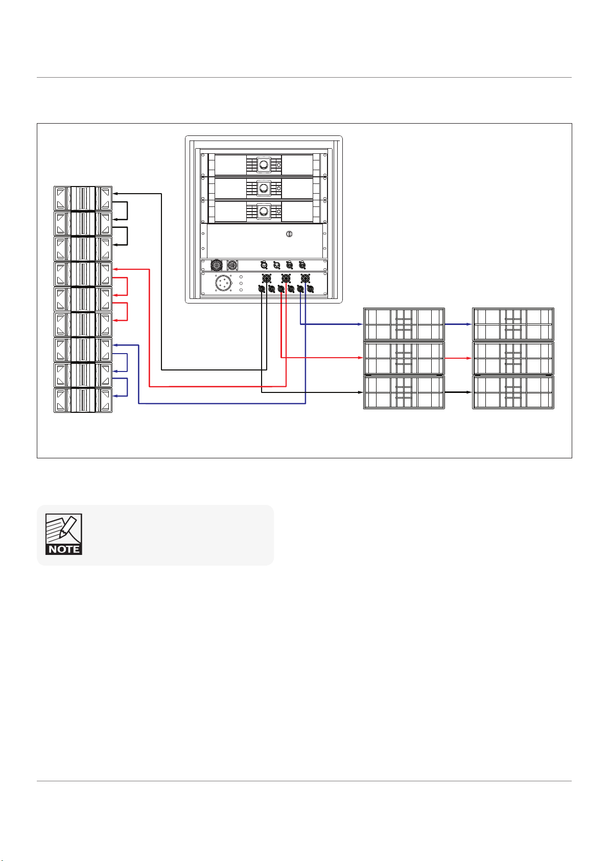
5.4 Suggested amplifier loading for a 4-way Flex Array system
Each amplifier powers three Flex Array TFA-600H cabinets and two TSW-218 subwoofers. In this instance the NL4 and
NL8 connections can be used simultaneously since the amplifier presets configure the outputs correctly.
Do not use the NL4 and NL8 connections
simultaneously on one amplifier.
Flashline User Manual
page 18
Page 19

Flashline
6. AMPLIFIER RACK ROUTING
6.1 TFS-RACK High output routing
AMP CHANNEL MAX NO OF ENCLOSURES CABINET DUTY NL8 NL8 PIN
20000DP - 1 CH1
20000DP - 1 CH2 TFS-900H 6.5” low 1 2+/2-
20000DP - 1 CH3 TFS-900H 6.5” mid 1 3+/3-
20000DP - 1 CH4 TFS-900H 1” high 1 4+/4-
20000DP - 2 CH1
20000DP - 2 CH2 TFS-900H 6.5” low 2 2+/2-
20000DP - 2 CH3 TFS-900H 6.5” mid 2 3+/3-
20000DP - 2 CH4 TFS-900H 1” high 2 4+/4-
20000DP - 3 CH1
20000DP - 3 CH2 TFS-900H 6.5” low 3 2+/2-
20000DP - 3 CH3 TFS-900H 6.5” mid 3 3+/3-
20000DP - 3 CH4 TFS-900H 1” high 3 4+/4-
3
3
3
TFS-900H 12” bass 1 1+/1-
TFS-900H 12” bass 2 1+/1-
TFS-900H 12” bass 3 1+/1-
user manual
6.2 TFS-RACK Low output routing
AMP CHANNEL MAX NO OF ENCLOSURES CABINET DUTY NL8 NL8 PIN
20000DP - 1 CH1
20000DP - 1 CH2 TFS-900L/B 18” driver 2 1 2+/2-
20000DP - 1 CH3 TFS-900L/B 18” driver 1 2 1+/1-
20000DP - 1 CH4 TFS-900L/B 18” driver 2 2 2+/2-
20000DP - 2 CH1
20000DP - 2 CH2 TFS-900L/B 18” driver 2 3 2+/2-
20000DP - 2 CH3 TFS-900L/B 18” driver 1 4 1+/1-
20000DP - 2 CH4 TFS-900L/B 18” driver 2 4 2+/2-
20000DP - 3 CH1
20000DP - 3 CH2 TFS-900L/B 18” driver 2 5 2+/2-
20000DP - 3 CH3 TFS-900L/B 18” driver 1 6 1+/1-
20000DP - 3 CH4 TFS-900L/B 18” driver 2 6 2+/2-
3
3
3
TFS-900L/B 18” driver 1 1 1+/1-
TFS-900L/B 18” driver 1 3 1+/1-
TFS-900L/B 18” driver 1 5 1+/1-
Flashline User Manual
page 19
Page 20

user manual
Flashline
6.3 TFS-RACK Flex Array routing, TFA-600L/B
AMP CHANNEL MAX NO OF ENCLOSURES CABINET DUTY NL8 NL8 NL4 NL4
20000DP - 1 CH1 3 TFA-600L/B 18” Sub 1 1+/1-
20000DP - 1 CH2
20000DP - 1 CH3 TFA-600H/HW 6.5” Himid 1 3+/3-
20000DP - 1 CH4 TFA-600H/HW 1” High 1 4+/4-
20000DP - 2 CH1 3 TFA-600L/B 18” Sub 3 1+/1-
20000DP - 2 CH2 TFA-600H/HW 10” Lomid 2 2+/2-
20000DP - 2 CH3 3 TFA-600H/HW 6.5” Himid 2 3+/3-
20000DP - 2 CH4 TFA-600H/HW 1” High 2 4+/4-
20000DP - 3 CH1 3 TFA-600L/B 18” Sub 5 1+/1-
20000DP - 3 CH2
20000DP - 3 CH3 TFA-600H/HW 6.5” Himid 3 3+/3-
20000DP - 3 CH4 TFA-600H/HW 1” High 3 4+/4-
3
3
TFA-600H/HW 10” Lomid 1 2+/2-
TFA-600H/HW 10” Lomid 3 2+/2-
6.4 TFS-RACK Flex Array routing TSW-218
AMP CHANNEL MAX NO OF ENCLOSURES CABINET DUTY NL8 NL8 NL4 NL4
20000DP - 1 CH1 1 TSW-218 18” Sub 1 1+/1-
20000DP - 1 CH2
20000DP - 1 CH3 TFA-600H/HW 6.5” Himid 1 3+/3-
20000DP - 1 CH4 TFA-600H/HW 1” High 1 4+/4-
20000DP - 2 CH1 1 TSW-218 18” Sub 3 1+/1-
20000DP - 2 CH2
20000DP - 2 CH3 TFA-600H/HW 6.5” Himid 2 3+/3-
20000DP - 2 CH4 TFA-600H/HW 1” High 2 4+/4-
20000DP - 3 CH1 1 TSW-218 18” Sub 5 1+/1-
20000DP - 3 CH2
20000DP - 3 CH3 TFA-600H/HW 6.5” Himid 3 3+/3-
20000DP - 3 CH4 TFA-600H/HW 1” High 3 4+/4-
3
3
3
TFA-600H/HW 10” Lomid 1 2+/2-
TFA-600H/HW 10” Lomid 2 2+/2-
TFA-600H/HW 10” Lomid 3 2+/2-
Flashline User Manual
page 20
Page 21

user manual
Flashline
7. Rigging the Flashline system
7.1 Overview
The rigging system consists of the following main components:
• TFS-GRID – a rectangular box section flying frame that supports a column of up to 20 cabinets
• TFS-TIP – a central bar which provides front and rear pick up points
• TFS-FT900 – the fly trunk houses two TFS-GRID flybars and associated parts such as shackles and locking bolts. It
is designed so as to allow the flybar to be connected and lifted out of the case with minimal manual handling
• Flex Array cabinets can be flown underneath as downfills using the CF-900 conversion frame
• RECLINE laser pointer allows remote monitoring of the vertical inclination of the array
7.2 TFS-FT900 Fly Trunk
TFS-FT900 Fly trunk lid
TFS-TIP tipper bar
TFS-GRID
TFS-FT900 Fly trunk
TFS-FT900 Fly trunk lid
Flashline User Manual
page 21
Page 22

user manual
Flashline
7.3 Flying an Array
• A single TFS-FT900 fly trunk contains two complete flybar assemblies and associated parts. Position the TFS-
FT900 fly trunk directly under the motors and tip it onto one side.
• Unlatch and remove the TFS-FT900 fly trunk lid to gain access to the TFS-GRID flybar, TFS-TIP tipper bar, and the
shackles and tipper bar retaining bolts stowed inside.
Flashline User Manual
page 22
Page 23

user manual
1 2 3
FRONT
CLUSTER POINTS UP CLUSTER LEVEL CLUSTER POINTS DOWN
FRONT FRONT
Flashline
• Lift the TFS-TIP tipper bar out from its stowed location in the fly trunk and slide it into position through the
central section of the TFS-GRID with the lifting eyes uppermost. The front of the TFS-GRID flybar is indicated by
the small cut-outs in the corners.
• Attach 3.75 tonne shackles to each end of the TFS-TIP tipper bar at the lifting points.
• Use a 1 metre steel lifting rope between the motor and the front pickup point to raise the front motor bag so
that it does not hang in front of the top cabinet.
• If using the RECLINE remote laser inclinometer system attach the sensor unit now to the front of the TFS-GRID.
• Lift the TFS-GRID flybar to above head height.
Flashline User Manual
page 23
Page 24

user manual
LOCK
LOCK
STORE
0
O
0.5
O
1
O
1.5
O
2
O
2.5
O
3
O
4
O
5
O
GRID
STORE
0
O
0.5
O
1
O
1.5
O
2
O
2.5
O
3
O
4
O
5
O
GRID
LOCK
LOCK/STORE
LOCK/GRID
Flashline
• Release the TFS-GRID flybar drop links from the lock positions by removing the pins and allowing the drop
links to rotate down to their extended position. Stow the pins in the lock position.
• Wheel the first four TFS-900H boxes in on a TFS-DOLLY and position them under the flybar.
• Lower the TFS-GRID flybar slowly into position above the loudspeaker stack and guide the drop links into the
rigging hardware slots in the top of cabinet #1.
• Fit the top front pins on both sides of the cabinet into the holes marked GRID.
Flashline User Manual
page 24
Page 25

• Fit the top rear pins on both sides of the cabinet into the hole marked LOCK/GRID.
STORE
0
O
0.5
O
1
O
1.5
O
2
O
2.5
O
3
O
4
O
5
O
GRID
LOCK
LOCK/STORE
LOCK/GRID
LOCK/ GRID
STORE
0
O
0.5
O
1
O
1.5
O
2
O
2.5
O
3
O
4
O
5
O
GRID
LOCK
LOCK/STORE
LOCK/GRID
STORE
0
O
0.5
O
1
O
1.5
O
2
O
2.5
O
3
O
4
O
5
O
GRID
LOCK
LOCK/STORE
LOCK/GRID
STORE
0
O
0.5
O
1
O
1.5
O
2
O
2.5
O
3
O
4
O
5
O
GRID
LOCK
LOCK/STORE
LOCK/GRID
STORE
0
O
0.5
O
1
O
1.5
O
2
O
2.5
O
3
O
4
O
5
O
GRID
LOCK
LOCK/STORE
LOCK/GRID
STORE
0
O
0.5
O
1
O
1.5
O
2
O
2.5
O
3
O
4
O
5
O
GRID
user manual
Flashline
• If the inter-cabinet angles have not already been set during warehouse preparation do this now. Set the angles
between cabinets with the front top pin on each cabinet by lifting the drop link of the cabinet above and inserting
the pin into one of the marked holes, reading the required angle settings from your EASE Focus2 prediction.
Ensure the pin is engaged in one of the four drop link holes and not in the central slot.
Flashline User Manual
page 25
Page 26
user manual
1
2
#1
#2
#3
#4
#1
#2
#3
#4
Flashline
• Check that the rear pins are engaged on both sides of the cabinet. Note: never lift the array without the rear
pins engaged. Regardless of how many people are rigging the array, it is one person’s job to always check that
the angles are set identically and correctly and that pins are fully engaged on both sides of each cabinet.
• The first block of four cabinets is now ready to lift. Check that all links are correctly fitted and secure. Take both
motors up together and lift the cluster clear of the TFS-DOLLY. The fronts of the cabinets will now open up as
the cluster lifts clear of the TFS-DOLLY depending on the angles set between them, creating a gradual smooth
curve to the front of the array.
• Fit the lower front pins on cabinets #1, #2 and #3 into the holes marked LOCK on both sides of the cabinets in
order to lock the array into a rigid structure. Do this now because if left until later it will not be possible to reach
them.
• A spanset and shackle can now be attached to the rear of the TFS-GRID flybar to feed the speaker cabling
through, allowing enough length to allow the cables to reach the lowest cabinet in the final cluster.
• Connect the first NL8 cable run to cabinet #1 and link down to the next two cabinets, making a total of three
cabinets on the first NL8 run. Connect the second NL8 cable run to cabinet #4.
Flashline User Manual
page 26
Page 27

user manual
Flashline
• Raise the cluster to above head height. Lower the rear motor only in order to bring the orientation of the lowest
cabinet back to almost horizontal so that the next block of cabinets will locate more easily.
• Wheel the next block of cabinets in underneath the cluster.
#1
#2
#3
#4
#5
#6
#7
#8
Flashline User Manual
page 27
Page 28

user manual
Flashline
• Release the drop links on cabinet #4 from their stowed positions by removing the bottom front and rear pins and
allowing the drop links to drop down to their extended position. Replace the pins in the front andf rear positions.
• Lower the cluster very slowly, allowing the drop links on cabinet #4 to locate into the channels of the flying
hardware on cabinet #5, eventually sitting flat on top of it.
#3
#4
#5
#6
• Locate the top rear pins on cabinet #5 in the LOCK/GRID position. Set the angles on cabinets #5, #6, #7 and #8
using the top front pins if these have not been done already. Take both motors up together and lift the second
block of cabinets off the TFS-DOLLY. As before the fronts of the cabinets will now open up depending on the
angles set between them.
• Fit the remaining lock pins to stabilise the array.
• Continue this procedure until the required number of cabinets are flown.
• Raise the array to the height specified by your EASE Focus2 prediction using a tape measure or laser system to
check the height of the array
Flashline User Manual
page 28
Page 29

user manual
Flashline
• The TFS-DOLLY wheelboards can be stacked using the woodwork rebates provided Fold the TFS-COVERS and
stack them on top of the wheelboards.
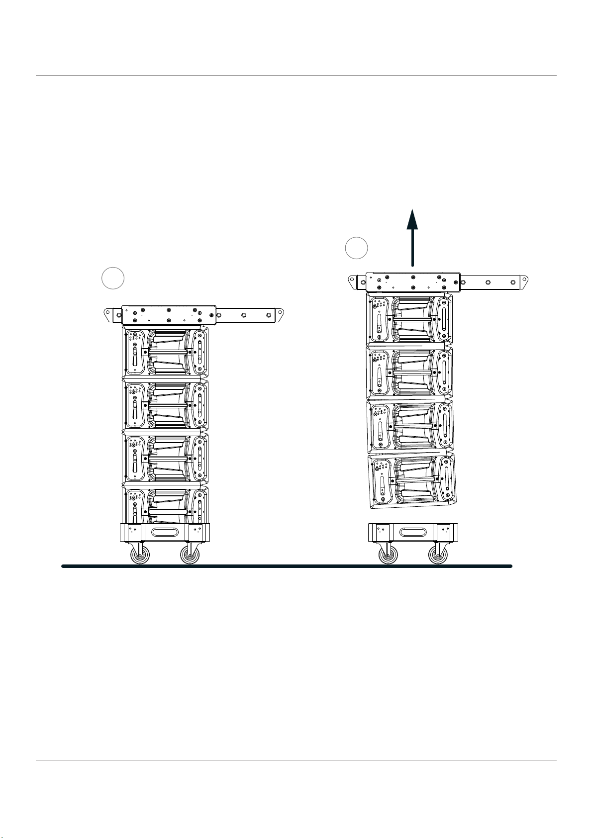
7.4 De-rigging the Array
• Taking the cluster down is a simple reversal of the rigging procedure. Bring the cluster down until the bottom
box is approximately a foot off the ground, and take the lock pins out at the front of the lowest four or more
boxes (depending on the curvature of the array) to allow the cabinets to close up, and place them in the stow
position. Lower the back motor gently to get the bottom box reasonably horizontal.
Make sure you always know the total weight of the
cluster. Never put more weight on a rigging point
than it is rated for, and always calculate how much
weight is on each rigging point.
• Carefully lower the cluster down onto a TFS-DOLLY. Disconnect the top pins from the fourth box.
• Carefully raise the array to free the lower four boxes.
• Ensure the drop link of the bottom box is up and into its locked position. Do not land the cluster on the drop
link or you will bend the rear hinge. Do not leave the front lock pins in for trucking, always put them in the store
position.
• Leave both pins in on the rear assembly because it is designed to allow the cabinets to touch each other in a
truck rather than the rigging hardware.
• Having de-rigged each block of cabinets onto a TFS-DOLLY one by one, put the covers on and stow the NL8
links in the cover.
• Finally lower the TFS-GRID flybar into the TFS-FT900 flytrunk in, disconnect the motors and lift the motors to a
safe position above head height.
• Stow the shackles in the trunk, slide the TFS-TIP tipper bar out, put the bolts back in the trunk and replace the
tipper bar in its stowed location.
Flashline User Manual
page 29
Page 30
user manual
CF-900
Conversion frame
Flex Array
TFA-600H
Flex Array
TFA-600H
Flashline
TFS-900H
Flashline
7.5 Flex Array as Downfills
Fles Array cabinets can be deployed at the bottom of a Flashline array as downfills using the CF-900 conversion
frame.
Flashline User Manual
page 30
Page 31

user manual
Flashline
8. The 20000DP AMPLIFIER
8.1 Main features
The 20000DP incorporates a number of sophisticated technologies to ensure the best possible performance
and many years of reliable operation. The following section summarizes the benefits of each feature; additional
information is available in the reference manuals.
8.1.1 Amplifier Platform
The 20000DP features extraordinary power density, patented Class TD® output stages, Regulated Switch Mode
Power Supply (R.SMPS™), the high-efficiency Intercooler® copper-finned cooling system, and a full suite of
protection features. Signal inputs are analog, AES digital, and Dante digital audio network; loop-through outputs or
redundant pairs are provided for each input type.
Please refer to the 20000DP Operation Manual for further information.
8.1.2 Amplifier DSP (Digital Signal Processing)
Various features are controlled by the on-board DSP, some of which are summarized in this section.
8.1.2.1 Input Gain (Sensitivity)
Input gain (sensitivity) is set in the digital domain, and may be controlled via the Lake Controller software or frontpanel interface.
8.1.2.2 ISVPL™
The Inter-Sample Voltage Peak Limiter (ISVPL) tailors each power output to the characteristics of the connected load.
Please refer to the 20000DP Operation Manual for further information.
8.1.2.3 Load Verification & Performance Monitoring
A comprehensive set of proprietary DSP-based tools are provided for load verification and real-time performance
monitoring. These functions utilize LoadLibrary, a comprehensive database for each loudspeaker component of the
connected load (usually one or more band-limited drivers in a multi-way system).
Using this data and a brief test signal, LoadSmart compares actual response to predicted response, identifying any
malfunctioning components or connection errors. During the performance, SpeakerSafe™ monitors real-time load
status, including temperatures of the amplifier stages as well as magnets and voice coils of connected loudspeakers.
This allows operators to avoid power compression and identify potential problems.
Please refer to the Lake Controller Operation Manual for detailed information on load verification and real-time
performance monitoring functionality.
8.1.3 Lake Processing and Controller
Flashline User Manual
page 31
Page 32

user manual
Flashline
The 20000DP integrates seamlessly into the Lake Processing environment. Two processing modules offer precise
settings for gain, delay, crossover settings, equalization and limiting. Lake processing features incorporated in each
module include Raised Cosine Equalization™, linear phase crossovers, and LimiterMax™ loudspeaker protection.
The Super Module feature allows hardware processing modules in two or more separate devices to function as
a single module in the Lake Controller software. Please refer to the Lake Controller Operation Manual for further
information.
8.1.4 Lake Analyzer Bridge
Lake Controller software provides integration with third-party real-time analyzers, providing simultaneous
measurement display and EQ adjustment via the Lake Controller. The third-party measurement tools that can be
integrated via the Analyzer Bridge include:
• Smaart Live Version 5.4
• Live-Capture Light / Live-Capture Pro
Smaart, distributed and supported by Rational Acoustics, provides real-time sound system measurement,
optimization and control. Smaart combines several powerful audio frequency measurement and analysis tools.
Live-Capture, created by WaveCapture, offers easy-to-use software and measurement tools for sound engineers,
installers, consultants and designers. The Lake Analyzer Bridge in conjunction with Live-Capture Light provides a
completely free spectrum analyzer via your Lake Controller software interface.
8.1.5 Dante™ Audio Network
The 20000DP includes Dante digital audio networking as standard. Utilizing the latest advances in Ethernet
technology, Dante offers simplified system configuration and extremely low latency while delivering very high
quality uncompressed digital audio across the Lake network. The Zen™ automatic configuration feature enables
plug-and-play setup without third-party DHCP or DNS servers. Dante is compatible with high-bandwidth networks,
allowing large numbers of audio channels to be distributed alongside control and analyzer data.
8.2 Additional Documentation
This document, the 20000DP Quick Start & Field Reference Guide, serves as a basic introduction to the installation
and operation of the 20000DP Powered Loudspeaker Management system. More detailed information is available
in the comprehensive 20000DP Operation Manual, which serves as the primary reference source for detailed
information on the installation and operation of the 20000DP Powered Loudspeaker Management system.
If you intend to use the device as part of a networked system, or access features via the Lake Controller, please refer
to the various supporting documents which can be located via these methods:
• Start > Programs > Lake Controller > Documentation (after installing Lake Controller software)
• On the Installer CD-ROM or the downloaded software installer
• Online at: http://labgruppen.com/index.php/products/documentation/
Flashline User Manual
page 32
Page 33

user manual
Flashline
9. Amplifier Installation
9.1 Unpacking
Carefully open the shipping carton and check for any damage to the device or the supplied accessories. Every
Turbosound product is tested and inspected before leaving the factory and should arrive in perfect condition. If any
damage is discovered, please notify the shipping company immediately. Only the consignee may initiate a claim
with the carrier or their insurers for damage incurred during shipping. Save the carton and packing materials for the
carrier’s inspection.
In addition to the 20000DP amplifier, the shipping carton include the following items:
• 20000DP Quick Start & Field Reference Guide
• AC mains lead (power cable) with Neutrik® powerCON® connector
• Rear brackets for additional rack support (pair) along with associated mounting hardware
• Software Installer and Documentation CD-ROM
Please keep the original carton and associated packaging to facilitate shipping of the device should the need arise.
9.2 Mounting
Airflow for cooling the 20000DP is from front panel (intake) to rear panel (exit). Please ensure that no object, such as
rack doors or lids are placed at the front or rear of the rack to ensure that airflow is maximized. This device has no
top or bottom vents and therefore may be stacked directly on top of each other. Sufficient space should be available
at the front of the rack to accommodate the handles, and at the rear to accommodate connectors and cables;
allowance must be made for cable or loom bends within a rack.
9.3 Rear Mounting
Two rear support brackets along with associated mounting hardware are included with the 20000DP, as shown in
Figure 1; it is recommended that these are used wherever possible. Fit the brackets to the vertical rails at the rear of
the rack. Figure 2 and Figure 3 show the fitting options for fixed and removable installation. The support brackets
are reversible and may be fitted to point either to the front or rear of the rack; the orientation used depends on the
rack depth and position of the rear rack rails. Two mounting methods are possible; note that the method shown in
Figure 2 additionally provides extra security against unauthorized removal. For situations where rapid removal and
replacement is required, the method shown in Figure 3 should be used.
Flashline User Manual
page 33
Page 34

user manual
Flashline
Figure 1: Rear Support Bracket and Mounting Hardware
Figure 2: Use washer for permanent installation
Figure 3: Use tube for slide-on installation
Flashline User Manual
page 34
Page 35

user manual
Flashline
9.4 Cooling
9.4.1 Overview
The 20000DP uses a forced-air cooling system with airflow from front to rear, allowing high continuous power levels
without thermal problems. Front-to-rear airflow is preferable as air at the front of a rack is cooler than that at the
rear in nearly all situations; never attempt to reverse the airflow. The operation of the cooling system is dependent
on front-to-rear airflow; it will not function effectively with external airflow in the opposite direction.
Make sure an adequate air supply is provided in front of the 20000DP, and that the rear of the amplifier has sufficient
space to allow air to escape. If the amplifier is rack-mounted, never operate the unit with any front or rear rack doors
or covers in position. It is recommended to keep the ambient temperature around the amplifier as cool as possible.
An increased temperature can have a significant negative impact on the expected lifetime on the components inside
the amplifier.
Fit solid blanks (not ventilation blanks) to unused rack
spaces to ensure effective air circulation. Leaving
gaps in between items of equipment degrades the
effectiveness of forced-air cooling.
If installing one or more 20000DP amplifier in a rack with other fan-cooled equipment, be sure that all the other
equipment also uses front-to-rear airflow for cooling. If this precaution is not observed, there is a risk of overheating,
as units with the reverse airflow will be drawing in air which has already been heated by the amplifiers.
9.4.2 Temperature Sensing and Protection
The 20000DP is equipped with a sophisticated temperature sensing system which protects it from any overheating
which may occur as a result of inadequate ventilation.
9.5 Operating Voltage
The 20000DP is equipped with a universal power supply operating from 80 to 265 V. Only connect the mains cable
(AC cord) to an AC source of the voltage shown on the label. The 20000DP uses primary switching, which means the
mains power is rectified on the primary side of the transformer. This makes the power supply insensitive to mains
frequency variation, and it will operate normally on line frequencies from 45 to 75 Hz. If the mains plug (AC plug)
fitted to the mains cable (AC cord) is not appropriate for your country, it can be removed and a locally-sourced one
fitted instead, observing the color coding in the table below:
PowerCON Pin 230V version 115V version
L Brown Black
N Blue White
E Green/Yellow Green
If you are not 100% confident of your competence to replace the mains plug (AC plug), the task should be carried
out by qualified personnel.
Once a suitable AC power supply is connected, the device can be turned on using the front panel power button.
When turned on, a diagnostic routine is performed and the power button LED changes from red (Standby) to green
(Active).
Flashline User Manual
page 35
Page 36

user manual
Flashline
In-rush current is controlled and limited during the
soft-start sequence. This enables multiple amplifiers
on the same AC mains circuit to be turned on
simultaneously.
9.6 Grounding
Analog inputs feature Iso-Float™ ground isolation, a technology which combines the benefits of transformercoupled isolation with the advantages of clean, direct-coupled inputs. The audio converters are galvanically isolated,
and not connected to the main ground. High-speed transformers and opto-isolators create a barrier between the
device and the outside electrical environment.
The Iso-Float feature is activated by default, but may
be disabled via the Lake Controller software, or via
the front panel menu.
Use correctly-shielded balanced audio input connections to minimise hum and interference. NEVER disconnect the
earth (ground) pin on the mains cable (AC power cord).
10. Product Overview
10.1 Front Panel Overview
The front panel controls are clustered around a daylight readable LCD, allowing adjustment and monitoring of
the majority parameters and meters. The two clusters of controls on either side of the LCD include five dedicated
function buttons, eight dynamic function buttons with embedded LEDs and a rotary data encoder .
Figure 4: Front Panel Overview
10.1.1 Handles
Flashline User Manual
page 36
Page 37

user manual
Flashline
Two sturdy metal handles are fitted to the front panel. The handles should be used when carrying the device, and
when fitting it in or removing it from a rack. Ensure that any door or removable rack front cover has sufficient depth
to clear the handles.
10.1.2 Dust Filters
Two dust filters are fitted behind metal covers. To remove the covers, loosen the thumbscrews located behind the
handles. Once detached, the dust filter elements can be removed for cleaning.
NEVER operate this device without the dust filters in
place.
10.1.3 Display
The display illuminates when the device is on. The LCD, function buttons, and the rotary encoder provide realtime control and monitoring of most parameters. The LEDs embedded in the function buttons indicate available
menu options, provide confirmation of Controller communication, and indicate various faults and warnings. The
brightness and contrast of the display and front panel LEDs can be adjusted via the front panel menu.
10.1.4 Standby
The 20000DP is powered on and to standby using the top-left button, or via the Lake Controller.
10.1.5 Mute Enable
Select MUTE ENABLE to allow the dynamic function buttons to operate as mute controls for the Module inputs and
power output channels. The MUTE ENABLE button flashes when the mode is selected; a subsequent press deselects
this mode. If left activated, MUTE ENABLE mode will automatically disable two minutes after the last mute action.
10.1.6 Meter
The METER button scrolls through four alternative meter views: Home View, Module View, Temperature View and
Input View. Pressing METER from Menu Mode returns the screen to Meter Mode with Home View displayed.
10.1.7 Menu
After pressing the MENU button, the LCD will display the top level menu. In Menu Mode the function buttons enable
access to various information and functions.
10.1.8 Dynamic Function Buttons with LEDs (Left of LCD)
The function of these buttons change according to the currently selected view or menu.
• In Menu Mode they are set for menu navigation and for parameter selection
• In Meter Mode they provide Module input mute/unmute functionality in conjunction with MUTE ENABLE
The LED in the top button provides Frame fault and warning indications. The middle two buttons provide Module
input mute functionality, mute indication and faults and warning indications relating to the 20000DP inputs. The
bottom button is used only in Menu Mode or to lock the front panel buttons.
Flashline User Manual
page 37
Page 38

user manual
Flashline
Please refer to the Operation Manual for further details.
10.1.9 Dynamic Function Buttons with LEDs (Right of LCD)
The function of these buttons change according to the currently selected view or menu.
• In Menu Mode they are used for menu navigation and for parameter selection
• In Meter Mode they provide output mute/unmute functionality in conjunction with MUTE ENABLE
All LEDs provides mute, clip, fault and warning indications for the power outputs channels.
10.1.10 Communication LED
The high-intensity white LED illuminates white to indicate that the Module/Frame is selected in the Lake Controller;
it flashes white to indicate communication with the Lake Controller. The brightness of the LCD and communications
LED can be adjusted in the Frame page of the Main Menu on the front panel.
10.1.11 Rotary Encoder
The rotary encoder is used to modify various parameters (e.g. input level) via the menu. When a menu item is
selected that permits adjustment of parameter values, the ring around the rotary encoder illuminates. In Home View
the encoder can be used to scroll through the Meter Views.
10.1.12 Exit
The EXIT button is used primarily while navigating the menu system in Menu Mode; pressing EXIT will return the
menu up one level. In Meter Mode, pressing EXIT returns the metering display to the default Home View.
10.2 Back Panel Overview
5 1 324 6 7 8
LINK SEC PRIM ACT LINK ACT
SWITCHED 10/100 Base-TX
100/240V 2400/2950W
50-60Hz
Must be grounded/earthed
Made in Sweden
CLASS 2 WIRING
1+/- CH 1+/2+/- CH 2+/-
Ser. N:o
SPEAKER OUTPUTS
1+/- CH 1+/2+/- CH 2+/-
Removed!
3+/- CH 3+/4+/- CH 4+/-
1+/- CH 3+/2+/- CH 4+/-
INPUT 1 INPUT 2 LINK
ANALOG WITH ISO-FLOAT
1 LINK 2
PIN 1: SCRN 2: POS 3: NEG
TM
INPUT 1-2 LINK 1-2
AES/EBU
Figure 5: Back Panel Overview
Flashline User Manual
page 38
Page 39

user manual
Flashline
10.2.1 Connectors
10.2.1.1 Analog Inputs
Analog inputs are available on two standard XLR3F latching connectors. The inputs are electronically balanced and
feature Lake Iso-Float circuitry. The impedance is 20 kohms, and the inputs can accept a maximum input level of +26
dBu.
10.2.1.2 Analog Links
Two latching XLR3M connectors are fitted adjacent to the analog input connectors. These are paralleled to the input
connectors to provide an unprocessed analog loop-through to feed additional amplifiers, or other equipment.
10.2.1.3 AES3 Input
A latching XLR3F connector is provided which accepts an AES3 digital audio signal. Input impedance is 110 ohms,
please ensure that 110 ohm digital audio cables are used; standard XLR microphone cables are rarely suitable for
reliable digital audio transmission.
AES3 is a stereo digital format, and therefore both
PLM inputs are fed via a single connector. Selection of
the analog or digital inputs is made via the front panel
display or control software.
10.2.1.4 AES3 Link
A latching XLR3M connector is fitted adjacent to the AES3 input connector. This is paralleled to the input connector
to provide an unprocessed AES3 loop-thru to feed further amplifiers, or other equipment. An AES3 110 ohm
termination load is enabled by default when the amplifier is the last unit connected within an AES3 daisy-chained
system. The termination may be disabled, if desired, via the front panel menu and within the Lake Controller
software.
10.2.1.5 SpeakON Connectors
The 20000DP is provided with Neutrik speakON® power output connectors, and allows for Bridge Mode operation
which is activated from the Lake Controller software. Please refer to the Lake Controller Operation Manual and the
20000DP Operation Manual for further information on Bridge Mode.
The power outputs are simultaneously available on a single 8-pole speakON connector, and on two 4-pole speakON
connectors. The two 4-pole connectors carry the outputs of channels 1 & 2 and 3 & 4 respectively.
Bridge Mode can be enabled via the Lake Controller software, please refer to the Lake Controller Operation Manual
and to section 8.1.2 of this Operation Manual for further details on standard and Bridge Mode wiring for speakON
connectors.
10.2.1.6 Primary Network Connector
The primary Neutrik RJ45 etherCON® con nection provides integration into an Ethernet control network which
may include other Lake Processors and the Lake Controller software. Network connection permits full control of all
functions along with real-time metering from a remote position. This device supports the Dante audio networking
protocol, which allows transmission of multichannel, high-definition digital audio over the same Ethernet
connection.
Flashline User Manual
page 39
Page 40

user manual
Flashline
Use the primary connector when using a star network topology, consisting of individual Cat-5e connections between
the devices and an Ethernet switch. Alternatively this connection can be used to daisy chain directly to another Lake
Processor. The daisy chain topology should not be used with Dante.
For a technical reference of the Ethernet Port, please refer to the 20000DP Operation Manual. Additional information
is available in the Lake Network Configuration Guide.
The Ethernet ports operate at the Ethernet data rate of
100 Mbps, and allow straight or crossed network
cables. Two LEDs above each port indicate valid
network connection (LINK) and network activity (ACT).
10.2.1.7 Secondary Connector
The secondary network connector can be used to daisy-chain multiple 20000DPs, LM 26 and legacy Lake devices.
Alternatively, a Dante dual-network topology can be created by connecting all secondary network connectors to a
separate Ethernet switch, ensuring full redundancy in the event of a network component failure.
Additional processor configuration is required for a
dual redundant network setup. See the Lake
Controller Operation Manual for further details.
For a technical reference of the Ethernet Port, please refer to the 20000DP Operation Manual. Additional information
is available in the Lake Network Configuration Guide.
When connecting multiple devices to an Ethernet
network, care must be taken NOT to create a closed
loop which causes network malfunction.
10.2.1.8 Mains Power Connector
The mains power AC input is via a Neutrik powerCON connector, rated at 32 A. The power supply must be
connected to AC mains using a power cable with a correctly wired plug for the country of operation.
Flashline User Manual
page 40
Page 41

user manual
Module Output:
Gain/Delay
Phase Rev
Mute
Module Output:
Gain/Delay
Phase Rev
Mute
Module Output:
Gain/Delay
Phase Rev
Mute
Module Output:
Gain/Delay
Phase Rev
Mute
Module Output:
Gain/Delay
Phase Rev
Mute
Module Output:
Gain/Delay
Phase Rev
Mute
Flashline
11. Signal Flow and Lake Processing
11.1 Signal Flow
Figure 5-1 and Figure 5-2 depict the audio signal flow inside a 20000DP. It is worth noting that this sophisticated
device provides seven points in the signal chain where the signal level can be adjusted, muted or disconnected.
Important information regarding correct setting of the gain structure can be found in the 20000DP Operation
Manual.
Output EQ
Analog 1/2
AES 1
AES 2
Dante X
Dante Y
Analog 1/2
AES 1
AES 2
Dante X
Input
Router
1
(Mute)
Input
Router
2
(Mute)
Input
Mixer A
Input
Mixer B
Module:
Gain
Phase Rev
Mute
Module:
Gain
Phase Rev
Mute
EQ Delay
EQ Delay
Dante Y
Figure 6: Signal Flow Diagram
11.2 Level Adjustments & Mute Points
Input Router Stage – Input selection and MUTE
Input Mixer Stage – Router ON/OFF connection to mixer and gain settings
Module Input Stage – Mute and gain settings
Output EQ
Output EQ
Crossovers
Output EQ
Output EQ
Output EQ
Module Output Stages – Mute and gain settings
Output Router Stage – Output ON/OFF routoing connections
Attenuation Stage – Power output channel mute and attenuation settings
Amp Gain Stage – Amplifier gain control
Flashline User Manual
page 41
Page 42

user manual
Output Routing
AMP
Attenuator
Mute
Phase Rev
Attenuator
Mute
Phase Rev
Attenuator
Mute
Phase Rev
LoadSmart
SpeakerSafe
LoadSmart
SpeakerSafe
LoadSmart
SpeakerSafe
LoadSmart
SpeakerSafe
Amp Gain
Amp Gain
Amp Gain
Amp Gain
Attenuator
Mute
Phase Rev
AMP
AMP
AMP
ISVPL
ISVPL
ISVPL
ISVPL
LimiterMax
RMS / Peak
Module Output:
Gain/Delay
Phase Rev
Mute
LimiterMax
RMS / Peak
Module Output:
Gain/Delay
Phase Rev
Mute
LimiterMax
RMS / Peak
Module Output:
Gain/Delay
Phase Rev
Mute
LimiterMax
RMS / Peak
Module Output:
Gain/Delay
Phase Rev
Mute
LimiterMax
RMS / Peak
Module Output:
Gain/Delay
Phase Rev
Mute
LimiterMax
RMS / Peak
Module Output:
Gain/Delay
Phase Rev
Mute
Flashline
If the required audio signal is not passing
correctly, verify the connection, mute and
volume settings at all seven stages.
11.3 Power Output Section: Limiting and Sensitivity
The Current Peak Limiter (CPL) dynamically limits the drive to the power stage based on three parameters: sensed
output current level, feedback from the output stage, and sensed voltage clip from the ISVPL. This ensures that
power output is maintained within the design limits of the amplifier.
The adjustable Inter-Sample Voltage Peak Limiter (ISVPL) sets the 20000DP’s maximum output voltage and therefore
also the maximum output power. The ISVPL setting is made via MENU > MODULE > LIMITERS > ISVPL, and can also
be set from the Lake Controller software.
The sophisticated output section monitors faults and generates warnings when appropriate; warnings are displayed
on the front panel of the 20000DP and also sent as messages over the control network. In the rare event that
maximum ratings are significantly exceeded, the amplifier will shut down until the condition has been rectified
or the incorrect setting has been readjusted. Sensing circuits also transmit local output power stage temperature,
processor card temperature, and PSU temperature to the appropriate protection circuits. The table below lists
analog input sensitivity in dBu and Vrms for various Amp Gain settings and maximum/minimum ISVPL settings,
assuming an analog input headroom of 26 dBu.
Flashline User Manual
page 42
Figure 7: Signal Flow Diagram (part 2)
Page 43

user manual
Flashline
INPUT SENSITIVITY
ISVPL SETTING 194V 193V 153V 17.8V
GAIN (dB) dBu Vrms dBu Vrms dBu Vrms dBu Vrms
+44 +1.0 0.87 +0.9 0.86 -1.1 0.68 -19.8 0.08
+41 +4.0 1.22 +3.9 1.22 +1.9 0.96 -16.8 0.11
+38 +7.0 1.73 +6.9 1.72 +4.9 1.36 -13.8 0.16
+35 +10.0 2.44 +9.9 2.43 +7.9 1.92 -10.8 0.22
+32 +13.0 3.45 +12.9 3.43 +10.9 2.71 -7.8 0.32
+29 +16.0 4.87 +15.9 4.84 +13.9 3.84 -4.8 0.45
+26 +19.0 6.88 +18.9 6.84 +16.9 5.42 -1.8 0.63
+22 +23.0 10.90 +22.9 10.84 +20.9 8.59 +2.2 1.00
11.4 Lake Processing and Control
As outlined in section 2.2.3, this device integrates seamlessly into the Lake Processing environment, providing all
features, functionality and connectivity associated with all Lake Processors. The internal Lake Processing includes
programmable crossovers, EQ, dynamics and other functions, and can be fully controlled via the supplied Lake
Controller software. Additionally, many functions can be controlled or accessed directly via the front panel.
The Lake Controller Operation Manual and Lake Network Configuration Guide are supplied on the accompanying
CD-ROM and additional documentation is available from the Start Menu after software installation.
11.5 Modules and Frames
11.5.1 Overview
A Frame represents one physical Lake Processor (e.g. a 20000DP). A maximum of two Modules are contained within
each Frame; these are referred to as Module A and Module B. The number of Modules shown in a given Frame is
dependent upon the signal processing configuration of that Frame.
Each Module can be configured as a Classic Crossover (Bessel, Butterworth, Linkwitz-Riley), as a Linear Phase
Crossover, or as multiple full bandwidth Auxiliary Outputs. The default configuration is 2 x 2-Auxiliary Output
Modules, providing a total of four module outputs.
11.6 LoadLibrary™ and Fingerprints
In addition to the standard loudspeaker presets (Module files), the Lake Controller also includes a set of enhanced
Module files specifically for use with the 20000DP.
These supplementary Module files, known as the LoadLibrary, incorporate both Lake DSP parameters along with
20000DP specific data; LoadLibrary Module files include parameter settings for the 20000DP’s Amplifier Gain
and ISVPL limiter. Additionally, LoadLibrary loudspeaker types may also include data relating to the electrical
characteristics of a particular loudspeaker.
Flashline User Manual
page 43
Page 44

user manual
Flashline
Electrical characteristic data is used to enable load verification (LoadSmart) and monitoring facilities (SpeakerSafe)
to be performed on the 20000DP. This data set is termed a Fingerprint. When a 20000DP-specific loudspeaker type is
loaded, its Fingerprint load characteristics are included. These load characteristics are stored in a file with a “.mdl”
suffix and are loaded simultaneously with the module file.
LoadLibrary Modules and standard Module files are cross-compatible, although when a LoadLibrary Module is
loaded into a legacy Lake product the extra data within it is ignored.
11.7 Super Modules
Super Modules allow control of multiple Modules of the same type, distributed across multiple Frames, as a single
entity within the Lake Controller software. A change made in the Super Module is replicated across all assigned
Modules, resulting in improved efficiency in system configuration and a reduction of on-screen icons within the
Lake Controller software.
The key benefit of this feature is the ability to connect and control crossovers, levels and EQ across multiple
hardware devices simultaneously from the Lake Controller. For example, one device may be driving sub and lowfrequency speakers, while another device controls mid-range and hi-frequency drivers. Using a single adjustment
the crossover points between the two devices can be changed simultaneously.
Please refer to the Lake Controller Operation Manual for further information regarding Super Modules.
11.8 Loudspeaker Crossover Configuration Overview
The Lake Processing system may be configured with up to two inputs and up to six Module outputs, although the
number of power outputs will be either two or four depending on the PLM model being used. To make use of the
extra processing channels, multiple hardware devices may be connected together using the Super Module feature
as summarized in section 5.3.3.
Each set of processing elements is referred to as a Module and can be configured as crossovers, full bandwidth
auxiliary outputs, or a combination of the two. The relationship between inputs and outputs is defined via the Lake
Controller or via the front panel Input Config Menu.
The Lake Processing system provides two distinct categories of crossovers:
• Infinite Impulse Response filters (IIR) such as the classic Bessel, Butterworth or Linkwitz-Riley types; these are
available with slopes ranging from 6 dB/octave to 48 dB/octave.
• Finite Impulse Response filters (FIR) providing zero phase shift with steep transition slopes at the crossover
frequencies. These are also referred to as Linear Phase Crossovers.
11.9 Files and Presets
The Lake system provides various methods for storing and recalling Module, Frame, or system-wide data. A
overview is provided below; for further information please refer to the Lake Controller Operation Manual.
11.9.1 Module, System and Sub-System Configuration Files
Module, System and Sub-System Configuration files are stored on the Lake Controller PC, and data is passed across
the network when recalling or storing these type of files.
Flashline User Manual
page 44
Page 45

user manual
Flashline
• A Module file is the smallest set of data that can be stored and recalled; it contains crossover, gain, delay, and
limiter information for an individual loudspeaker. A Module file may be recalled into other Lake devices. It is not
possible to store a Module File directly on the hardware device.
• A System or Sub-System Configuration File contains a set of Module file information in addition to Frame related
information such as I/O routing, along with Group control information.
11.9.2 Frame and System Presets
This device allows the complete processor configuration to be stored as a Frame Preset on the hardware unit itself.
Presets can be recalled via the front panel (please refer to section 7.11.7) or via the Lake Controller software (please
refer to the Lake Controller Operation Manual).
A maximum of 100 Frame Presets can be stored on this device. The data within a Frame Preset includes the
configurations of both Modules in the Frame, including all levels, crossover, EQ, input mixer, output routing, and
all other Module, Frame and Group parameters. As Frame Presets are stored in the device, complete processor
configurations may be recalled without the need to connect the device to a PC.
Using the System Presets function in the Lake Controller, entire system configurations can be stored and recalled
across a network of LM 26, PLM, Mesa Quad EQ, Contour Pro 26, and Dolby Lake Processors. This enables fast
retrieval and switching of entire system configurations as minimal data is being sent between the Controller and
Processors.
Flashline User Manual
page 45
Page 46

user manual
Flashline
12. Lake Controller Software
12.1 Introduction
This section describes installation of the Lake Controller software, input and output connections, basic functionality,
and setup instructions. The information provides a basic level of understanding of the system architecture along
with configuration instructions for a basic system application. The tutorial in section 6.4 provides a step-bystep example for configuring this device for use with a generic professional sound system. Please refer to the
documentation listed in section 2.3, which provides detailed information on all features and functionality.
12.2 Lake Processing and Control
The 20000DP contains an integrated Lake loudspeaker management system, providing crossovers, EQ, dynamics
and other functions. Primary control is via the supplied Lake Controller software, although many functions can
be accessed via the front panel interface. The Lake Controller software allows all parameters to be configured,
controlled and monitored; please refer to the Lake Controller Operation Manual for further details. The Lake Network
Configuration Guide provides information regarding connection of one or more Lake Processors to a PC via an
Ethernet network.
12.3 Installing the Lake Controller Software
12.3.1 Overview
The supplied memory stick contains the Lake Controller software package. This should be installed on any PCs
that will be used to control and monitor the Lake Processor network. In a situation where multiple networked Lake
Processors are involved, this will generally be a Tablet PC.
The minimum recommended computer specifications are:
• 1 GHz or faster
• 512 MB RAM or greater
• 128 MB video RAM or greater
• Windows XP, Windows Vista or Windows 7
• DirectX® 8.1 or later
• 100 Base-T wired Ethernet adapter and/or 802.11 wireless Ethernet adapter
When using large Lake processor systems it is recommended that a computer exceeding the minimum
specifications is used. If you are unsure about installing PC software, please contact an IT specialist.
12.3.2 Software Installation
The Lake Controller software is installed by allowing the auto-setup routine to run. Select INSTALL then LAKE
CONTROLLER SOFTWARE on the software installation screen that is displayed. For most installations, the suggested
default installation paths can be accepted.
Flashline User Manual
page 46
Page 47

user manual
Flashline
The latest software can be downloaded from http:// labgruppen.com/index.php/support/software_firmware/ after
completing an online registration form. It is recommended that all users verify they are using the latest version of
software.
Once the software is installed, the application is launched by double-tapping the LAKE icon on the Windows
desktop. Please refer to the Lake Controller Operation Manual for further details on software installation and PC
configuration.
12.3.3 Software and Firmware updates
Regular software and firmware updates are available for the Lake Controller software and 20000DP amplifier. Please
check for updates regularly to ensure you have the latest features and improvements.
Registered users will receive email notification of updates as they become available. The latest updates are also
available from http://www.labgruppen.com/index.php/support/software_firmware. Please refer to the Lake Controller
Operation Manual for further details on the firmware upgrade procedure.
12.3.4 Ethernet Configuration
This device provides control, monitoring and digital audio functionality via an Ethernet network. For further
information on the setup and configuration of an Ethernet network, please refer to the Lake Controller Operation
Manual and the Lake Network Configuration Guide.
12.4 Gain Structure
The 20000DP architecture provides gain adjustments at various points in the signal path and therefore, various
places for muting and level adjustment. Each mute or gain adjustment point serves a different purpose.
Detailed information on signal flow and gain structure is available in the 20000DP Operation Manual. The signal
flow diagrams in chapter 5 (Figure 5-1 and Figure 5-2) are useful signal path references, and the following sections
describe the various adjustment points, all of which are available via the Lake Controller software.
12.4.1 Input Headroom (Analog Inputs Only)
Input Headroom should be set to 12 dBu if the source can be limited to 12 dBu; otherwise it should be set to 26
dBu. This setting does not affect the other gain stages, or the overall noise floor; it allows control of the appropriate
headroom at the input stage only.
12.4.2 Input Mixer
Input Mixer gains can remain at 0.00 dB for most configurations; if only one input channel is used per Module, the
other can be set to -INF.
12.4.3 Module Input Gain
Input Gain is used to adjust the level between different speaker cabinets in the system. This gain can remain at 0.00
dB unless a lower level is required for the cabinet/s driven by this Module.
12.4.4 Module Output Gain (Levels)
Flashline User Manual
page 47
Page 48

user manual
Flashline
Factory and User Gain are provided for each Module output. These two stages provide a level of security and control
for the system designer (Factory) and a further level of adjustment for the user (User), both of which combine to
balance the level between frequency bands in a multi-way crossover.
Generally, output gain values are configured within a Module / loudspeaker preset file and should not need to be
adjusted further.
12.4.5 Attenuator
An attenuator gain adjustment is provided for each power output channel in the 20000DP. This control replaces the
traditional volume control found on conventional amplifiers and should typically be left at 0 dB during use.
12.4.6 Amp Gain
The Amp Gain corresponds to the gain adjustment in a conventional separate loudspeaker processor and amplifier
system. When using a pre-defined Module loudspeaker preset file, the Amp Gain settings will normally remain as
defined in the file. The limiter and output gain settings of the Module were configured with this gain setting and
will not be automatically compensated if changes are made. This configuration scheme, though unusual, allows for
compatibility with legacy Dolby / Lake products.
12.5 Gain / Level Optimization
12.5.1 Maximize Volume Capability
To maximize the volume capability of the device, ensure there is sufficient headroom in the signal path to avoid
clipping before the limiters engage. It must be possible to achieve enough gain through the device to engage
the limiters and realize a high average SPL. As an optimal setting, allow for a headroom of 10 dB or more for all
channels; the simplest way to accomplish this is to increase the Module input gain.
12.5.2 Minimize Noise
To help provide the best volume to noise ratio, use an AES or Dante digital input signal wherever possible. If using
analog inputs, ensure that unused or unnecessarily high headroom is not introduced at the input to the device. If full
or high average power is not required, the Module input gain may be reduced.
Flashline User Manual
page 48
Page 49

user manual
Flashline
13. Warranty and Support
13.1 General
This product is manufactured by Lab.gruppen, and it is warranted to be free from any defects caused by
components or factory workmanship, under normal use and service, for a period of three (3) years from date of
purchase from an authorized Lake dealer.
If the product fails to perform as specified during the warranty period, Lab.gruppen will undertake to repair, or at its
option, replace this product at no charge to its owner, provided the unit is returned undamaged, shipping prepaid,
to an authorized service facility or to the factory.
This warranty shall be null and void if the product is subjected to: repair work or alteration by a person other
than those authorized by us; mechanical damage including shipping accidents; war, civil insurrection, misuse,
abuse, operation with incorrect AC voltage; incorrect connections or accessories; operation with faulty associated
equipment; or exposure to inclement weather conditions. Damage due to normal wear and tear is not covered
by the warranty. Units on which the serial number has been removed or defaced will not be eligible for warranty
service.
Lab.gruppen shall not be responsible for any incidental or consequential damages. Lab.gruppen’s responsibility is
limited to the product itself. Lab.gruppen takes no responsibility for any loss due to cancellation of any events, or
rent of replacement equipment or costs due to a third party’s or customer’s loss of profit, or any other indirect cost
or losses however incurred.
Lab.gruppen reserves the right to make changes or improvements in design or manufacturing without assuming
any obligation to change or improve products previously manufactured.
This warranty is exclusive, and no other warranty is expressed or implied. This warranty does not affect the
customer’s statutory rights.
13.2 International Warranties
Please contact your supplier or distributor for this information, as rights and disclaimers may vary from country to
country.
13.3 Technical Assistance and Service
13.3.1 International Service
If your Lab.gruppen product requires repair, contact your Lab.gruppen dealer or distributor, or contact Lab.
gruppen by fax or email to obtain the location of the nearest authorized service centre.
Flashline User Manual
page 49
Page 50

user manual
Flashline
14. Maintenance
14.1 Removal of the drive units
Remove the screws securing the top and bottom butterfly plates. Remove the screws securing the mid/high section
and carefully lift out and away from the cabinet. Disconnect all cables and make a note of the polarity and location
for later reconnection. The high frequency compression drivers, high-mid drivers and low-mid drivers can now all
be accessed for servicing.
Remove the screws holding the rear driver doors in place and remove the access doors. The low frequency drivers
can now be accessed for servicing.
Flashline User Manual
page 50
Page 51

15. Technical Specifications
TFS-900H TFS-900B
DIMENSIONS 360mm x 1240mm x 570mm 599.5mm x 1246.5mm x 1140mm
NET WEIGHT 102kg (224.4 lbs) 154kg (338.8lbs)
user manual
Flashline
COMPONENTS 2 x 12” (305mm) bass driver
4 x 6.5” (165mm) low drivers
2 x 6.5” (165mm) mid drivers on Dendritic device
3 x 1” (25mm) high drivers on Dendritic device
FREQUENCY RESPONSE 70Hz - 18kHz ±3dB, 60Hz - 20kHz ±10dB 35Hz - 150Hz ±3dB, 30Hz - 200Hz ±10dB
NOMINAL DISPERSION 90° horizontal, vertical dispersion dependent on
array
POWER HANDLING Optimised for 20000DP Optimised for 20000DP
SENSITIVITY
(FULL SPACE)
CALCULATED MAXIMUM
SPL (PER ELEMENT WHEN
USED IN AN ARRAY)
NOMINAL IMPEDANCE High: 18Ω, Mid: 12Ω, Low: 8Ω, Bass: 8Ω 2 x 8Ω
CONSTRUCTION 15mm (5/8”) birch plywood finished in TourTough
High: 111dB, Mid: 109dB, Low: 104dB, Bass: 10dB 107dB
147.5dB peak 151dB peak
IP54
2 x 18” LF drivers
18mm (3/4”) birch plywood painted in TourTough
IP54
GRILLE Stainless steel IP54 Stainless steel IP54
CONNECTORS 2 x Speakon NL8, one band per pair 2 x Speakon NL4, one driver per pair
SPARES AND ACCESSORIES LS-1229 12” bass loudspeaker
LS-6510 6.5” low frequency loudspeaker
LS-6507 6.5” mid frequency loudspeaker
CD-115 1” high frequency compression driver
Flashline User Manual
page 51
Page 52

user manual
Flashline
NOTES
Flashline User Manual
page 52
Page 53

NOTES
user manual
Flashline
Flashline User Manual
page 53
 Loading...