

Page 1

TFS-780 Flashlight System
User Manual
Turbosound Ltd.
Star Road, Partridge Green
West Sussex RH13 8RY England
Tel: +44 (0)1403 711447 Fax: +44 (0)1403 710155
web: www.turbosound.com
Issue 1.4 © Turbosound Limited, October 2000
Page 2

user manual
TFS-780
TFS-780 user manual
Page 2
CONTENTS
Contents............................................................................................................................... 2
Introduction ......................................................................................................................... 4
Turbosound Flashlight & Floodlight System Concepts .................................................... 4
The Loudspeaker Management System (LMS) Concept ..................................................4
TFS-780................................................................................................................................ 4
TFS-780L ..............................................................................................................................5
TFS-780H.............................................................................................................................. 5
TFL-760H .............................................................................................................................. 6
TFL-760HM and TFL-760LM downfills................................................................................ 7
TFS-780HF long throw ........................................................................................................ 7
LMS-D6 ................................................................................................................................ 7
Flashlight Flying System..................................................................................................... 7
Flying and Stacking.............................................................................................................8
Overview.............................................................................................................................. 8
Setting Horizontal Angles................................................................................................. 12
Tilting................................................................................................................................. 12
Setting Vertical Angles ..................................................................................................... 15
Arraying............................................................................................................................. 16
Procedure for flying a Flashlight array ............................................................................ 17
Bass Enclosure arraying ................................................................................................... 23
Aiming - directivity of the stack ....................................................................................... 23
Ground Stacking................................................................................................................ 25
Vertical Dispersion Considerations.................................................................................. 25
Flown Systems.................................................................................................................. 26
LMS-D6 Loudspeaker Management System................................................................... 27
Introduction ....................................................................................................................... 27
General features & facilities ............................................................................................. 27
Unpacking.......................................................................................................................... 27
Mechanical Installation..................................................................................................... 27
Front Panel functions........................................................................................................ 28
Rear Panel functions ......................................................................................................... 29
Mains Power...................................................................................................................... 29
Voltage Setting.................................................................................................................. 30
Safety Earthing.................................................................................................................. 30
AC Power Fusing............................................................................................................... 30
Powering Up...................................................................................................................... 30
Audio Connections............................................................................................................ 31
Input and Output Connector Wiring................................................................................. 31
Time correction for loudspeaker driver placement......................................................... 31
AMP-780 - Flashlight System Amplification Rack ........................................................... 32
Racking, Cables and Connections .................................................................................... 32
Options ..............................................................................................................................33
Input Connections ............................................................................................................. 33
Output Connections ..........................................................................................................34
Remote Control Connections ........................................................................................... 34
Extension Cables............................................................................................................... 35
Mains Connections............................................................................................................ 36
TMC-750 and TMC-1250 High Efficiency Audio Power Amplifier .................................. 37
General Features & Facilities............................................................................................ 37
Page 3

user manual
TFS-780
TFS-780 user manual
Page 3
Front Panel Functions TMC-750 ....................................................................................... 38
Front Panel Functions TMC-1250 ..................................................................................... 39
Rear Panel Functions ........................................................................................................ 40
Mechanical Installation..................................................................................................... 41
Mains Power...................................................................................................................... 41
Powering Up...................................................................................................................... 41
Safety Earthing.................................................................................................................. 42
Internal Fuses.................................................................................................................... 42
Voltage Setting.................................................................................................................. 42
Voltage Range ...................................................................................................................42
Current Consumption ....................................................................................................... 42
Audio Connections & Controls......................................................................................... 43
Polarity............................................................................................................................... 43
Input Impedance................................................................................................................ 43
Muting................................................................................................................................ 44
Sensitivity.......................................................................................................................... 44
Attenuation & Gain Setting .............................................................................................. 44
Signal Metering.................................................................................................................44
Output Connections .......................................................................................................... 45
Damping Factor................................................................................................................. 45
Which speaker impedance?.............................................................................................. 45
Long Speaker Lines........................................................................................................... 45
The Cooling System.......................................................................................................... 46
Filter Inspection & Maintenance ......................................................................................46
Temperature Metering & Protection................................................................................ 46
Fan Speed Setting............................................................................................................. 47
Fault Modes....................................................................................................................... 47
Troubleshooting................................................................................................................ 48
Maintenance...................................................................................................................... 50
Gaining Access..................................................................................................................50
To withdraw one of the amplifier modules..................................................................... 50
Cleaning............................................................................................................................. 50
Routine Checks..................................................................................................................50
Cleaning heatsinks ............................................................................................................ 50
Spare Parts & Accessories................................................................................................ 51
Specifications.................................................................................................................... 51
Warranty............................................................................................................................ 52
Page 4

user manual
TFS-780
TFS-780 user manual
Page 4
INTRODUCTION
Turbosound Flashlight & Floodlight System Concepts
The TFS-780 has been designed as a complete system, with integrated loudspeakers, flying
hardware, amplifier racks, cabling and digital control system. It is designed for use in all
indoor and outdoor venues, from a small club audience up to the largest arena or stadium.
The Flashlight system concept benefits from the availability of a variety of purpose-designed
loudspeaker box types, forming a flexible kit of parts that are used to build up loudspeaker
arrays to cover specific audience spaces with precisely controlled high-fidelity sound
coverage.
The Turbosound TFL (Floodlight) loudspeaker system can be used on its own as a side or
front fill, as well as being part of the Turbosound Flashlight System. The Turbosound TFL760HM high-mid downfill and the TFL-760LM low-mid downfill enclosures contain the same
components as the TFL-760H, and are used to further enhance a Flashlight array, providing
near-field coverage for the nearest audience rows.
The TFS-780HF long-throw high-mid contains the same components as the TFL-760HM, and
is used for high end far-field coverage of the furthest audience areas.
The Loudspeaker Management System (LMS) Concept
The LMS-D6 Loudspeaker Management System is more than just an electronic crossover. It
provides full digital time alignment of all components in the Flashlight/Floodlight enclosures,
to ensure a coherent acoustic output. It also incorporates a number of features which
contribute to overall system reliability and ease of setting-up.
Because the power amplifiers are included as part of the Flashlight system, the LMS-D6 is
able to utilise output limiters which are precisely matched to the system requirements, being
pre-set to prevent the amplifiers from clipping. Inputs and outputs are fully balanced,
providing isolation between the LMS-D6 and the amplifier inputs. These factors contribute to
high reliability in the adverse circumstances often encountered under arduous touring
conditions.
Flashlight TFS-780
The Turbosound Flashlight system is a complete, fully integrated sound reinforcement
system comprising loudspeakers and all necessary drive and control equipment in an
extremely compact and manageable form.
By supplying the Flashlight only as an integrated package, Turbosound has ensured absolute
compatibility between users. All Flashlight systems are identical throughout the world, and
Page 5

user manual
TFS-780
TFS-780 user manual
Page 5
equipment from different sources may therefore be freely combined without difficulty. This
provides Flashlight system owners with a considerable competitive advantage in servicing
the requirements of international touring productions, and in co-operating with other
Flashlight suppliers within the worldwide network.
The system is supplied as multiples of a unit package comprising 12 enclosures (6 bass and 6
mid-high), a single rack of four dual-channel power amplifiers, two loudspeaker management
system controllers, flying hardware, and all the requisite cables and connectors. Two of
these packages (or 24 bass and 24 mid-highs) will provide a formidable system for distant
audience coverage in large arenas, and can be integrated with Turbosound Floodlight
enclosures for short and medium range coverage. This set of components also forms a
standard building block for the construction of spherical arrays.
The controller functions as an electronic loudspeaker management system, comprising a
24dB per octave crossover, with factory preset limiters matched to the power amplifiers,
digital time-alignment and electronically balanced inputs and outputs. The power amplifiers
are supplied as a set of four in a 19" rack with all necessary wiring and multi-pin connectors.
The loudspeakers are of six types, of compatible dimensions but with differing frequency
ranges, projection capabilities and dispersion patterns:
TFS-780L low frequency enclosure
The TFS-780L low frequency enclosure covers the sub-bass and bass ranges up to 150 Hz. It
contains a single 21" drive unit with a 6" voice coil, loaded with a TurboBass device. The
TFS-780L combines relatively compact dimensions and low weight with the ability to provide
beneficial low frequency coupling when used in multiples. The enclosure may be groundstacked or flown.
TFS-780H mid-high enclosure
The TFS-780H enclosure covers frequencies above 150 Hz and contains three drive units. A
large TurboMid device containing a very powerful 12" driver covers frequencies from 150Hz
to 1.3kHz. A smaller TurboMid device containing a specially developed 6½" cone driver
covers the range from 1.3kHz to 8kHz. The remaining frequencies above 8kHz are covered by
a 1” compression driver on a waveguide horn specifically designed for this purpose. All three
drive systems are designed to have a narrow dispersion angle of 25º horizontal x 25º vertical.
This high Q provides the projection necessary for true
long throw
applications such as large
arena and outdoor productions.
The TurboBass and TurboMid devices are unique to Turbosound and are covered by
principle patents world-wide. They utilise specialised forms of horn loading which provide
Page 6

user manual
TFS-780
TFS-780 user manual
Page 6
exceptionally low distortion and high efficiency from cone-type drive units. The subjective
effect of these devices is greater clarity and transparency of reproduction when compared
with conventional compression drivers and horns. All the cone drive units have been
designed specifically for the Flashlight system and are manufactured exclusively for
Turbosound.
The TFS-780H is fully equipped for all touring applications with a hinged rear access door,
integral multi-way speaker cable, keyhole flyplates, removable wheel board, ergonomically
placed flush handles, weatherised birch plywood construction and optimised truck-pack
dimensions. The TFS-780H enclosure is exactly the same size as, and of very similar weight
to, the TFS-780L.
TFL-760H mid-high
The TFL-760H is a three-way medium dispersion mid-high enclosure that gives outstanding
transient ability over a 50° horizontal coverage angle.
The use of specialised cone-type transducers, in combination with unique Axehead™
technology, results in high efficiency, accuracy, very low levels of distortion, even dispersion
and exceptional intelligibility, enabling it to be considered for a multitude of near and mid
field applications.
The TFL-760H is fully equipped for touring with a hinged rear access door, integral multi-way
speaker cable, heavy duty wheels, ergonomically placed flush handles, weatherised birch
plywood construction and optimised truck-pack dimensions. The TFL-760H shares the same
height and width as the Flashlight TFS-780H, and the positions of the keyhole fly plates allow
use of the highly advanced and well proven Flashlight flying systems. All of these features
combine to give a system unsurpassed in simplicity, ease and speed of handling and long
term durability.
The TFL-760H covers the frequency range from 180Hz upwards. The loudspeaker
complement consists of a very powerful low-mid 12" cone loudspeaker which, combined
with the Axehead wave guide, handles frequencies between 180Hz and 1.3kHz. The highmid band between 1.3kHz and 8kHz is covered by a similar combination based on a
specialised 6.5" loudspeaker. The remaining high frequency band, 8kHz to in excess of 20kHz,
is handled by a 1" HF compression driver. Perfect time alignment is achieved by the careful
positioning of these three components and their waveguides within the enclosure. The TFL760H is used to augment Flashlight systems where certain sections of a venue dictate wider
coverage and shorter throw.
The TFL-760H also makes an excellent flown or ground stacked stage side fill system due to
its tight vertical coverage.
Page 7

user manual
TFS-780
TFS-780 user manual
Page 7
TFL-760HM and TFL-760LM downfills
The downfill versions of Floodlight are used to provide near-field coverage as part of
Flashlight or Floodlight touring systems. The TFL-760HM is a trapezoidal high-mid section
incorporating the 6.5” and 1” components, whereas the TFL-760LM contains only the 12”
unit. Both downfill cabinets are exactly the same size and are fitted with Flashlight ‘keyhole’
flying points allowing these units to be flown as the bottom row of a PA cluster. A TFL760HM combined with a TFL-760LM contains exactly the same loudspeaker components as
the TFL-760H enclosure and is therefore electrically and acoustically equivalent. These two
units are also extremely useful as front fills or ground fills, either singly or combined
together.
TFS-780HF long throw mid-high
The TFS-780HF is a dedicated long-throw high frequency unit that is used to selectively boost
the high end at a distance without the need for an extra row of Flashlight boxes. It will
normally be flown as the top row of a Flashlight array. It is supplied in pairs with a
removable wheel dolly, matching the dimensions of a TFS-780H Flashlight enclosure. The
TFS-780HF is equipped with keyhole flyplates and hinged rear access door.
LMS-D6 Loudspeaker Management System
Use of the LMS-D6 loudspeaker management system ensures accurate time-alignment of the
system drive units and also provides a facility for users to select additional delay, either to
compensate for physical displacement of ground-stacked bass enclosures relative to flown
high packs, or to provide full range delay for correct image localisation or use in
distributed
systems. It should however be noted that the high-Q, and therefore long throw, properties of
the Flashlight generally eliminate the need for distributed delayed systems, even for very
large audiences.
Flashlight Flying System
To take full advantage of the precise dispersion properties of the Flashlight, a
complementary flying and lifting system has been developed. This is safe, flexible and
simple to use. It allows the creation of clusters and arrays with full control of the angles
between enclosures and of their vertical inclination, to suit a wide variety of requirements.
Adjustments may be easily made by one person whilst the system is in the air, with the array
always remaining in perfect physical balance.
Page 8

user manual
TFS-780
TFS-780 user manual
Page 8
FLYING AND STACKING
For Flashlight and Floodlight enclosures
Overview
The Flashlight system flying hardware is specifically designed to allow a wide range of
adjustment of the horizontal and vertical angles between adjacent enclosures, as well as the
overall vertical inclination of each column of enclosures. This means that arrays can easily be
optimised to suit the coverage requirements of any situation.
Sound radiating from adjacent cabinets will successfully blend over a range of included
angles, and this results in the ability to tailor both the overall coverage and the SPL at a given
distance. Most of the adjustments can be easily made whilst the system is in the air.
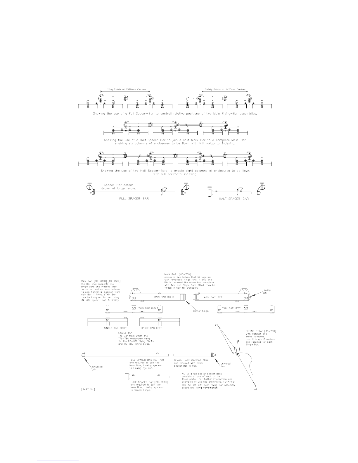
The flying bars consist as follows:
♦
Single bar - supports a vertical column of cabinets up to 5 deep.
♦
Twin bar - supports two single bars.
♦
Main bar - supports two twin bars, and may be lifted by either one motor (for arrays up
to three deep) or two motors for larger systems.
♦
Spacer bars - used to join and maintain the distance between flying bars.
Configurations of these flying bars and spacers can be seen in Figure 3.
Page 9
user manual
TFS-780
TFS-780 user manual
Page 9
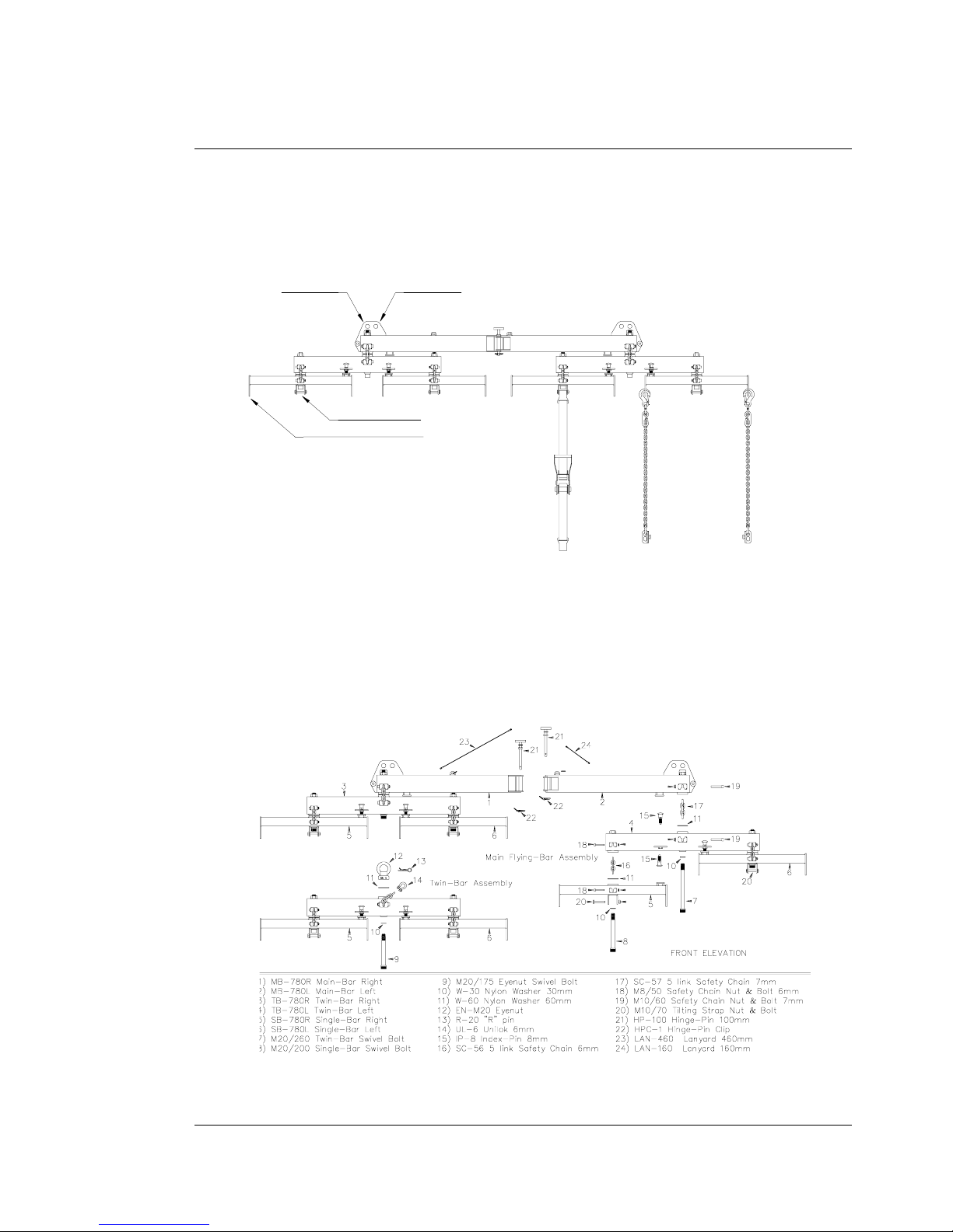
Figure 1. Flying Bar Assembly
Figure 2. Exploded Parts List
Lifting Point Safety P oint
Tilting Strap Point
Flying Chain Suspension Point
To suspend four columns of Flashlight
enclosures with indexed horizontal adjustment.
FC-780 FLYING CHAINS
one pair required
for each enclosure
to be flown.
TS-780 TILTING STRAP
one required
for each column
of enclosures.
(These are handed
left & right, the
left ones have RED
Shortening Hooks,
the right ones BLUE
Shortening Hooks).
FB-780A MAIN BAR
Page 10
user manual
TFS-780
TFS-780 user manual
Page 10
Figure 3. Flying Bars and Spacer Bar Configurations
Figure 4. Flying System Main Components
Page 11
user manual
TFS-780
TFS-780 user manual
Page 11
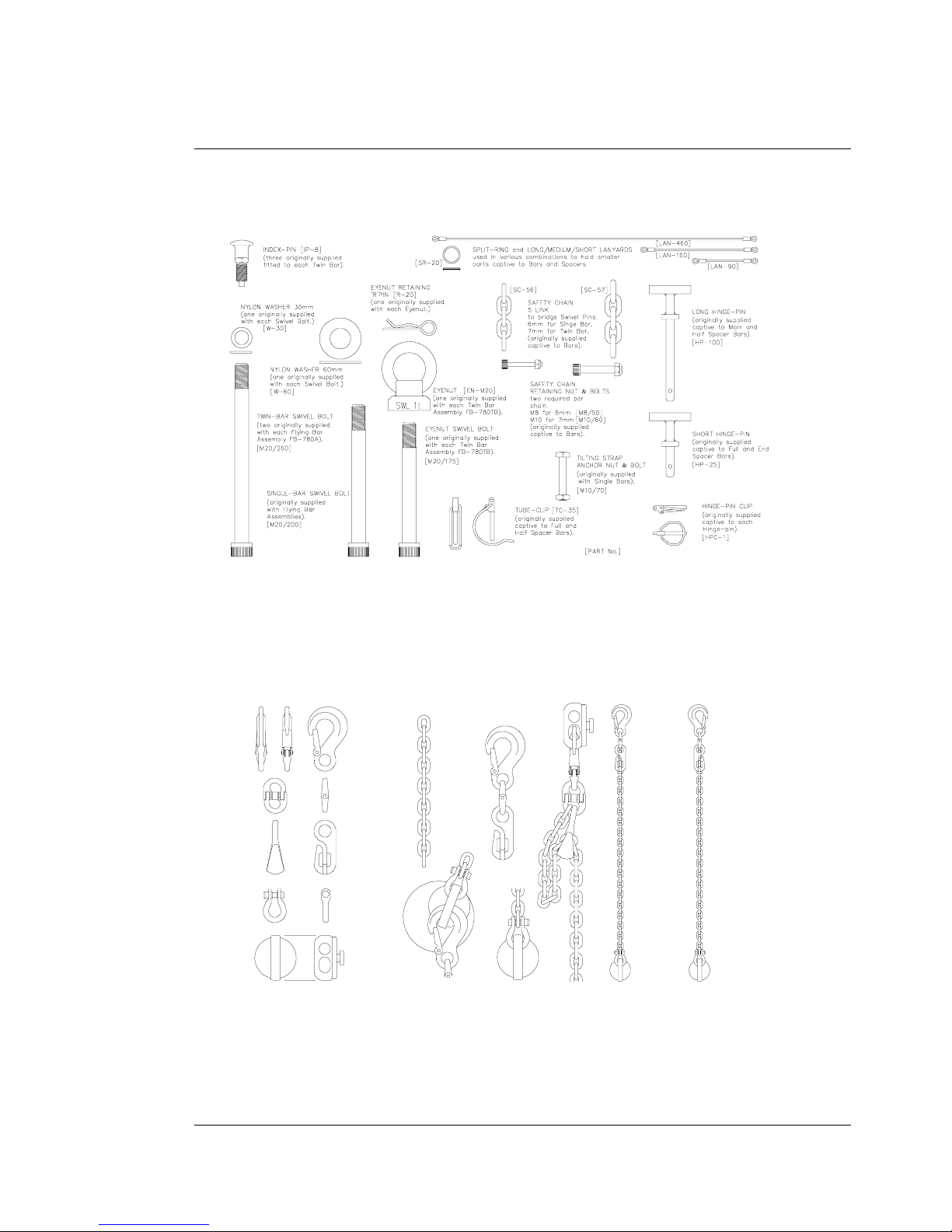
Figure 5. Flying System Small Components
Figure 6. Adjustable Chains
6mm Eye
Safety sling hook
6mm CONNEX
Connecti ng link
6mm
Shortening hook
6mm UNILOCK
'D'-Ring
6mm
Grade 80
Chain
Righthand
Chain (with
blue shortener)
Lefthand
Chain (with
red shortener)
Both Chains are
40 links long
Assembly examples
Page 12
user manual
TFS-780
TFS-780 user manual
Page 12
Setting Horizontal Angles
The Single Bars are pivoted on the Twin Bars which in turn are pivoted on the Main Bar. The
pivots include a nylon spacing washer to eliminate free play and allow for smooth operation.
A spring loaded Index Pin locates in one of a series of holes to secure the pivot at the desired
angle. A particular advantage of this pivot arrangement is that the horizontal splay of the
array may be adjusted whilst the system is in the air, and because the Single and Twin Bars
pivot about their centre points the array remains in perfect balance.
A secondary chain bypasses each pivot point to comply with safety requirements.
The Index Pin allows angles between columns of 0º to 40º to be set in 5º degree increments.
A minimum of 10º in the horizontal plane is recommended between Flashlight high packs to
ensure even coverage at the higher frequencies. Increased coupling is best achieved in the
vertical plane, as described in the next section.
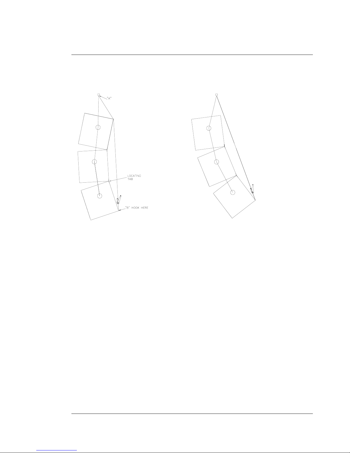
Tilting
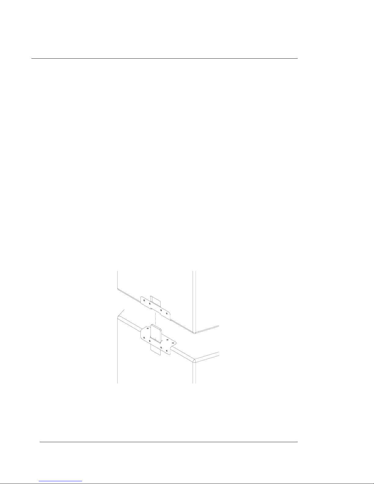
A high density white plastic locating tab
(biscuit)
is secured inside the door of each TFS780H. This is placed in the tilting bar slot at the top rear of the enclosure, and locates in the
enclosure above. These tabs act as simple and efective hinges, and ensure that the backs of
the enclosures stay in alignment with each other.
Page 13
user manual
TFS-780
TFS-780 user manual
Page 13
Figure 7. Tilting Strap Operation
The tilting strap, TS-780, is in two parts. The longer part is attached to the stirrup in the
centre of the flying bar at "A" using the hook at its end. The hook should face towards the
front of the cabinet. The other part of the strap with the ratchet is hooked into the lower slot
of the bottom enclosure at "B". The free end is then threaded through the ratchet and the
strap tightened to achieve the desired tilt.
WARNING
WARNINGWARNING
WARNING
If the strap is released suddenly, the row of enclosures may tend to swing violently forwards
and care must be taken to avoid danger to persons in the vicinity. It is essential to check that
nobody is standing immediately in front of the column, and to give a suitable warning,
before the strap is released. Ideally, two persons should support the row from the side whilst
the strap is released, or alternatively the bottom row may be returned to the ground before
release. In any event it is essential that all personnel in the vicinity are aware that the system
is about to move and that they must keep clear.
Page 14

user manual
TFS-780
TFS-780 user manual
Page 14
The Turbosound TFS-780 system has been designed and constructed to a high standard of
safety and tested to the most demanding of specifications. However, anyone involved in
flying ANY sound system, especially in a touring capacity, should take note of the following
advice:
The rigging of a flown sound system may be dangerous unless undertaken by qualified
The rigging of a flown sound system may be dangerous unless undertaken by qualifiedThe rigging of a flown sound system may be dangerous unless undertaken by qualified
The rigging of a flown sound system may be dangerous unless undertaken by qualified
personnel with the required experience to perform the necessary tasks. Fixing of hanging
personnel with the required experience to perform the necessary tasks. Fixing of hangingpersonnel with the required experience to perform the necessary tasks. Fixing of hanging
personnel with the required experience to perform the necessary tasks. Fixing of hanging
points in a roof should always be carried out by a professional rigger and in accordance with
points in a roof should always be carried out by a professional rigger and in accordance withpoints in a roof should always be carried out by a professional rigger and in accordance with
points in a roof should always be carried out by a professional rigger and in accordance with
the local rules of the venue. The house rigger and/or building manager must always be
the local rules of the venue. The house rigger and/or building manager must always bethe local rules of the venue. The house rigger and/or building manager must always be
the local rules of the venue. The house rigger and/or building manager must always be
consulted.
consulted.consulted.
consulted.
When initially ratcheting a column of speakers it is good to bear in mind the expected angle
of inclination so as to avoid ending up with too much of the strap left on the ratchet. This is
important because the ratchet can only take three complete turns before it releases itself.
It is recommended that you connect the hook to the bottom box, take up the slack in the
strap, and then fit the biscuits working up from the bottom. Initially when the system is hung
and the straps have been tightened just enough for the backs of the cabinets to touch, the
top box should point upwards as shown in Figure 7. When you increase the tension on the
strap the whole column will tilt around the centre of gravity of the column.
The system has been designed around an optimum setting so you must be aware that at
some point the backs of the bottom rows of cabinets will meet and limit any further
adjustment. To stop this you could try one or more of the following:
♦
Reduce the number of rows of cabinets.
♦
Use a smaller amount of horizontal splay.
♦
Use a smaller amount of vertical kelp.
Page 15

user manual
TFS-780
TFS-780 user manual
Page 15
Setting Vertical Angles
Vertical connection between enclosures and to the flying bars is achieved using the Q-D
Flying Plate and D-ring system originally developed for Turbosound's TMS-3 flying systems.
However, instead of fixed-length steel connections, an adjustable length chain is used.
(Figure. 6)
The vertical inter-cabinet angles available are as follows:
Chain
ChainChain
Chain
link in
link inlink in
link in
hook
hookhook
hook
780HF
780HF780HF
780HF
to
toto
to
780HF
780HF780HF
780HF
780HF
780HF780HF
780HF
to
toto
to
780H
780H780H
780H
780H
780H780H
780H
to
toto
to
780H
780H780H
780H
780H
780H 780H
780H
to
toto
to
760H
760H760H
760H
760H
760H760H
760H
to
toto
to
760H
760H760H
760H
Usage
UsageUsage
Usage
0 20º 22º ‡
!
4 3
°
17º 19º ‡
!
5 6
°
14º 14º 28º More
6 9
°
10º 10º 20º Vertical
7 12
°
6º 6º 12º Coverage
8 15
°
4º† 2º† 6º†
!
12 1.5
°
"
13 5
°
Higher Q
14 8
°
More
15 10.5
°
Coupling
16 15
°
"
17 17
°
"
† fit biscuit before chains ‡ greater than maximum length
The top chain from the flybar to the first cabinet can be adjusted to gain more height on the
system and also improve the looks. Alternatively if you are flying four or more cabinets deep
with a lot of kelp it is good to give the top chain some additional length as this makes
racheting easier.
When flying four Flashlight boxes deep the top biscuit can be difficult to fit depending on
how much vertical separation you have on the boxes. However if the top row consists of
bass cabinets where no vertical separation is required then you should use eight links
between the top two rows of cabinets, which requires you to fit the biscuits before fitting the
chains, thus locking the biscuits in place.
Page 16

user manual
TFS-780
TFS-780 user manual
Page 16
Arraying
The concept of arraying the TFS-780 Flashlight system is to create part of the surface of a
sphere. A small part of a large sphere will form a high-directivity
(long-throw)
system with a
high SPL at a distance, whereas a large part of a small sphere will be of lower directivity
producing less SPL at a distance, but having a wider angle of coverage. This approach leads
to the creation of a virtual point source of sound somewhere behind the array.
There are some simple rules to follow to help achieve this goal:
♦
Never point two high packs in exactly the same direction.
♦
Try to obtain a smooth even curve in the horizontal plane.
♦
Use a similar amount of tilt on each column.
♦
Ensure that the bottom corners of each column are in line with each other.
Page 17

user manual
TFS-780
TFS-780 user manual
Page 17
Procedure for flying a Flashlight array
The following notes describe the procedure for flying left and right Flashlight arrays
designed to provide coverage of an outdoor area for approximately 15,000 people. The
configuration in this example is a six-wide Flashlight array, each side of the PA giving a
horizontal coverage angle of about 90°. This is made up of a 4-wide main bar assembly and a
twin bar assembly, requiring three lifting points. A half spacer bar connects the main bar and
twin bar, effectively continuing the curve of the array and setting the distance of the last two
columns, and hence the third lifting point.
1. Remove the flybars from the fly bar trunk
and set them out on the stage wings
according to the required configuration.
Splay all the bars out to form a smooth,
shallow curve by locating the springloaded index pins on each bar in the bar
locator holes. Normally you will want to
start with all the index pins in the fourth
index hole, giving a horizontal splay angle
of 15 degrees between each vertical
column.
2. Move the flybars into the approximate position on the stage wing where the PA is to be
flown, and check that the curve of the array is going give you the expected horizontal
coverage. Position the bars such that the break between the first and second on-stage
columns is pointing directly at the mix position – this works best when the mix position
is between 27.5m (90ft) and 43m (140ft)
from the stage – and make sure that the
off-stage column is giving you adequate
coverage of the bleachers or side-stage
seating. Sometimes you may want to
open up the angle of the two off-stage
columns to the next (fifth) index hole to
give a little more coverage of the offstage seating if it is particularly wide.
Once you are happy with the splay of the
bars, choose and fix your flypoints such that the chain drops fall exactly above, and in
line with, the pick up points on the flybar. Note:
Note: Note:
Note: the outer holes on the flybar are the
pickup points; the inner holes are the safety points. Take time to get the flypoints
positioned accurately, as it is much easier to do it now than later when the flybar is
under load.
Page 18

user manual
TFS-780
TFS-780 user manual
Page 18
3. If space permits, prepare the flown Flashlight high boxes by wheeling them into
position, in two rows six across, behind the flybar position. In this particular
configuration TFS-780HF long-throw mid-high boxes will form the top row of each
column, and for convenience these can be stacked on top of the first row of Flashlights
and wheeled in together. Loosen the camlocks securing the wheelboards to the
underside of the Flashlight cabinets, so that when the cabinets are hoisted the
wheelboards will remain on the ground. Open the access door of each cabinet, take out
the biscuit and allow this to hang outside the box on the captive string. It is better to
leave the EP6 cable inside for now, because once connected later on they should be
stowed inside the box to eliminate any possibility of becoming disconnected.
4. Attach chain motors to the three fly bar
lifting points with shackles and secure
them. Attach safeties if required. The
flybar assembly is now ready be hoisted
to accept the first row of cabinets. Attach
two 1 metre spansets to the cable drop
points on the flybars with shackles to act
as cable strain reliefs. It is a good idea to
have the bulk of the cables tied directly to
the bar as opposed to hanging below it –
in this way their weight is less likely interfere with the column’s centre of gravity. Raise
the flybar to about shoulder height, ensure that it is is level, and once more check the
horizontal coverage. Make any final adjustments to the flypoints now, if required, as the
weight of the flybars is not excessive and it is quite easy to lift the flybar, taking the load
off the chains as they are moved. A couple of inches forward or backwards may make a
significant difference to the way system hangs, so take time to get this right.
5. Attach flying chains to each of the single
bars. The chains are colour coded blue
for left, red for right, looking at the
enclosures from the front. It is a good
idea to count out and hang or lay the
correct number of flying chains out
beforehand in an easily accessible place –
such as on the edge of a fly bar trunk according to their colour: reds together
and blues together. This is a good
opportunity to remove links from the clutch and check their condition. All the hooks
should point outwards from the boxes, with the clutch facing to the front, since this
makes it easier to de-rig later on. This orientation is preferred because if during rigging
or de-rigging the box should come up and into contact with the hook, there is no
Page 19

user manual
TFS-780
TFS-780 user manual
Page 19
possibility of the safety clip being pushed open. Most importantly, all the chain hooks
must face the same way for an even hang.
6. The length of the top row of chains naturally determines the height of the PA, but also
affects the way it looks. A short top chain length results in a neater looking PA, with the
boxes flying closer to the flybars, albeit at the expense of more tension on the tilt strap.
Do this if you want to be able to point the top boxes upwards, i.e. to cover high
balconies. If left long, i.e. completely open, there will be minimum tension on the tilt
straps but the system will not look as neat. Leave the top chains long if you want a large
downward angle on the column. A good compromise and starting point for the top row
is with link number 9 in the clutch. Choosing an odd link number is very desirable
because the chain will automatically hang straight, without the possibility of a 90° twist.
This will also ensure the PA flies fairly close to the flybar. NOTE:
NOTE: NOTE:
NOTE: When on a long tour
and when the PA is flown repeatedly the same way for multiple shows, use tie wraps to
secure links in the shortening clutch to save time.
7. Position the first row of Flashlights,
with the long throw boxes stacked on
top, directly under the flybar assembly.
Open the access door of the long throw
box, fit the biscuit in to the kelping
brackets, and connect the cable. Stow
any excess cable inside the cabinet.
Allow the flying chains to hang freely
down the sides of the boxes. If the Dring does not naturally face the right
way,
do not rotate it
(which will cause a twist in the chain) to force it to face inwards,
simply flip the D-ring over so that it points in towards the fly point. NOTE:
NOTE: NOTE:
NOTE: later flying
chains, shipped after September 2000, are re-designed with two separate apertures in
the D-ring so that it cannot accidentally flip over; in this case simply allow the the chain
to hang freely and then rotate a quarter turn clockwise or counter-clockwise as
appropriate to point in towards the box. Snap the D-rings into the flyplates on the
cabinets by inserting and lifting sharply until you hear a solid click.
8. Attach the long part of the tilting straps
to the stirrup at the centre of each
single flybar, with the hook facing
forwards. Rather than letting the tilt
straps hang at the back of each box, it is
better to gather three to one side and
three to the other, to hang down at the
sides of the array until it is time to kelp
the boxes. This will avoid uneccessary
Page 20

user manual
TFS-780
TFS-780 user manual
Page 20
clutter when fitting biscuits and cables on subsequent rows of boxes.
9. Snap on the next row of flying chains, hooks facing forward, again observing the colour
coding – red for right, blue for left. The length of the flying chain will determine the
vertical angle between the first row and the second row of boxes. You will want the first
row of Flashlights to couple with the long throw boxes on the top row, so place link #27
in the clutch. This will result in a vertical angle of 3.5º between boxes.
10. Raise the PA about a further metre to
allow the third row of Flashlights to be
wheeled in underneath, having first
loosened the camlocks on the
wheelboards. Snap in a third row of
flying chains, again observing the colour
code. Shorten the chains by placing link
#7 in the clutch, which will result in a
vertical angle of 5° between boxes.
11. Raise the PA another metre or so, and
position downfill boxes face down on the
ground, or face down on a Flashlight
wheel board and roll into place
immediately below each column. There
are two types of downfill, a low-mid
(identified by the EP6 connector) and a
high-mid (identified by the XLR
connector). It is common to ‘chequerboard’ the downfills so that you end up
with a high-mid, low-mid, high-mid, low-mid, high-mid, low-mid arrangement left to
right across the PA. However there is often an exaggerated coupling of low-mid energy
from the PA and coming from the stage which, combined with the wider dispersion
created at lower mid frequencies, is sometimes undesirable. In this case try using all
high-mid downfills on the bottom row instead to clean up these frequencies close to the
stage.
12. Shorten each chain by placing link #10 in
the clutch and snap the D-rings into the
flyplates on the downfill boxes. Open the
access door, and take out the tilting strap.
The downfills are angled independently of
the main part of the array by means of
their own tilt straps, which are simply
Page 21

user manual
TFS-780
TFS-780 user manual
Page 21
secured to the Flashlight box above. Angle the downfills so that the top side is parallel to
the bottom of the cabinet above it. The exact angle will work out to be between 30° and
34° from the Flashlight box above it. For most applications this will give you the
optimum front fill coverage.
13. Attach a ratchet to the bottom kelping bracket on the lowest Flashlight box and feed the
free end of the tilting strap through the slot in the centre of the ratchet spindle. Place the
biscuits into the kelping bracket at the top of each box, and as you gradually pull
upwards on the strap guide the box above to allow the biscuit to settle into its lower
kelping bracket. The lower boxes will close up first as you continue to increase tension
on the tilt strap. When flying an array
with more than three Flashlight boxes
deep it is preferable that this procedure
be carried by two people, with one
person standing on a speaker box or
similar to be able to locate the highest
biscuit. When all the biscuits in the
column have positively located in the
kelping brackets, give the tilt strap one
more pull before beginning to ratchet
the column. If you leave too much slack at the free end of the strap the ratchet will not
be able to accommodate more than 2 or 3 layers of webbing without disabling the clutch
mechanism. At this stage do not put a lot of angle on the column, as it is much easier to
increase the amount of kelp than to decrease it. When using a chain length shorter than
link number seven in the clutch, a Flashlight box will naturally tend to hang pointing
slightly upwards, making the fitting of the biscuits very easy. However, if a shorter chain
is used (i.e. link number 8) you must fit the biscuit between boxes before attaching
chains to the lower box
.
14. Check the tilt of the boxes now with an inclinometer. Gradually ratchet the column until
you have achieved the required downward angle of the PA. Repeat for the remaining
columns.
Page 22

user manual
TFS-780
TFS-780 user manual
Page 22
15. Attach the end of a long tape measure to the back corner of the lowest onstage
Flashlight cabinet. Raise the PA and note the exact height above the stage so that you
can mirror this vertical position to the other cluster. This will ensure that the both left
and right PA clusters are level.
16. When the flown arrays are in position, wheel in the Flashlight bass enclosures, and stack
them on the stage wings in three columns each of six cabinets. All the boxes are placed
on their sides, and mutual coupling is acheived by placing them ‘door to door’ so
forming a larger horn mouth. The two off-stage columns are stacked, with sides
touching and facing perpendicular to the stage edge, while the on-stage column is
angled inwards several degrees to point directly towards the mix position.
Page 23

user manual
TFS-780
TFS-780 user manual
Page 23
Bass Enclosure arraying
Flashlight bass enclosures are most efficient when ground stacked in a block. Not only do
they benefit from improved coupling when there are no air gaps between them, but they also
couple to the ground. However, some of this energy may be absorbed by nearby
obstructions such as barriers or a tightly-packed standing audience. Sound pressure levels
may also be excessive for members of the audience if they are able to get too close to the
enclosures. When stacking on the stage or on a platform, particularly outdoors, it is
preferable to close the gap between the platform and the floor with sheets of plywood. This
results in increased sound projection into the audience and less leakage backstage.
Aiming - directivity of the stack
The directivity of the bass stack will depend on its dimensions and curvature. A tall thin stack
will disperse a lot in the horizontal plane and become narrow in the vertical plane and
likewise a wide stack will narrow in the horizontal plane. There is usually an optimum
compromise between the two so that a smooth transition can be obtained between the effect
of the coupling of the two stacks down the centre line of the room and the effect of the
individual stacks beaming on their axis. Also adding some curvature to the stack will help to
increase the directivity of the stack especially in the higher frequencies.
Turbosound Flashlight bass bins can be stacked in various configurations, each giving a
certain emphasis which can be used to great advantage dependent on the room, situation
and type of music.
Stacking in pairs mouth to mouth (access panels outwards) helps the bins to couple giving a
wider mouth area and lower bass response. The example shown below will result in a strong
punchy low end partly due to the floor coupling. This configuration works well for rock
music, giving a solid low end. Stack two bass bins on their ends, with a Floodlight front fill
on top, between two columns of 4 high, 2 wide bass enclosures. Place the onstage columns
flush and parallel with the stage front, turning the offstage colum out towards the side.
Page 24

user manual
TFS-780
TFS-780 user manual
Page 24
An alternate arrangement is to stack the bass enclosures with a curve similar to the flown
array above it, giving a strong, punchy low end with even dispersion. The first row are
stacked door to the floor, with remaining bins alternately inverted in rows six across and
three high. The bass stack should be placed slightly apart from the stage, with the inside
column pointing directly at the mix position. The remaining columns are splayed evenly with
a 6” to 8” gap between each column. This arrangement works well for house and dance
music. A TFL-760HM placed on the stage edge gives excellent front fill coverage.
Tall, thin bass stacks work best, preferably in blocks of eight bins high by two wide. When
space permits use two of these blocks, the onstage block flush with and parallel to the stage,
with a second identical offstage block slightly separated from the first and angled outwards
by 10°.
Page 25

user manual
TFS-780
TFS-780 user manual
Page 25
STAGE
Ground stacking
In certain situations, indoors or outdoors, it may not be possible to fly any part of the system.
In this case, the same general rules apply as for flown arrays. High packs should be kept well
above head-height and angled carefully for even coverage. Small wood blocks may be used
to tilt cabinets upward for raised audience areas and downward for the floor areas, with the
locating biscuits being used for stability. Suitable wood blocks should always be carried for
this purpose.
In general, the wider dispersion Floodlight enclosures should be used for close range ground
stacked applications, i.e. to cover the nearest audience areas. Flashlight enclosures may be
used to cover the more distant areas from positions at the top of the stacks, where their high
Q (narrow dispersion) is ideal for
long throw
applications. Flashlight should not be stacked
directly on top of Floodlight as this arrangement is potentially unstable due to the difference
in cabinet sizes and centres of gravity.
Vertical Dispersion Considerations
Tightly coupling a pair of cabinets with the upper one inverted
to place the HF drivers close together will result in reduced
vertical dispersion and a higher level on axis which can improve
the projection in long throw situations, but this orientation is
normally unsatisfactory with Flashlight due to the asymmetric
nature of the cabinet. However experimentation with Floodlight
can produce acceptable results although a general degradation
in performance may be apparent. When stacking cabinets on top
of each other the right way up you should use a spacer in
between the fronts of each cabinet to introduce some vertical
angle in the stack. Care should be taken to ensure that the stack
remains stable and using the biscuit slots will help to prevent
cabinets from sliding around.
Page 26

user manual
TFS-780
TFS-780 user manual
Page 26
Flown Systems
For Flashlight in
short throw
use, the smoothest vertical dispersion is achieved with an
intercabinet angle of around 10° (with both cabinets the same way up). Reducing this angle
reduces vertical dispersion (increases the projection) but results in a less smooth dispersion
pattern. As these deviations in the vertical coverage are not normally perceptible to the
audience, smaller vertical cabinet angles may be safely selected to suit the projection or
throw
required. Angles greater than 15° will however result in a loss of coverage on axis and
should be avoided.
In most applications the upper rows of a cluster of cabinets will cover the more distant
sections of the audience, and the vertical intercabinet angles will therefore be progressively
smaller towards the top of the cluster.
Vertical: 10 degrees
between cabinets
Horizontal: 15 degrees
between columns
Page 27

user manual
TFS-780
TFS-780 user manual
Page 27
LMS-D6 LOUDSPEAKER MANAGEMENT SYSTEM
Introduction
This section is provided with the aim of assisting sound engineers, installers and consultants
to fully understand the LMS-D6, and to obtain the full benefit of its capabilities.
The LMS-D6 is a dedicated Loudspeaker Management System, specially configured for
Turbosound's Flashlight & Floodlight Systems, and to be used in conjunction with
Turbosound AMP-780 amplifier racks.
General features & facilities
Unpacking
As part of Turbosound's system of quality control, this product is carefully checked before
packing, to ensure flawless appearance. After unpacking the unit, please inspect for any
physical damage and retain the shipping carton and all relevant packing materials for use
should the unit need returning.
After unpacking the unit please check carefully for damage. If damage is found, please notify
the carrier concerned at once. You, the consignee, must instigate any claim. Please retain all
packaging in case of future re-shipment.
There will be a small packet of spare fuses with the unit. Please keep them in a safe place.
If any damage has occurred, please notify your dealer immediately, so that a written claim
for damages can be initiated. See the Warranty section at the end of this manual.
Mechanical Installation
A vertical rack space of 1U (44mm / 1.75") is required for each unit. If used in a mobile or
transportable system, the unit must be supported at the rear by additional bracing or
shelving, to prevent vibration-induced metal fatigue of the racking ‘ears’. Failure to do this
will impair reliability and invalidate the Warranty. The rack casing will need a depth of
425mm (minimum) to clear the connectors.
Adequate ventilation must be provided by allowing sufficient room around the sides and rear
of the unit to permit free circulation of air. Forced cooling is not required, a factor which aids
component longevity. The front of the unit should not be exposed to long term direct
sunlight as this can have a detrimental effect on the display lens.
Page 28

user manual
TFS-780
TFS-780 user manual
Page 28
LMS-D6 Front Panel Functions
1. LCD Display
LCD Display LCD Display
LCD Display - Shows menu options, output information and parameters being adjusted.
2. Gain Keys
Gain KeysGain Keys
Gain Keys - Two input and six-output ‘gain’ keys allow instant access to the gain screen for
each channel. Pressing a second time selects the last function edited.
3. Next Key
Next KeyNext Key
Next Key - Moves the display forwards through the list of available parameters for the
current input or output channel.
4. Back Key
Back KeyBack Key
Back Key - Moves the display backwards through the list of available parameters for the
current input or output channel.
5. Menu Key
Menu KeyMenu Key
Menu Key - Activates the main menu on the LCD display. Pressing a second time selects the
last menu edited. Different menus are selected by pressing the
‘BACK’
and
‘NEXT’
keys or
using the
‘FREQ’
control.
6. Enter Key
Enter KeyEnter Key
Enter Key - Enters the chosen menu and confirms menu selections.
7. OUT Key
OUT KeyOUT Key
OUT Key - Exits the menu.
8. Bypass Key
Bypass KeyBypass Key
Bypass Key - Allows the currently displayed parametric section to be bypassed. (Note: The
Highpass / Lowpass filters and limiters can not be bypassed.)
9. Parameter Controls
Parameter ControlsParameter Controls
Parameter Controls - The three velocity sensitive rotary encoders allow the relevant
parameter, on the LCD screen, to be adjusted.
10. Input Meters
Input MetersInput Meters
Input Meters - Displays available headroom before input clipping occurs. The bottom green
LED is set at -24dB, with the orange 0dB LED set at 3dB below clipping. The top, red LED
displays digital overflow and can therefore light without all the other LEDs becoming
illuminated.
11. Output Meters
Output MetersOutput Meters
Output Meters - Displays headroom before limiting occurs. The bottom green LED is set at 24dB, with the orange ‘LIM’ LED set at the limiter threshold for that channel. The top, red
LED indicates 4dB of limiting.
12. Mute Keys
Mute KeysMute Keys
Mute Keys – One mute key per output channel.
5 4 3 6 9 10 11 12
1 8 7 2
'Q'
3
LIM
-3
-24
LIM
-3
-24
LIM
-3
-24
MENU
BYPASS
ENTER
OUT
FREQ 'Q' GAIN
CLIP
-6
-24
GAIN GAIN GAIN GAIN GAIN GAIN GAIN GAIN
MUTE MUTE MUTE
AB 12 456
DIGITAL LOUDSPEAKER MANAGEMENT SYSTEM
LMS-D6
LIM
-3
-24
LIM
-3
-24
TQ-440
Page 29

user manual
TFS-780
TFS-780 user manual
Page 29
LMS-D6 Rear Panel Functions
1. Power Switch
Power SwitchPower Switch
Power Switch.
2. Mains Fuse
Mains FuseMains Fuse
Mains Fuse - Located in a finger-proof fuseholder adjacent to the mains inlet. Always
replace this fuse with the correct type as shown on the rear panel legend. (N.B. A spare
fuse is located in this holder.)
3. Mains Power
Mains PowerMains Power
Mains Power - Connected via a standard IEC socket. A compatible power cord is
supplied with the unit.
4. External
ExternalExternal
External - RS232 via a 9-pin DIN DEE socket, for connection to a PC.
5. XLR Inputs and Outputs
XLR Inputs and OutputsXLR Inputs and Outputs
XLR Inputs and Outputs - 3 pin XLR connectors are provided for each audio input and
output. All terminations are fully balanced, pin 2 Hot, pin 3 Cold and pin 1 not connected.
Mains Power
The LMS-D6 must always be connected to a 3 wire grounded AC supply. It is supplied with a
standard IEC power cord with conductors as follows:
BROWN Power line Live (Phase)
BLUE Power line Neutral
GREEN/YELLOW Safety Earth and ground connection
Units supplied to the North American market are fitted with an integral moulded 3 pin
connector, which is provided to satisfy UL & CSA safety standards.
1 2 3 4 5
INPUT B INPUT A
CUSTOM MAD E FOR TURBOSOUND
IN THE UK BY XTA ELECTRONICS
PROTECTION AGAINST FIRE
REPLACE ONLY WITH THE
SAME TYPE T1A, 250V FUSE
RS232
DATA IN PUT
PIN1=SHIELD
PIN2=H OT
PIN3=COLD
THIS EQUIPMENT MUST BE EARTHED
RISQUE DE CHOC E LECT RIQUE - NE PAS OUVR IR
WARNING / AVIS
OUTPUT 6 OUTPUT 5 OUTPUT 4 OUTPUT 3 OUTPUT 2 OUTPUT 1
DO NOT EXPOSE TO RAIN OR MOISTURE
SHOCK HAZARD – DO N OT REMO VE COVERS
Page 30

user manual
TFS-780
TFS-780 user manual
Page 30
Voltage Setting
The LMS-D6 is provided with an auto-seeking power supply, and therefore requires no
external adjustment for correct operation with international AC line voltages ranging from 60
to 250 volts.
Safety Earthing
The green/yellow wire of mains cord must always be connected to the electrical installation's
Safety Earth or Ground. It is essential for personal safety, as well as proper operation of the
unit.
The green/yellow wire is internally connected to all exposed metal surfaces. Any rack
framework which this unit might be mounted into is assumed to be connected to the same
grounding circuit. The LMS-D6 has balanced audio connections and does not require
disconnection of this or any other safety earth for the avoidance of hum loops. If any
problems are experienced with hums or buzzes, careful attention to the signal cable
grounding will effect a cure.
AC Power Fusing
The incoming mains power fuseholder is mounted on the rear panel. If the fuse needs to be
replaced it must be properly rated as follows: 20mm 1A 250 V type T. It is important for
continued safety that this specification is adhered to. It is very unlikely that this fuse will fail
during normal use, and such a situation must be treated with some caution as to the cause.
Powering Up
When the LMS-D6 is switched on by operating the power on-off switch located on the rear
panel, the internal circuitry carries out a series of routine diagnostic tests.
After the switch-on cycle, the screen will revert to displaying the delay program name that
was in use when the unit was last powered down.
The internal memory automatically saves all settings when the unit is switched off, so there
is no need to re-load delay and temperature information every time the system is poweredup. The memory contents are retained indefinitely without the need for an internal backup
battery.
Page 31

user manual
TFS-780
TFS-780 user manual
Page 31
Audio Connections
The LMS-D6 audio inputs are RFI filtered and electronically balanced. The outputs are
electronically balanced and fully floating. Overall, the unit is designed to operate at any
signal levels ranging -10dBu up to +20dBu. The outputs will drive into loads of 600 Ohms or
greater and both inputs and outputs are intended to be 'fuss free', regardless of an
installation's complexity.
The connector wiring is as follows:
Input Output
Pin 1 n/c Pin 1 n/c
Pin 2 hot (+) Pin 2 hot (+)
Pin 3 cold (-) Pin 3 cold (-)
Input and Output Connector Wiring
Balanced Wiring
Whether a system is wired to a 'pin 3 hot' or a 'pin 2 hot' convention will not matter as long
as the wiring of hot & cold phases to both the input and output XLR connectors is the same.
At the LMS-D6 input, the convention is 'screen goes forward with the signal'. Input cable
screening therefore needs to be connected at and derived from the signal source end, as pin
1 on the input XLR is not connected to the LMS-D6 chassis nor signal ground.
Time correction for loudspeaker driver placement
When a loudspeaker sound system is constructed which utilises different loudspeaker drivers
for separate frequency bands, it is inevitable that the sound sources are non-coincident. The
effect of this is that phase and time differences occur, producing a substantial cancellation of
the signal around the crossover region. There is also a general lack of transient clarity or
smearing
of the sound, resulting from an inaccurate combining of the wavefront. The LMSD6 provides and maintains the optimum signal delay between the HF and HMF drivers and
the LMF driver in the TFS-780H when the unit is switched to Flashlight mode, and in
Floodlight mode the three drivers in the TFL-760H are physically aligned so inter-driver time
delays are switched out.
Page 32
user manual
TFS-780
TFS-780 user manual
Page 32
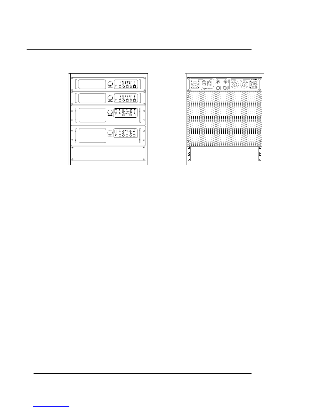
AMP-780.2 FLASHLIGHT SYSTEM AMPLIFICATION RACK
Racking, Cables and Connections
The AMP-780.2 Flashlight amplification system comprises a complete amplifier rack,
flightcase and cabling system which can power the recommended system configuration of
six TFS-780H and six TFS-780L, although each rack is capable of powering up to eight TFS780H and eight TFS-780L enclosures if required.
The rack contains TMC series amplifiers designed and developed in England for Turbosound
by MC
2
Audio Ltd.
Input and output connectors are mounted on a single 2U 19" panel at the rear of the rack.
The amplifier rack is supplied with the facility to monitor and control certain amplifier
functions remotely via a simple 2-wire connection using the loop-in and loop-out XLR
connectors provided on the rear panel to a laptop or desktop computer.
The rack itself is a space frame, fabricated from rectangular steel sections with all necessary
mounting points welded in. The top and side apertures are fitted with panels which may be
supplied in a variety of different finishes to blend with any particular packaging. These are
secured with Velcro to allow easy access to the amplifiers and cabling.
A fully shock mounted road case with four heavy duty castors completes the system, which
is designed to fit four across in a standard width truck.
ΡΕΜΟΤΕ ΧΟΝΤΡΟΛ ∆ΑΤΑ
ΒΟΤΗ ΧΗΑΝΝΕΛΣ.
ΙΝΠΥΤ
ΑΝ∆
ΛΙΝΚ
ΛΟΩ ΟΥ ΤΠΥΤΣ
ΙΝΠΥΤ
ΟΡ
ΛΙΝΚ
ΣΙΓΝΑΛ
ΗΙΓΗ ΟΥΤΠΥΤΣ
ΑΜΠ−780.2
Page 33

user manual
TFS-780
TFS-780 user manual
Page 33
Options
The rack is supplied fitted with four amplifiers as standard. The two top amplifiers are TMC750 models, and power the high frequency and high-mid frequency sections respectively,
while the two bottom amplifiers are TMC-1250 models and power the low-mid frequency and
low frequency sections respectively. Separate adjustment of the levels of left and right sides
of the rack is possible on all frequency bands. Furthermore, the rack may be operated in twochannel or stereo mode by removal of the link plug (dongle) located under the top panel.
Input Connections
As will be seen from the wiring schedule below, the incoming 11 pin Lemo socket is
connected via the mono/stereo linking connector to the adjacent link-out Lemo and to the
XLR male cable plugs which connect LF, LMF, HMF and HF feeds to the amplifiers in the rack.
In two-channel mode, the second Lemo socket becomes the input connector for the second
channel.
Figure 1. Amplifier Rack Signal Wiring
Page 34

user manual
TFS-780
TFS-780 user manual
Page 34
Output Connections
The amplifier outputs are wired to two 19-way CEEP (Socapex compatible) output sockets,
rated at 20 Amperes per contact, which drive the TFS-780L and TFS-780H respectively.
The output wiring has been arranged to preclude accidental connection of the LF output to
anything other than the TFS-780L, preventing any risk of drive-unit damage.
Mated connectors are screw-locked, ensuring reliability.
In addition, there are two EP6 and two XLR outputs for running small systems not requiring
multicore loudspeaker extension cables.
Two 4 metre fanouts are supplied to take the 19-way cable outputs to the speakers. The Low
fanout is fitted with six female XLR connectors and the High fanout with four EP6 connectors.
The cables are labelled to indicate which amplifier channels they relate to.
Remote Control Connections
Two 3-pin XLR connectors are provided on the rear to enable the external remote control and
monitoring of certain amplifier functions such as power on/off, temperature and gain. All that
is required to enable this facility is a 2-wire connection via a RS232 to RS485 adapter to a
laptop or desktop computer. The software is supplied free of charge as a download from the
Turbosound web site at www.turbosound.com. The remote control facility is able to maintain
control of a virtually unlimited number of amplifiers, and can group amplifiers or amplifier
racks into zones if required.
Page 35

user manual
TFS-780
TFS-780 user manual
Page 35
Extension Cables
19-way extension cables are available to order in 25, 50 and 100 metre lengths (EX-780) for
flying and/or remote positioning of amplifier racks. These cables utilise 2.5 mm
2
conductors
for low line resistance and are black in colour to minimise visibility to the audience.
Figure 2. Multiway Outputs.
Figure 3. Auxiliary Outputs.
Page 36

user manual
TFS-780
TFS-780 user manual
Page 36
Figure 4. Multiway to EP6 Fan-Out.
Figure 5. Multiway Cables.
Mains Connections
Incoming mains power may be connected by one of a variety of
C Form
connectors,
depending on the power system specified when the rack was ordered. Typical supply
configurations are as follows:
110 V star-wired (3 phase) 110 V parallel (1 phase)
220/240 V (3 phase) 220/240 V (1 phase)
The mains power wiring utilises Wago distribution blocks with spring-loaded screwless
connectors. The power wiring may therefore be quickly and easily reconfigured should the
need arise, for example if conversion from single to three phase operation is required. We
recommend you consult a qualified electrician in cases of uncertainty.
Page 37

user manual
TFS-780
TFS-780 user manual
Page 37
TMC-750 AND TMC-1250 HIGH EFFICIENCY AUDIO POWER AMPLIFIERS
General Features & Facilities
The TMC-750 and TMC-1250 are highly efficient, rugged high power amplifiers, with many
original features developed to meet the requirements of modern professional sound
reinforcement, for both touring and fixed installations. They have been designed with audio
quality ranking equal first alongside utility and ruggedness.
♦
Two independently controlled and powered channels.
♦
High continuous power, in excess of 750 watts per channel into 4 ohms (TMC-750) and
1250 watts per channel into 4 ohms (TMC-1250).
♦
A 10kΩ actively balanced, fully floating input is fitted as standard.
♦
Bargraph meter display of output headroom.
♦
LED display of output device temperature.
♦
High damping factor, >400 below 1kHz.
♦
Complementary class AB bipolar outputs, with unique floating drive stage for optimum
audio performance.
♦
Sophisticated monitoring of load and temperature.
♦
Low noise vari-speed fans for quiet operation.
♦
User selectable clip limiter with ‘tight’ and ‘easy’ settings which track the supply voltage.
♦
Front-panel accessible filter for improved dust collection.
♦
Fully functional bi-directional remote control via RS485.
♦
Consistent reliability and easy serviceability through solid, lightweight construction and
modular packaging.
Page 38

user manual
TFS-780
TFS-780 user manual
Page 38
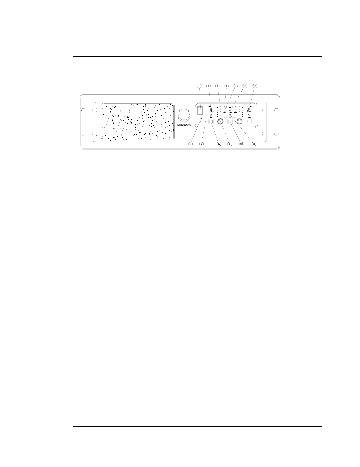
Front Panel Functions TMC-750
1. Mains power rocker switch
Mains power rocker switchMains power rocker switch
Mains power rocker switch – applies AC mains power to the amplifier.
2. Mains power LED
Mains power LED Mains power LED
Mains power LED – illuminates when AC power is applied to the amplifier.
3. Low impedance 2 Ohm LED
Low impedance 2 Ohm LED Low impedance 2 Ohm LED
Low impedance 2 Ohm LED – indicates when the 2 Ohm load setting is selected.
4. Mute LED
Mute LED Mute LED
Mute LED – illuminates when the channel is muted.
5. Mute switch
Mute switch Mute switch
Mute switch – disconnects the output of the relevant channel from the loudspeaker
load.
6. Gain
Gain Gain
Gain – rotary encoder which allows the gain of the channel to be adjusted.
7. LED ladder
LED ladder LED ladder
LED ladder – displays that channel’s output drive level. The bottom (green) LED is set at
–25dB, and the top (red) LED is set at 0.25dB below true clip level.
8. Limit LED
Limit LED Limit LED
Limit LED – illuminates when the channel is clipping.
9. Fault LED
Fault LED Fault LED
Fault LED – indicates when the DC and/or short circuit protection has been activated.
10. Link switch
Link switch Link switch
Link switch – connects the inputs of channel A and channel B together.
11. Link LED
Link LED Link LED
Link LED – illuminates when channels a and B are linked.
12. Temp LED
Temp LED Temp LED
Temp LED – illuminates when the temperature of the output devices exceeds 90° C. At
the sme time the channel output will be reduced by 3dB.
13.
Bridged LED –
Bridged LED – Bridged LED –
Bridged LED – indicates when the amplifier bridged mode is selected.
Page 39
user manual
TFS-780
TFS-780 user manual
Page 39
Front Panel Functions TMC-1250
1. Mains power rocker switch
Mains power rocker switchMains power rocker switch
Mains power rocker switch – applies AC mains power to the amplifier.
2. Mains power LED
Mains power LED Mains power LED
Mains power LED – illuminates when AC power is applied to the amplifier.
3. Low impedance 2 Ohm LED
Low impedance 2 Ohm LED Low impedance 2 Ohm LED
Low impedance 2 Ohm LED – indicates when the 2 Ohm load setting is selected.
4. Mute LED
Mute LED Mute LED
Mute LED – illuminates when the channel is muted.
5. Mute switch
Mute switch Mute switch
Mute switch – disconnects the output of the relevant channel from the loudspeaker load.
6. Gain
Gain Gain
Gain – rotary encoder which allows the gain of the channel to be adjusted.
7. LED ladder
LED ladder LED ladder
LED ladder – displays that channel’s output drive level. The bottom (green) LED is set at
–25dB, and the top (red) LED is set at 0.25dB below true clip level.
8. Limit LED
Limit LED Limit LED
Limit LED – illuminates when the channel is clipping.
9. Fault LED
Fault LED Fault LED
Fault LED – indicates when the DC and/or short circuit protection has been activated.
10. Link switch
Link switch Link switch
Link switch – connects the inputs of channel A and channel B together.
11. Link LED
Link LED Link LED
Link LED – illuminates when channels a and B are linked.
12. Temp LED
Temp LED Temp LED
Temp LED – illuminates when the temperature of the output devices exceeds 90° C. At
the sme time the channel output will be reduced by 3dB.
13. Bridged LED
Bridged LEDBridged LED
Bridged LED – indicates when the amplifier bridged mode is selected.
O
I
Page 40

user manual
TFS-780
TFS-780 user manual
Page 40
Remote
Input Output
Fuse 10 Amp Anti-surge
Bridged
WARNING
Replace fuse with same
Do not expose this unit
Stereo
Channel AInputOutput Channel B
Pin.2.
Pin 3
Pin 2
Pin 3
+
-
+
_
+
_
+
_
2/4
4/8
Link Link
o
a
d
L
ohms
ohms
Volts.AC
Pin 1 GND. Pin 1 GND.
Made in EnglandMC 2Audio Ltd
This unit must be earthed.
Shock hazard - do not
to moisture.
type only.
remove covers.
(mono)
Serial No.
2(4)
+
-
Reset
B
230VAc
OUTPUT
+
-
Channel B
LINKED INPUTS
MC AUDIO LTD
2
Do not expose this unit to moisture.
Shock hazard - do not remove covers.
This unit must be earthed.
WARNING
MADE IN ENGLAND
LINKED INPUTS
Channel A
bridged mode, value in brackets ().
NOTE: Impedanc es double in
ohms
4(8)
ohms
Bridged
(mono)
Stereo
O
A
D
L
+
A
Remote
OUTPUT
+
-
Rear Panel Functions
1. Loudspeaker terminals
Loudspeaker terminals Loudspeaker terminals
Loudspeaker terminals – 4mm banana terminals for connection to the loudspeaker.
2. XLR inputs
XLR inputs XLR inputs
XLR inputs – 3 pin XLR connectors are provided for input and link connections.
3. Stereo/bridged (mono) switch
Stereo/bridged (mono) switchStereo/bridged (mono) switch
Stereo/bridged (mono) switch – allows the amplifier to be operated in bridged mode.
4. Load impedance switch
Load impedance switch Load impedance switch
Load impedance switch – switches between 4 Ohm and 2 Ohm operation.
5. Remote control connector
Remote control connector Remote control connector
Remote control connector – monitor and control amplifier functions via RS485 port.
6. Fuse (TMC-750) or Reset button (TMC-1250)
Fuse (TMC-750) or Reset button (TMC-1250)Fuse (TMC-750) or Reset button (TMC-1250)
Fuse (TMC-750) or Reset button (TMC-1250)
Page 41

user manual
TFS-780
TFS-780 user manual
Page 41
Mechanical Installation
When supplied as part of the AMP-780.2 system rack, the amplifiers are pre-installed. If an
amplifier is removed from the rack for any reason, it is important to re-install it correctly. The
amplifiers must be supported at the front and rear, as originally supplied. Failure to support
it adequately may eventually result in vibration-induced metal fatigue of the rack mounting
ears and such damage will not be covered by the warranty.
Adequate ventilation is essential, both at the rear of the rack, the sides, and also at the front.
This should be considered carefully when placing covers around the racks for protection
from inclement weather at outdoor events, or when using blacks to mask them from view. If
the venting is inadequate, the amplifier's temperature metering will display this.
CAUTION
CAUTIONCAUTION
CAUTION: Air emerging from the amplifier's high efficiency heat-exchangers can reach 60°C
to 70°C. To prevent personal injury or fire, please ensure that people and combustible or
flammable materials (e.g. plastic waterproofing, newspaper, clothing, costumes, solvents)
are kept at least 2'/0.6m from the amplifier's exhaust outlets. If venting is inadequate, the hot
air can adversely affect other equipment, and may soften some thermoplastic enclosures. If
using plastic coated cables, take care to dress the leads away from the airflow. Professionalgrade rubber cables are not affected.
Mains Power
The TMC amplifiers will operate from any international 50 - 60Hz AC mains supply between
110-120 V and 220-240 V. Separate models are supplied to match local mains supply
requirements.
Powering Up
When the amplifier is switched on by depressing the black POWER rocker switch, four or five
LED’s will briefly light up. The POWER LED will remain illuminated.
The amplifier’s microprocessor checks internal voltages before connecting the ouptut stages.
This start-up phase lasts for only a few seconds, after which the output drive ramps up to its
previously selected level, dependent on the input rotary encoder settings. The pause allows
you time to (re) mute the channels to silence the outputs if desired.
Page 42

user manual
TFS-780
TFS-780 user manual
Page 42
Safety Earthing
The Green/Yellow wire on the TMC-750 and TMC-1250’s mains cord must always be
connected to the electrical installation's safety Earth (or Ground). It is essential for personal
safety. The rack framework is connected to the same grounding circuit.
Internal Fuses
The fuses are as follows:
Mains: 10A, 20mm; type H. DC rails: 2 x 250mA, 20mm 3.15mA anti-surge
Should one or more fuses blow, make a single replacement after checking for and
eliminating any obvious causes. If the replacement fuse should blow, please contact your
local dealer for service.
It is most important that all fuses are replaced with the correct specified type, i.e. equivalent
to those supplied.
Voltage Setting
Your models will be set up at the factory for correct operation on your local voltage supply.
No further adjustment is necessary.
Voltage Range
The minimum supply voltage over which the amplifier will operate is 180V for the 220-240V
range, and 90V for the 110-120V range. Naturally, maximum power output will be reduced
accordingly from the published ratings.
The maximum supply voltage which exceeds safe limits and causes the amplifiers to switchoff is in excess of 260 V for 220/240 V range, and 130 V for the 108/120 V range. This is
however dependent on load impedance and program drive level as mentioned above.
Obviously, the mains voltage will reach these limits only in exceptional circumstances and
the FAULT LED will then flash.
Current Consumption
The full drive current requirements are: (True rms Amperes)
nominal 240V supplies
nominal 240V suppliesnominal 240V supplies
nominal 240V supplies TMC-750
TMC-750TMC-750
TMC-750 TMC-1250
TMC-1250TMC-1250
TMC-1250
Continuous sinewave full power 11 Amps 14 Amps
Page 43

user manual
TFS-780
TFS-780 user manual
Page 43
In normal operation with music signals, and especially when driving a highly efficient
loudspeaker system such as Flashlight or Floodlight, the current drawn from the mains will
be surprisingly low. A 4-amplifier AMP-780 rack will typically draw 8 amps under no-signal
conditions, and 20 Amps when fully driven.
(For nominal 120v supplies the current will be approximately double that for 240 V.)
Audio Connections & Controls
The amplifiers’ actively balanced, fully-floating input connections are fuss free, regardless of
the installation's complexity.
The incoming XLR plug should be connected as follows.
Pin 1 connect to shield
Pin 2 hot (+)
Pin 3 cold (-)
The shield connection to pin 1 at each amplifier input must be maintained under all
circumstances, as TURBOSOUND will not be responsible for consequential damage arising
to loudspeakers, etc., should this connection not be made.
Polarity
In accordance with international standards, TMC amplifiers are supplied with Pin 2 hot (+), so
a positive (+V) input gives a positive (+V) output from the red (+) output terminals.
Input Impedance
Each amplifier channel has an input impedance of 10kΩ, seen between pins 2 & 3 of the XLR.
When used with the LMS-D6 Loudspeaker Management System, distribution amplifiers are
not required when a large number of TMC-750 or TMC-1250 amplifier inputs are driven in
parallel.
Page 44

user manual
TFS-780
TFS-780 user manual
Page 44
Muting
Simply depress the mute button to instantly kill the output. Depress again to un-mute. After a
few seconds, the drive level will revert to normal as governed by the sensitivity and
attenuator setting. The pause gives you
thinking time
.
Muting is automatic at power-up and -down and also if a fault is detected.
Sensitivity
In common with other high power amplifiers, the TMC amplifiers’ sensitivity is defined as the
drive level needed to produce an output that is just below clip (overload or 0dB) - where
maximum power is developed. The exact input sensitivity varies depending on operating
conditions, because the overload point to which it is referred depends on drive level,
programme material, the load impedance and supply voltage. (For example, during loud
passages, and especially when driving low impedances, a multi-kilowatt array of amplifiers
can demand high enough currents to cause the supply voltage to sag, thus changing the
point at which maximum power is developed).
To overcome the uncertainty caused by these variations, the amplifiers' signal metering is
referred to the output, giving a true indication of output headroom.
Attenuation & Gain Setting
The front panel rotary encoders may be used to adjust the relative levels of sections of a
large system, for example downfills or side seating cover in an arena.
The front panel rotary encoders are also useful, in conjunction with the mute switches, when
initially checking a system after it has been connected up.
Signal Metering
Each channel's output drive level is displayed on a LED bargraph. The bottom (green) LED
confirms the presence of an input signal, provided it is above -25dBv / 50 mV.
The top (red) LED illuminates 0.25dB below true clip, i.e. irrespective of the load impedance
or AC supply - both of which can influence the output clip threshold.
The metering responds in 5mS and holds for about half a second, so every audibly
significant peak is visible.
As the metering is referred to output headroom instead of the absolute input level, take care
when interpreting the readings. Do not use the meters to align or calibrate external
Page 45

user manual
TFS-780
TFS-780 user manual
Page 45
equipment. For example, if two adjacent channels are fed from the same line but are driving
different speaker impedances, the meter readings will differ to reflect the extra loading on
one channel, even if the input attenuator settings are identical.
Output Connections
Two pairs of 4mm terminals are provided on each channel. Each terminal accepts a 4mm
plug at the rear; in the AMP-780 rack MDP (dual banana or Pomona plug) connectors are
used for convenience. If an amplifier is replaced in the rack, ensure that these are
reconnected in the correct polarity.
Damping Factor
The TMC amplifier outputs provide a high damping factor, typically 400 times at low audio
frequencies. This damping helps the amplifier to control the loudspeaker drive units,
provided that the resistance of the intervening cables and connectors is very low. The sonic
benefits of high damping factor are most pronounced at bass and low-midrange frequencies
(i.e. 10 to 600Hz) providing a subjectively
tighter
sound as a result of the improved
reproduction of transients.
Amplifier damping factor is degraded by high resistance in the loudspeaker circuits; i.e. thin
conductors, long output cable runs and tarnished, corroded or loose connections.
Damping factor is maximised by installing cables containing conductors of large crosssectional area, and by specifying connectors with heavy-duty contacts and waterproof
covers. The cable sets supplied with TFS systems are manufactured to a high specification
with these considerations in mind.
Which speaker impedance?
In most active speaker systems, the nominal speaker impedance is close to the minimum
value (with continuous signals) and rarely more than half the minimum under transient
dynamic conditions. The TMC-750 and TMC-1250's normal 4 Ohm rating refers to nominal
impedance ratings, and already allows for short term worst case dips to around 2 Ohms.
Long Speaker Lines
Whenever loudspeakers are connected to power amplifiers by long cables (above 20'/6m),
there is invariably an increased risk of high frequency instability. It is aggravated by the
Page 46

user manual
TFS-780
TFS-780 user manual
Page 46
combination of RF pickup in unshielded cables acting as aerials, and multiple complex
reactances in the cable and loudspeakers.
High frequency instability can be avoided by adopting these common sense rules:
♦
Ensure the input wires are shielded and that the shield is connected to the amplifier's
input XLR pin 1.
♦
Do not run output cables next to input signal lines. Keep apart, and preferably cross at
right angles. If cables have to follow a similar route or path, keep them separated by at
least 2 feet (0.6m).
The Cooling System
The TMC amplifiers’ cooling system is designed to maximise efficient heat exchange at all
times. Operating temperatures are monitored close to the power device junctions. Audio
power drive is muted if the temperature rise exceeds 90°C. Reset is automatic. The incoming
air is drawn through the filter aperture visible on the front panel.
Filter Inspection & Maintenance
Caution: To avoid risk of shock when inspecting or changing the filter, switch the amplifier
off. If this can not be done, please remove jewellery, and never poke metal objects into the
air inlet aperture.
Keep the filter clean and do not operate the amplifier without the filter in place, except in an
emergency. Heat dissipation can be seriously impaired by a covering of dust or dirt. If the
dust build-up inside is substantial, it may prove impossible to remove except with specialist
cleaning equipment. Similarly, the residues present in the smoke from some types of cracked
oil smoke generators, as well as being hazardous to health, may cause severe contamination
of the heat exchangers after a long period of exposure.
Inspect the filter periodically, or whenever the amplifier's temperature metering indicates a
higher than normal operating temperature.
Temperature Metering & Protection
The 'real' temperature of the output devices is monitored close to their junctions. Each
channel's output is muted if the temperature exceeds 90°C. If this happens, the output of that
channel is reduced by 3dB and you will notice that the TEMP LED is illuminated. If no further
action is taken, the amplifier’s output will be muted, and the TEMP LED will remain lit.
Page 47

user manual
TFS-780
TFS-780 user manual
Page 47
Reset is automatic once the temperature has fallen to around 60°C. During this time the fan
continues running at full speed to reduce the temperature as quickly as possible. However
owing to the heatsink's very high thermal capacity, it is normal for the cooling-down (hence
reset) to take a few minutes.
If over-heating occurs, it is worthwhile checking:
♦
The load impedance. Are you driving a speaker with an impedance of less than 4 Ohms?
♦
The drive level. Is the amplifier regularly being driven into hard clip?
♦
The filter(s), see the above section.
♦
The rack airflow.
♦
System stability. Check grounding and shielding. Check for RF and noise on the
incoming lines. Use an oscilloscope with a bandwidth of 100MHz.
If just one channel is in use, and temperatures are running high, switching on the unused
channel can help cooling, by augmenting the airflow.
Fan Speed Setting
The cooling system uses continuously variable speed fans, the speed of which is dependent
on heatsink temperature. The fan idles at switch-on, and if the heatsink's temperature rises
enough (and this may take some time), it will speed up to provide the required extra cooling.
Fault Modes
The TMC-750 and TMC-1250 have been designed to respond intelligently to fault conditions
which can arise within the amplifier from four main areas: Thermal, Voltage, Current, Output.
Thermal
Thermal Thermal
Thermal Excess temperature causes the amplifier channel to mute. The TEMP LED lights. Recycling is automatic, once the temperature has fallen to below 60°C.
Voltage and Current
Voltage and CurrentVoltage and Current
Voltage and Current Certain life-threatening faults cause the amplifier power supply to
immediately latch off ('Latched Kill'). The TEMP LED then flashes. Should this occur, check
for the following:
♦
Mains voltage outside limits.
♦
Internal amplifier fault or failure.
Page 48

user manual
TFS-780
TFS-780 user manual
Page 48
If excess current draw is sensed either within the power supply or within the amplifier
module, for example in the event of a short circuit at the output, the fault mode will be
triggered. The TEMP LED will illuminate, and the amplifier will switch off. The power supply
will not commence the power up cycle again until the short has been removed.
Output
OutputOutput
Output Should the internal circuitry not be able to maintain a low DC voltage at the output
terminals, detect high level ultrasonic signal drive or hard clip in excess of 15dB overdrive,
then the fault mode will be triggered and the power supply will be latched off ('Latched Kill').
Although the amplifier will not be harmed if it is repeatedly switched on while the fault that
caused it to power-down still persists, we recommend you investigate the system set-up and
make one or more changes before powering-up again. By doing this, you will minimise longterm stress on the amplifier.
Troubleshooting
Spontaneous Powering-down
Spontaneous Powering-downSpontaneous Powering-down
Spontaneous Powering-down
Symptom 1: Amplifier powers-up normally. Later on, it latches off (FAULT LED flashes).
Check the mains voltage. If the voltage was low at the time of switching-on, and has
subsequently risen (or it has been increased with a variac), an over-voltage has possibly
been detected. Assuming the supply voltage is now back to normal, simply switch the
channel off, then on again, so the amplifier sets itself to the correct AC voltage.
Symptom 2: Fan dead, LED’s not responding on one or both channels.
Check the Auxiliary supply fuse, located under the centre of the top cover plates (250mA,
20mm)
Symptom 3: Fan dead, but 4/2 Ohm & Channel Mute LED’s light up.
Check the mains supply fuse (one per channel), located under the centre of the top cover
plates (20A, 1" HRC)
Repeated Power up/down cycling
Repeated Power up/down cyclingRepeated Power up/down cycling
Repeated Power up/down cycling
Symptom 1: The amplifier powers down immediately after powering up.
Check the drive level. It is almost certainly driving the amplifier into hard clip (>0dB). For
immediate powering-up, temporarily reduce the input signal (the front panel controls are fine
for this). You can trim the level once powering-up is successfully accomplished.
Page 49

user manual
TFS-780
TFS-780 user manual
Page 49
The faults listed above are governed by the EPC-780's protective features. The following are
more basic sound system faults:
Weak but clear sound
Weak but clear soundWeak but clear sound
Weak but clear sound
The signal level bargraph is probably reading low. If so, check attenuator and gain control
settings. Check the signal source's drive level. Likely causes include shorted input lines and
erroneous connections. If the bargraph is responding up to 0dB, check the output
connections and the drive-units.
Intermittent Sound
Intermittent SoundIntermittent Sound
Intermittent Sound
This is caused by a mechanically loose connection somewhere. Try exchanging cables or
shaking them to see if this triggers or changes the intermittence.
Coloured sound
Coloured soundColoured sound
Coloured sound
TMC amplifiers are unlikely to develop a frequency response problem, at least without more
serious effects. So a weird frequency response must be traced to either blown or misconnected drive-units, or misuse of preceding active crossovers and/or equalisers.
Noise, hum, and buzzes
Noise, hum, and buzzesNoise, hum, and buzzes
Noise, hum, and buzzes
If there is excess hiss, consider the output of the programme source. When set-up to realworld requirements, some ancillary equipment such as digital signal processors produce
substantial hiss. In this case attention should be given to optimising the entire system's gain
structure. If a loud hiss persists when the input cables are disconnected, contact your
TURBOSOUND dealer for advice.
Hum is nearly always caused by grounding faults, errors and peculiarities. Because the AMP780 rack and LMS-D6 have been designed to be hum-free as a complete system, the search
must be directed at the interconnecting cables or the preceding equipment. Check cable
shield, signal ground and mains earth connections are intact. Then check for loops: the
resistance between mains earth (chassis ground) and signal ground in the system should be
above 20 Ohms.
Page 50

user manual
TFS-780
TFS-780 user manual
Page 50
MAINTENANCE
Gaining Access
Before beginning to remove any of the outer cover plates, please ensure that the amplifier
has been switched off for at least ten minutes to ensure all internal high voltages have
discharged. You must be reminded that there are potentially lethal DC voltages within this
unit and great care must be exercised.
To reach the supply fuses it is necessary to remove both the amplifier top cover plate. The
cover is secured with special flanged M4 machine screws. When replacing, take care not to
overtighten them as they will bind and be very hard to remove. The fuse holder caps are
clearly visible at the rear of the central bulkhead.
To withdraw one of the amplifier modules
Remove the M3 nut which clamps the retaining bracket. Lift the module and move it
forwards. The module can then be lifted out. Remove the connectors from the module.
Cleaning
The amplifier's faceplate can be cleaned with a soft cloth and any non-abrasive cleaning
solution. We recommend you unplug the unit before cleaning.
Routine Checks
Apart from ensuring the filter is not clogged there are no periodic
tune-up
adjustments. The
TMC amplifiers will go on providing their rated performance until the parts fail from old age.
If a fault develops, servicing should be referred to TUBOSOUND LTD or your local,
authorised dealer.
Cleaning heatsinks
To clean the copper heatsinks, either use an airline to blast the dust out, or in the event of
severe contamination with residues from cracked oil smoke machines, an ultrasonic cleaning
bath filled with a suitable solvent (refer to TURBOSOUND LTD for advice, as an incorrect
solvent could cause irreparable damage to the electronics).
Page 51

user manual
TFS-780
TFS-780 user manual
Page 51
Spare Parts & Accessories
Should you require to order replacement parts for your amplifiers, please use the following
order codes. This will greatly assist our sales staff and ensure you receive the correct parts.
Description.
Description.Description.
Description.
Main supply fuse 10A 250v
Rack mount ears
Allen key M3
Technical Specifications
TMC-750 TMC-1250
Continuous power output
(per channel)
8Ω load: 425W
4Ω load: 750W
2Ω load: 750W
8Ω load: 1250W
3Ω load: 1600W
2Ω load: 1800W
Input Impedance 10kΩ electronically balanced 10kΩ electronically balanced
CMRR >90dB, 20Hz to 20kHz >80dB, 20Hz to 20kHz
Input Sensitivity +7dBm signal drives full
output into 4 ohms
+6dBm signal drives full
output into 4 ohms
Hum and Noise -105dB -105dB
Damping Factor >400 at 1kHz into 8 ohms >1000 at 1kHz into 8 ohms
Mounting dimensions 480mm x 88mm x 410mm
(18.9” x 3.5” x 16.1”)
480mm x 130mm x 460 mm
(18.9” x 3.5” x 18.1”)
Net Weight 22kg (48.4lbs) 32kg (70.4lbs)
Page 52

user manual
TFS-780
TFS-780 user manual
Page 52
WARRANTY
All products in this manual are warranted by Turbosound Limited to the original end-user
purchaser against defects in workmanship and materials used in its manufacture for a period
of one year on electronics products and two years on loudspeaker products from date of
shipment to the end user.
Faults arising from misuse, unauthorised modifications or accidents are not covered by this
warranty. No other warranty is expressed or implied.
This warranty does not affect any statutory rights of the purchaser.
Should any fault develop with a component of your Turbosound system the faulty unit
should be sent, in its original packaging, to the supplier or your local authorised Turbosound
dealer with the shipping prepaid.
You should include a written statement listing the faults found, and the product serial
number must be quoted ion all correspondence relating to the claim.
IMPORTANT: We recommend you record your purchase information here for future
reference.
Dealers Name: .........................................................................................................
Address: ..................................................................................................................
Phone No: ...............................................................................................................
Invoice/Receipt No./Date . ......................................................................................
Serial numbers ...............................................................................................
...............................................................................................
...............................................................................................
...............................................................................................
...............................................................................................
In keeping with our policy of continual improvement, Turbosound Limited reserves the right
to alter specifications without prior notice.
Page 53

user manual
TFS-780
TFS-780 user manual
Page 53
Turbosound Limited
Star Road
Partridge Green
West Sussex RH13 8RY
United Kingdom
 Loading...