

Turbosol UNI 30 D Instructions For Use And Maintenance Manual
ITALIANO
PU MP IN G S YS TE MS FOR THE BU IL DING IN DUST RY
ENGLISH
Serial number
CT. 200.359
IST R U CTIONS FOR USE AND MAINTE N A N CE
COM P R EHENSIVE CATAL O G U E & S PA RE PA RTS
INDEX
USE AND MAINTENANCE SPARE PARTS
1 - Use and maintenance 5
1.1 - Introduction 5
1.2 - General information 5
2 - Symbol key 6
3 - Caution and other hazards 7
3.1 - Caution and other hazards 7
4 - Description of the machine 8
4.1 - Type of the machine 8
Manufacturer’s registration plate 8
Manufacturer’s registration plate location 8
Machine’s serial number location 8
4.2 - Description of the machine 9
4.3 - Size of the machine 10
4.4 - Technical data 10
5 - Trasport 11
5.1 - Hoisting 11
6 - Use of the machine 12
6.1 - Operating principles 12
6.2 - Pumpable materials 13
6.3 - Preliminary operations 14
Positioning of the machine 14
Hoses 14
Anchoring the hoses 14
Couplings 15
Connections 15
6.4 - Starting the machine 16
Preliminary controls 16
Starting up 18
6.5 - Washing and stopping the machine 20
Stopping the machine 20
Cleaning 20
7 - Maintenance of the machine 22
7.1 - To be performed by the operator 22
Operations to be perfomed daily 22
At start 22
At the end of the working day 23
Every week 23
Machine not at work for long time 24
7.2 - Change of wear and tear parts by qualified
personnel 25
Change of the worn ball valves 25
Replace the gaskets of the inspection plugs 25
Changing the damaged valve’s seats 26
Change of the worn piston 26
Change of the teethed wheel
and the rubber ring of the centrifugal joint 27
7.3 - To be performed by qualified personnel 27
Operations to be performed every year or 100 h 27
Operations to be performed every 200 h 27
Operations to be performed every 6 m or 500 h 27
8 - Trouble shooting 28
8.1 - Mortar does not come out of the gun 28
Blockage of the spraygun. 28
Blockage of the mortar hoses. 28
Blockage of the valve’s group. 29
8.2 - Other inconvenients 29
Loose belt 29
8.3 - Works to be performed by the operator 30
8.4 - Works to be performed by the qualified
personnel 33
9 - Responsability of the operator 34
Tav. 1 - Chassis 36
Tav. 2 - Pump group 38
Tav. 3 - Gearbox group 42
Tav. 4 - Agitator 44
Tav. 5 - -Air system 46
Tav. 6 - Engine 48
Tav. 7 - Compressor 52
Tav. 8 - Mixer 54
Tav. 9 -Towbar - axle 58
Tav. 10 - Tool box cod. 201.145 60
Tav. 10 - Tool box cod. 201.145 62
Tav. 11 - Hoses 64
2
INSTRUCTIONS FOR USE AND MAINTENANCE
IMPORTANT
Read and carefully follow the instructions contained in
this booklet. You will thus help prevent accidents, be fully
covered by the manufacturer’s warranty, and will always
have available an equipment that is perfectly efficient
and ready to use.
Operations and maintenance of this equipment must be
performed only by skilled personnel who are well aware
of the dangers inherent to the machinery itself.
You must follow the regulations concerning the prevention
of work accidents as well current laws regarding safety in
the work place.
The manufacturer shall not be liable in any manner
whatsoever for injury or damage to persons and things,
resulting from unauthorized changes or modifications of
this equipment.
MACHINE FOR CONVEYING AND SPRAYING
TRADITIONAL, STRUCTURAL AND SPECIAL
MORTARS
UNI 30 D
The unit’s serial number:
You are strongly advised to enter your equipment’s
serial number in the space above, which must always be
referred to in order to facilitate the work of the personnel
in charge, and it must likewise be mentioned when
requesting service assistance or spare parts.
We reserve the right to make whatsoever technical
modifications in the interests of improving this
machinery, even if such modifications are not mentioned
in this booklet.
Written authorization from Turbosol must be obtained for
any and all full or partially reprinting or reproduction, of
the information contained in this booklet.
3

4
5
1 - GENERAL INFORMATIONS
1.1 - INTRODUCTION 1.2 - GENERAL INFORMATION
The UNI 30 mortar conveyor and sprayer machine can
be supplied with a variety of accessories. As a result,
some of the components and spare parts described
in this booklet may not be included with your own
equipment.
We have taken special care to clearly illustrate the
different variations in order to make it easier for you
to distinguish the use and maintenance instructions
applicable to your own machine.
Please read these instructions prior to starting up your
equipment and follow the instructions carefully.
For any other information you might require, TURBOSOL
PRODUZIONE S.P.A.’s customer service is at your
complete disposal.
TURBOSOL PRODUZIONE S.P.A.
Via Volta, 1
31030 Pero di Breda di Piave (TV) - ITALIA
Tel. 0039 - 0422 - 90.2.51
Fax 0039 - 0422 - 90.44.08
http://www.turbosol.it
e-mail: info@turbosol.it
TURBOSOL Machinery
This machinery is the product of our lengthy experience
and continuous development. The know-how thus
acquired, together with our stringent requirements
for high quality, constitutes the basic guarantee for
manufacturing low-wearing machinery which offers total
reliability at low servicing costs.
Precautions to be taken when the machine is operating
Maintenance or repair works must be carried out only
when the machine is turned off. Whatever safety devices
have been removed in order to complete such work, they
must be mounted again after maintenance has been
carried out.
Care and maintenance
Care and maintenance are vitally important in making it
possible for the machinery to operate as expected. It is
therefore essential that all maintenance will be performed
on schedule and will be carried out with extreme care.
Safety
This symbol marks each reference to safety in
this booklet, and it must be scrupulously observed.
The personnel in charge must be fully informed about
any safety regulations. Safety and accident-prevention
regulations currently in effect in your area or country
must likewise be observerd.
Training
This symbol indicates that the personnel operating
this machinery must have received special training in
regard to the correct manner in which such operation
must take place.
TURBOSOL SERVICE
For any problem related to trouble with this machinery or
when you need spare parts, contact your local Turbosol
dealer.
5
6
7
2 - SYMBOL KEY
OBLIGATION
PROHIBITION
It is compulsory to read this
maintenance booklet prior
to operating the machine
Lifting point
Warning:
machinery in operation
It is compulsory to read this
maintenance booklet with regard to
regular and general maintenance
It is compulsory to grease the
indicated point
3 - CAUTION AND OTHER HAZARDS
3.1 - CAUTION AND OTHER HAZARDS
A - Operate the unit only with the bonnet properly
closed.
B - Operate the unit only with the vibrating sieve proper-
ly positioned.
C - Check that the grill on the hopper is properly fixed.
For no reason the machine has to work without this
safety device.
D - The mixer is fixed with safety grill on top.
The opening of the above mentioned grill will
determine the immediate block of the mixer.
E - The machine must never pump material when not
connected to the hoses and to the spray gun.
F - Warning, check that no one is standing too close to
the air group valve.
A
B
G - The spray gun should not be directed towards
people. In case of blockage of the gun, no one
should look directly into the hose of the deflector.
The sudden exit of the blocked part or of mortar
under pressure, may cause problems to the sight.
H - Moving parts and hot parts are present inside the
canopy as well as battery acids.
I - Do not remove any protection.
L - Before disconnectiong the material hose couplings
or the spraygun, make sure that the pressure on
the pressure gauge is equal to 0 (zero) and that no
pressure is still present in the hoses.
M - Use gloves in nitrile for protection against cuts
and abrasions, preferably models with CE 940072
certificate and googles that can provide a total
protection to the eyes, with infrangible and
anti-fogging lenses (in policarbonate and vinyl
chloride).
C
D
H
L
B
F
I
H
E
I
G
7
8
9
E- m a i l : i n f o @ t u r b o s o l . i t - h t tp : / / w w w. tu r b o s o l . c o m/
4 - DESCRIPTION OF THE MACHINE
4.1 - TYPE OF MACHINE
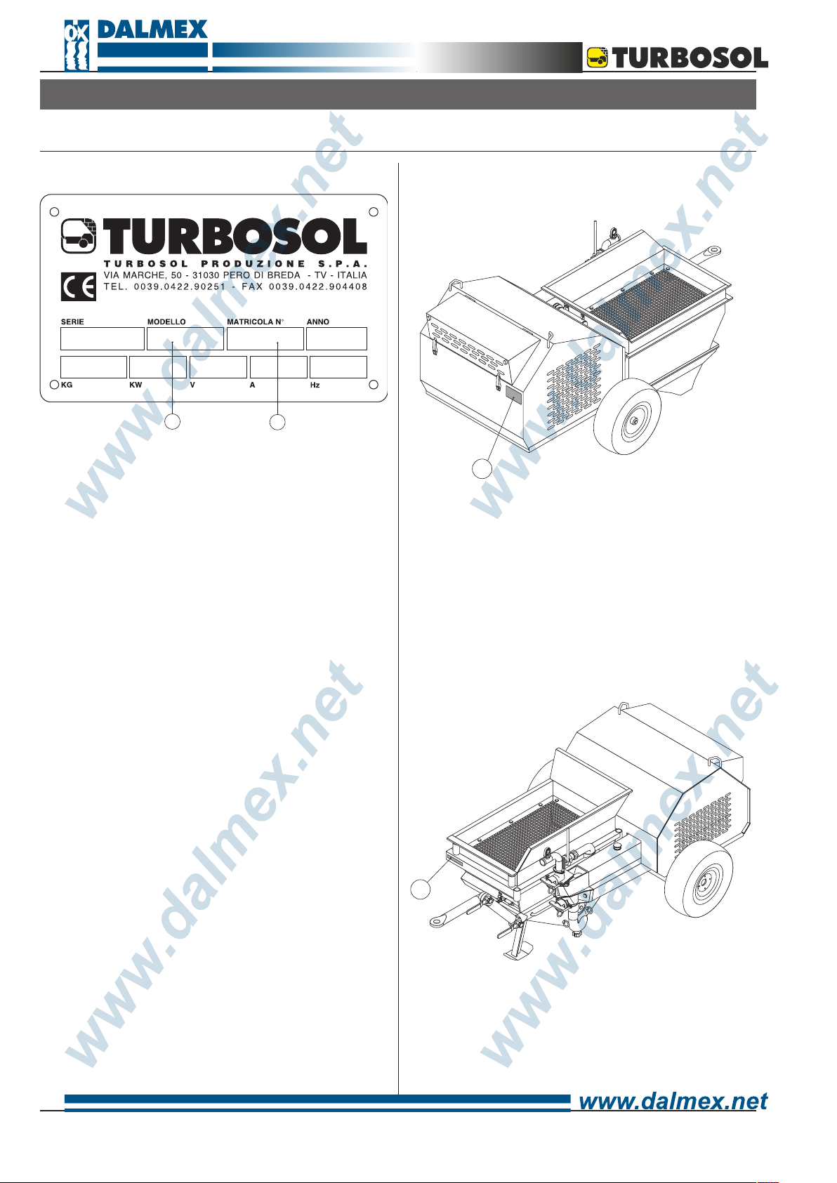
Manufacturer’s registration plate
A
The type of machine (A), its serial number (B), and
data on machine operating power are printed on the
manufacturer’s registration plate.
The meaning of the various symbols used is as follows.
(A) = Type of machine: UNI 30 D (S) (MF)
UNI 30 D = Machine with piston pump
traditional, structural, and special
mortars.
for pumping, conveying and spraying
B
Manufacturer’s registration plate location
1
The manufacturer’s registration plate (1) is attached to
the chassis of the machine.
S = Standard version.
MF = Version with fixed mixer.
(B) = Machine’s serial number: NNNNNN/AA
NNNNNN = The unit serial number.
/AA = Year of manufacture.
Machine’s serial number location
2
The machine’s serial number (2) is printed on the chassis
as well as on the manufacturer’s registration plate.
4.2 - DESCRIPTION OF THE MACHINE
Standard equipment:
• Protection frame for mechanical parts.
• Self-bearing frame with pneumatic wheels and
articulated draw-bar.
• Vibrating sieve with 8 mm mesh.
• Switch board built in accordance to EC norms.
•Piston pump with gravity ball valves.
•Mechanical gearbox with 2 speeds.
•Automatic mechanical safety device against
overpressure.
•Material recycling device
•Built-in air compressor of 270 l/m’ output.
•Positive action mixer of 180 l. (version MF).
•40 m (20+10 Ø 50 +10 Ø 40) of mortar rubber hoses
with cam-lock couplings.
•41 m (31 + 10) of air hose Ø 13 with quick couplings.
• Accessory box with spray gun and a series of nozzles.
• Technical literature.
11
Accessories upon request:
On line pressure gauge for hoses Ø 50.
Pumping nozzle for hoses Ø 40.
Pumping nozzle for hoses Ø 50.
Cement slurry injection device.
Hose extensions:
- Hose extensions of 10 m mortar/air (Ø 50 x 66 e Ø 13 x
19).
- Hose extensions of 20 m mortar/air (Ø 50 x 66 e Ø 13 x
19).
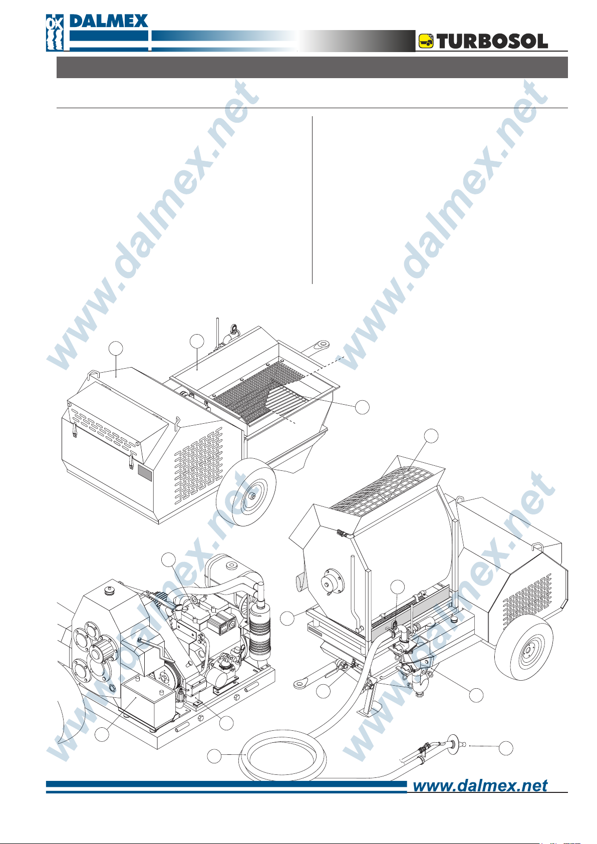
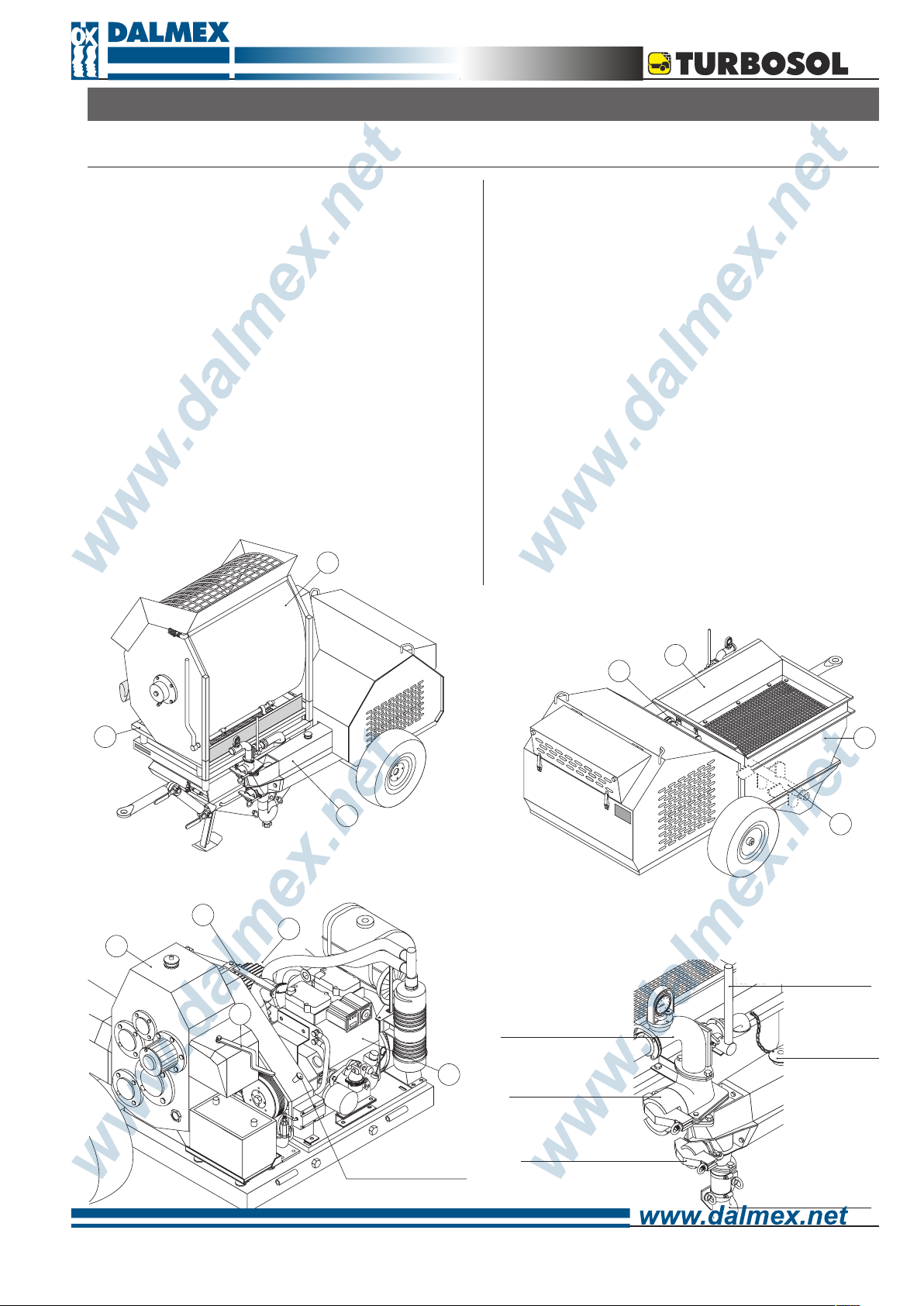
Main components:
The machine is made up primarily of:
a hopper (3) an agitator (4),
a piston pump group (5),
a diesel engine (6) that operates a gearbox (7) with 2
speeds (7a) a safety device (7b) against overpressure,
a compressor (8),
a vibrating sieve (9) operated by a mechanical gearbox (10) and for the MF version: a fixed mixer (11).
9
10
9
5
3
4
7a
8
7
BY-PASS LEVER
7b
DELIVERY OUTLET WITH
PRESSURE GAUGE
6
INSPECTION PLUG FOR THE
DELIVERY VALVE
MUSHROOM SHAPED LID
FOR CYLINDER
ROD ENGINE STOP
INSPECTION PLUG FOR THE
SUCTION VALVE
SUCTION
COLLECTOR
9
10
11
4.3 - SIZE OF THE MACHINE
Here are the size of the machine and its gross weight (ready for use).
Version DS Version DMF
LENGTH WIDTH HEIGHT W EIGHT
2150 mm 1500 mm 110 mm 810 kg
LENGTH WIDTH HEIGHT W EIGHT
2150 mm 1500 mm 1600 mm 1020 kg
4.4 - TECHNICAL DATA
Mortar pump pressure (indicative) 30 bar
Auxiliary circuits voltage 12 V
Engine power 14 kW
R.P.M.
max 2.600 R.P.M.
min 1.200 R.P.M.
Pilot valve fixed pressure max 4,5 bar
Compressor relief valve fixed pressure 6,5 bar
Compressor maximum valve pressure 6,5 bar
Compressor oil change (SHELL RIMULA EXTRA D 15W40) every 100 hours
Gearbox oil change (ELF POLYTELIS 100) every 500 hours
Engine oil change (diesel engine oil 15W40) check engine book
Mixer gearbox oil change (ELF Reductelf SP220) every 500 hours
Hopper capacity 200 l
Mixer capacity 180 l
Delivery distance (indicative) 200* m
Delivery height (indicative) 60* m
1° Part special Ø 50 x 69** mm
Delivery hoses
Extensions normal Ø 50 x 66 mm
Final Ø 40 x 53 mm
Maximum pumpable granulometry 8 mm
Temperature in the work environment from 5° to + 40° C
Sound power level (84/533/EEC) <100 dB(A)
N.B.: * Maximum distance and height cannot be reached at the same time.
** Use only hoses made specially for this machine.
For other data regarding the diesel engine please refer also to the attached engine booklet.
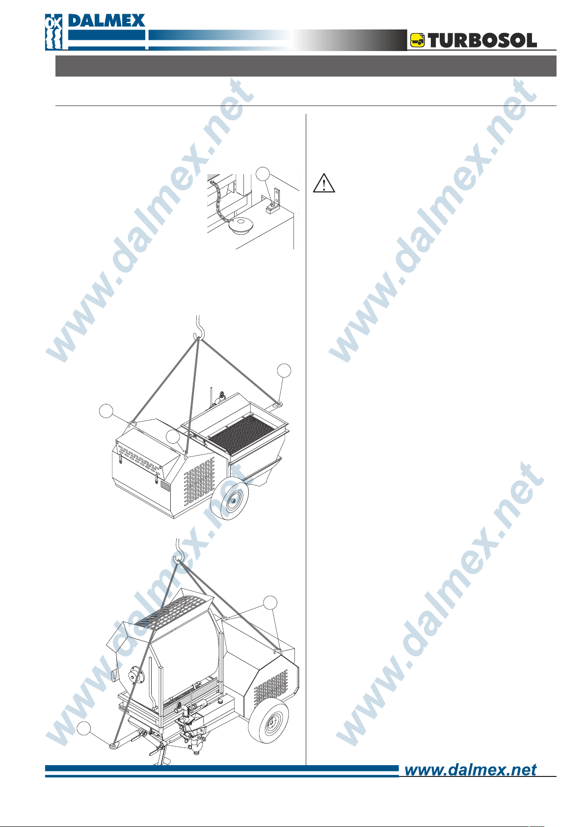
5 - TRANSPORT
5.1 - HOISTING
In order to lift the machine hook the cables up to the
handles (12) of the bonnet (make sure first that the
hooks are closed) and to the tow bar (13).
Use only hoisting equipment, hooks and ropes that have
been tested and approved for lifting at least 1000 kg.
14
• Make sure that the safety screw
(14) that blocks the bonnet is
correctly fixed.
Avoid hoisting the machine with a fork-lift.
Minimum length of the ropes:
- 1,00 m. for the ropes to be connected to the handles.
- 1,30 m. for the ropes to be connected to the tow bar.
13
12
12
Before lifting up the machine, make sure that no one is
standing too close to it.
The mortar mixed separately with whatever kind
of mixer or prepared with the built-in mixer (MF
version), will be discharged on the vibrating sieve of the
machine.
13
12
11
 Loading...