

Turbonics T45, T68, T13 Installation Instructions Manual
Installation:
2
5
32
55mm
7
3
8
188mm
17
432mm
14
17
32
369mm
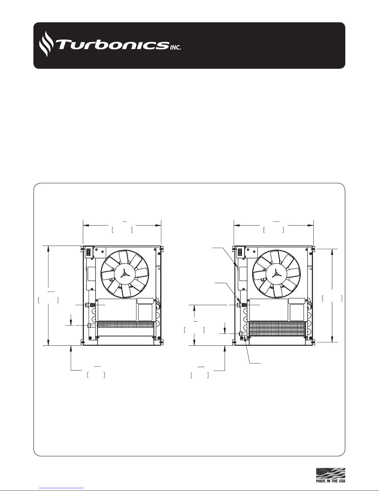
T68-WM
INLET 1/2"
COPPER TUBING
OUTLET 1/2"
COPPER TUBING
WIRING INPUT
18
3
16
462mm
3
21
32
93mm
14
1
4
362mm
T45-WM
CAT-09852-TUR
• Toester Wall-Mount hydronic fan coils are suitable for
connection to a hot water supply at any pressure up to 300
psi with a maximum water temperature of 200°F.
TWMIOM-2
Toester Wall-Mount Fan Coil
Installation Instructions
Model T45/68/13 All Sizes
• Unit is designed to be mounted under or over sheetrock.
Install at least 6" - 8" above the oor for best performance.
Unit will t between standard 16" studs on center.
• Building codes and plumbing regulations may vary.
Check local codes and regulations before determining
proper application and installation.
• Examine unit for shipping damage.
Figure 1 - T45/T68-WM-Top View
• For unit dimensions on the T45/T68 refer to Figure 1, 3, 6
& 7. For T13 refer to Figure 2, 4, 8 & 9.
• Secure unit in proper position. Unit must be level to assure
proper drainage and operation.
1

14
9
16
370mm
21
13
16
554mm
23
584mm
14
9
32
362mm
11
16
18mm
1
1
8
28mm
INLET 1/2"
COPPER TUBING
OUTLET 1/2"
COPPER TUBING
CAT-09853-TUR
T13-WM
Figure 2 - T13-WM-Top View
Piping
• e piping on the unit will usually be copper or any other
locally approved piping. Accessible ½" sweat ttings are
provided on the unit itself. An optional exible stainless
steel connector kit with shut-o valves is available for
connecting the unit to any type of piping system and can
be used with an optional valve control box.
• All piping systems should be designed by a technician
with experience in the various piping arrangements that
work with this type of unit.
• As with any system employing circulated water, the pipes
passing through unheated spaces should be insulated.
NOTE: When using mono-flo or “venturi" fittings, we
suggest placement of a ball valve just after the supply
take-off and before the return is connected.
Piping: Hot Water Boiler
• e unit supply line should be taken from the boiler side
beyond any o-control valve. If the system being used
is a gravity-ow or cast iron hot water system, a separate
circuit must be installed.
Piping: Water Heater
• To install correctly, a technician with knowledge of piping
arrangements and back-o valves must design the piping
system.
Wiring the Unit
• A eld wiring connection is provided on the unit (see
Figure 5). Connect wires at this point only.
• e unit is manufactured with a built-in factory wired
aquastat with a set point of 140°F on and 110°F o. e
aquastat may be disabled in the eld if not required (see
application manuals).
2
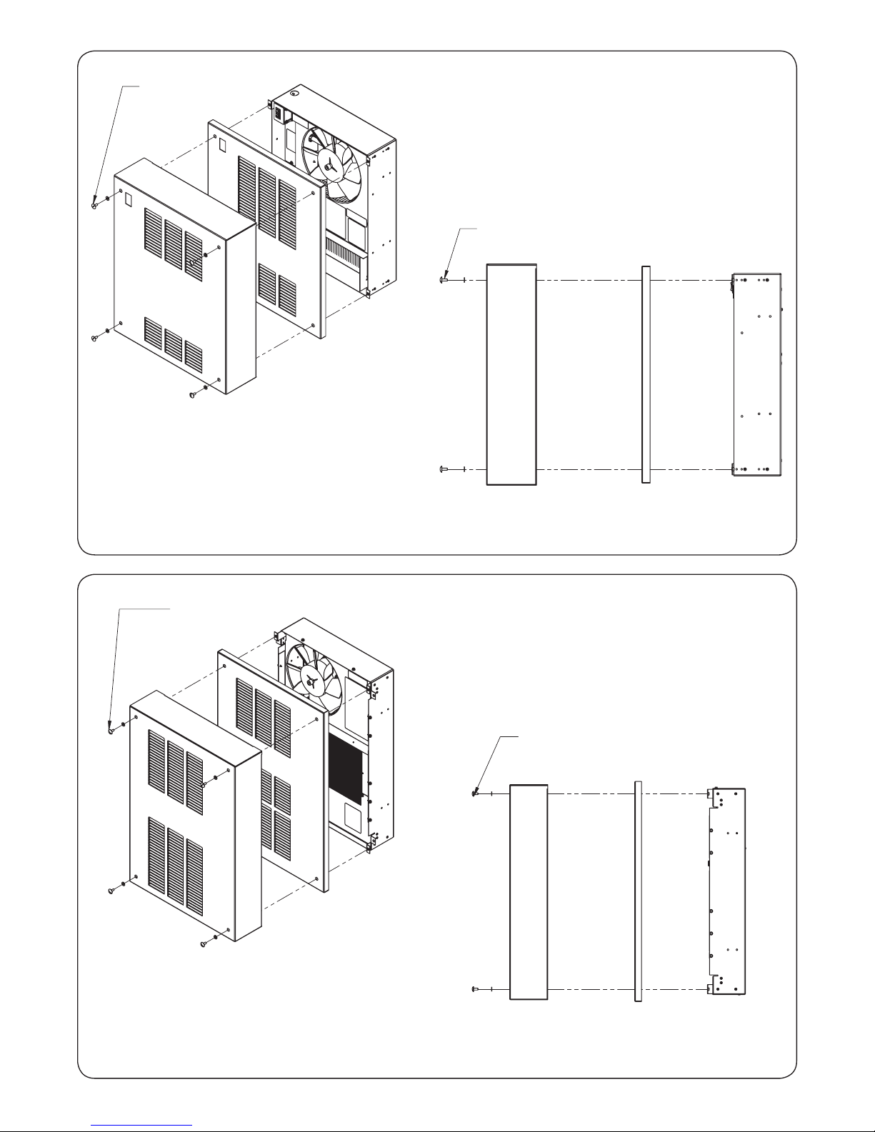
T45/68-WM
RECESSED
COVER
T45/68-WM
SURFACE MOUNT
COVER
T45/68-WM
UNIT
4X #10-32 X 1/2" SCREW
AND NYLON WASHER
(INCLUDED)
CAT-09852-TUR
T45/68-WM
RECESSED
COVER
T45/68-WM
SURFACE MOUNT
COVER
T45/68-WM
UNIT
4X #10-32 X 1/2" SCREW
AND NYLON WASHER
(INCLUDED)
CAT-09852-TUR
4X #10-32 X 1/2" SCREW
AND NYLON WASHER
(INCLUDED)
T13-WM
SURFACE MOUNT
COVER
T13-WM
RECESSED
COVER
T13-WM
UNIT
CAT-09853-TUR
4X #10-32 X 1/2" SCREW
AND NYLON WASHER
(INCLUDED)
T13-WM
SURFACE MOUNT
COVER
T13-WM
RECESSED
COVER
T13-WM
UNIT
CAT-09853-TUR
Figure 3 - T45/68-WM
Figure 4 - T13-WM
3
 Loading...