

Turbonics Kickster KWM Series, Kickster KWM6 VCB, Kickster KWM11 VCB Installation Instructions Manual
Installation:
• Kickster Wall Mount hydronic fan coils with VCB
are suitable for connection to a hot water supply at any
pressure up to 300 psi with a maximum water temperature
of 200°F.
VCBIOM-1
Kickster Wall Mount Fan Coil
Installation Instructions
Model KWM All Sizes with
Valve Control Box (VCB)
• Unit is designed to be mounted under sheetrock for proper
t of the cover. Install at least 6" - 8" above the oor for
best performance. Unit will t between standard 16" studs
on center.
• Building codes and plumbing regulations may vary.
Check local codes and regulations before determining
proper application and installation.
• Examine unit for shipping damage.
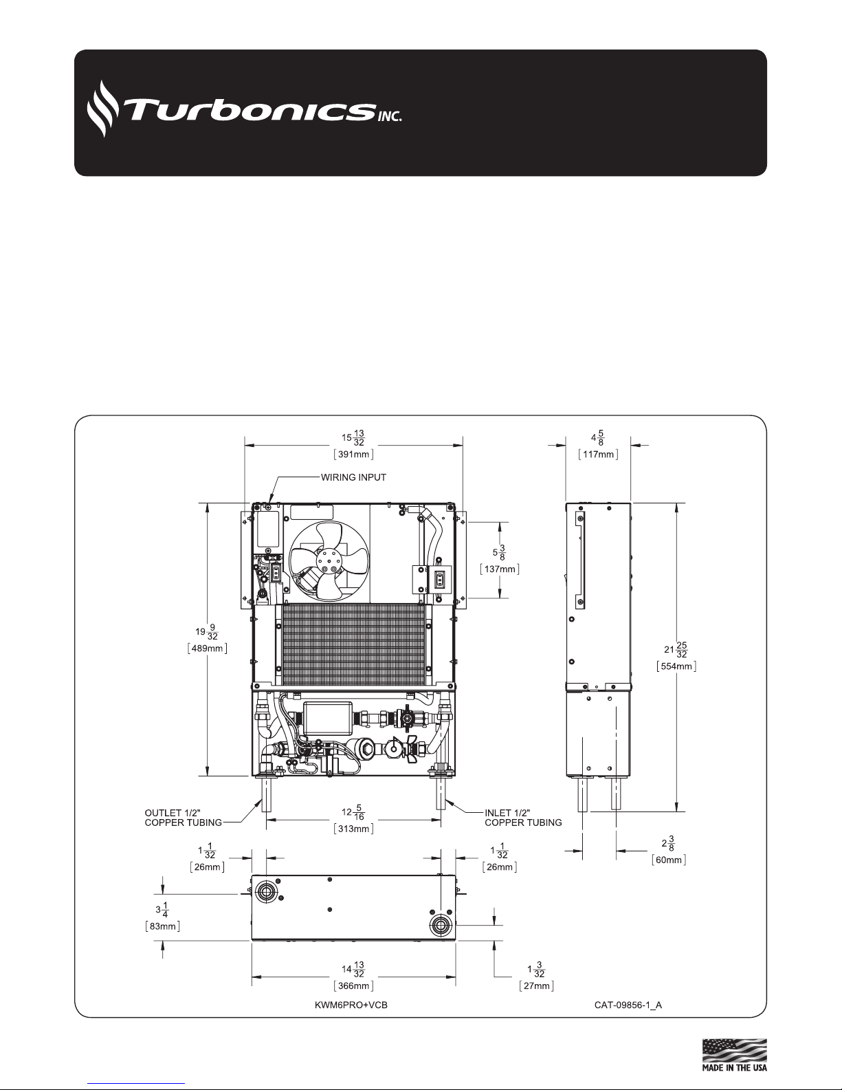
Figure 1 - KWM6 VCB
• For unit dimensions on the KWM6 refer to Figure 1 & 3.
For KWM11 refer to gure 2 & 4.
• Secure unit in proper position. Unit must be level to assure
proper drainage and operation.
1

14
13
32
366mm
1
1
32
26mm
1
1
32
26mm
1
3
32
27mm
3
1
4
83mm
KWM11PRO+VCB
22
9
32
566mm
12
5
16
313mm
15
13
32
391mm
7
1
2
191mm
INLET 1/2"
COPPER TUBING
OUTLET 1/2"
COPPER TUBING
WIRING INPUT
24
25
32
630mm
4
19
32
117mm
2
3
8
60mm
CAT-09856-2_A
Figure 2 - KWM11 VCB
Piping
• e piping on the unit will usually be copper or any other
locally approved piping. Accessible ½” sweat ttings are
provided on the unit itself. For VCB component listing
see Figure 3.
• All piping systems should be designed by a technician
with experience in the various piping arrangements that
work with this type of unit.
• As with any system employing circulated water, the pipes
passing through unheated spaces should be insulated.
NOTE: When using mono-flo or “venturi” fittings, we
suggest placement of a ball valve just after the supply
take-off and before the return is connected.
Piping: Hot Water Boiler
• e unit supply line should be taken from the boiler side
beyond any o-control valve. If the system being used is
a gravity-ow or cast iron hot water system, a separate
circuit must be installed.
Piping: Water Heater
• To install correctly, a technician with knowledge of piping
arrangements and back-o valves must design the piping
system.
Purge and Flush Instructions
After the unit is connected to the water system, verify that
there are no leaks.
1. Close the ball valve on the outlet pipe
2. Open the ball valve on the inlet pipe
3. Remove the brass cap on the purge/flush valve
4. Connect a garden hose to the purge/flush valve and make
sure you are running the hose into a drain or large bucket
5. Open the purge/flush valve. This will purge air from the
system.
6. Continue to flush the system until all air and foreign
matter is removed.
7. Close the purge/flush valve and replace the brass cap
8. Open the ball valve on the outlet pipe.
Prior to Zone valve actuator installation both ball valves
must be open as pressure is applied to the system.
Wiring the Unit
• A eld wiring connection is provided on the unit.
Connect wires at this point only.
• e unit is manufactured with a built-in factory wired
aquastat with a set point of 140°F on and 110°F o. e
aquastat may be disabled in the eld if not required.
• For 24V wiring with transformer see Figure 4.
• For 120V wiring see Figure 5.
 Loading...