

Turbolock tl-200 User Manual

In order to continue serving our customers and providing the best products, our
product information including our user manuals may receive updates from time to
time. Please check our website for the latest user manuals and product materials.
Ver. 1.1 01/05

www.turbolock.com
Customer Service: 855-850-8031
TM

Section 1
Information & Safety Warnings 4
1.1 Introduction 4
1.2 Safety Warnings 4
1.3 Disposal at End-of-Life 5
Section 2
Overview 6
2.1 Package Contents 6
2.2 Product Parts 7
2.3 Battery Information 8
Section 3
Installation (Retrot) 8
3.1 Pre-Installation 8
3.2 Main Installation 10
Section 4
Installation (New) 13
4.1 Pre-Installation 13
4.2 Main Installation 17
Section 5
Using the Lock 19
Section 6
Keypad Passwords 20
6.1 Changing the Admin Password 20
6.2 Adding User Passwords 21
Section 7
Using the Mute Function 22
Muting 22
Un-muting 22
Section 8
The TurboLock App 22
8.1 Installation 23
8.2 Pairing 24
8.3 Generating & Converting Keypad
Passwords 25
How to Generate 25
How to Convert 25
Section 9
Resetting the Lock 26
Option 1 26
Option 2 26
Section 10
Maintenance 27
Section 11
Troubleshooting 27
Section 12
Warranty 29
12.1 Violation 29
12.2 Information 29
Table of Contents

4 TurboLock TL - 200
Section 1
Information & Safety Warnings
1.1 Introduction
This user manual will guide you through the functions and usage of your TurboLock TL-200 Smartbolt. It is important that you
follow all instructions and regard all notes that appear throughout this manual. Consult this manual before you attempt to use
your lock. If you have questions not answered by this manual or are in need of repair or non-routine service, contact customer
service at 855-850-8031. Before contacting customer service, please have your purchase information ready as this may be
needed during the call. This information may be recorded below.
Date of Purchase:
Place of Purchase:
1.2 Safety Warnings
When reading this manual, note these icons:
Notes with this icon MUST be read, understood, and obeyed to prevent injury or damage etc.
Notes with this icon include relevant information.
Overall Usage
• Never insert objects into the lock other than batteries as described in this manual.
• The lock is not a toy. Do not leave children unsupervised around the lock.
• Verify that all parts of the lock are accounted for. If any part is missing, contact customer service.
• The lock is best suited for standard doors made for buildings within the US.
• Use only the parts included in the original packaging or received from TurboLock.

TurboLock TL - 200 5
• Replace the batteries after receiving the lock’s low battery notication.
• Only use clean water, mild cleaner, and soft, non-abrasive cloth when cleaning.
• Never submerge the lock or any of the lock’s components.
• Never apply any cleaner directly to any part of the lock.
• Do not let water and liquids get into the lock’s electric parts or battery compartment.
• Objects should not be hung from the lock’s handles at any time.
• Installation surfaces must be level. Do not install on doors or surfaces with any type of deformity as gaps or warping may
cause the lock to malfunction or fail to operate entirely.
• Old and new batteries as well as batteries from dierent brands may not be mixed.
• Use only four AA batteries.
• Use the lock only as described in this user manual.
• If the battery compartment or surrounding parts are damaged, do not use the lock.
1.3 Disposal at End-of-Life
This product must not be disposed of by incineration, landlling, or mixing with household trash. Improper disposal of the
battery contained within this product may result in the battery heating up, rupturing, or igniting which may cause serious injury.
The substances contained inside the battery present chemical risks to the environment. The recommended disposal for any
TurboLock TL-200 Smartbolt at its end-of-life is to dispose of the entire unit at or through an e-waste recycling center, program,
or facility. Local regulations and laws pertaining to the recycling and disposal of certain batteries and/or products containing
them will vary according to country, state, and local governments. You must check laws and regulations corresponding to
where you live in order to properly dispose of the battery and/or unit. It is the user’s responsibility to dispose of their waste
equipment properly in accordance with local regulations and laws.
For additional information about where you should drop o your batteries and electrical or electronic waste, please contact your
local or regional waste-management oce, your household waste disposal service, or your point-of-sale.
6 TurboLock TL - 200
Section 2
Overview
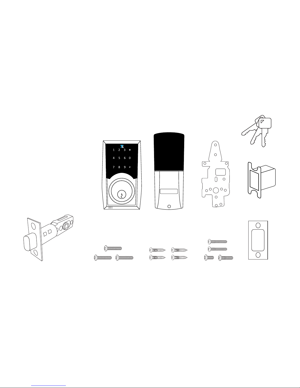
2.1 Package Contents
Outside Section 1x
Inside Section 1x
Plate 1x
Adjustable Latch Assembly 1x
Wood Screws 4x
Inside Screws 4x
Mounting Screws 3x
Keys 3x
Strike Box 1x
Strike Plate 1x
2
3/4
”
2
3/8
”
Outside Section Inside Section Plate
Mounting Screws Inside ScrewsWood Screws
Keys
Adjustable Latch Assembly
2-3/8” (60 mm) or 2-3/4” (70 mm)
Strike Plate
Strike Box
TurboLock TL - 200 7
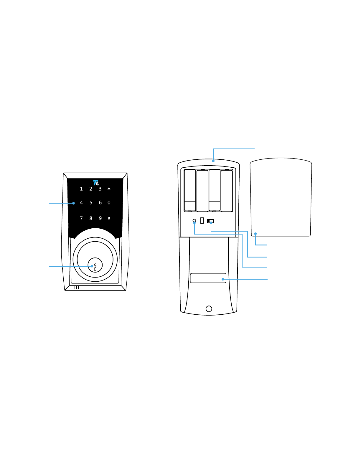
2.2 Product Parts
L R
Keyhole
Keypad
Battery Compartment
(Batteries not included.)
Battery Cover
L/R Switch
Reset Button
Thumb Turn

8 TurboLock TL - 200
2.3 Battery Information
The lock requires four standard or rechargeable ‘AA’ batteries which will be stored inside the back of the lock. New batteries
should be installed as soon as possible after receiving any low battery indication. When the notication begins, the lock will
only have enough power for approximately 50 uses before the batteries are fully depleted. This indication can be received from
the app or the lock itself; the lock will beep after being unlocked. Expected battery life is approximately 365 days.
Section 3
Installation (Retrot)
This section details installation steps needed if you are installing the TL-200 on a door with a single cutout already
made. Replacing an older xture with a newer one is known as a retrot. If your door has never had a lock or
doorknob installed or otherwise has no cutout, please skip to page 13.
• For easier installation, have another person help to hold the lock etc.
• Remove all parts of any old lock before installing the TL-200. In some cases, the old strike plate and/or box may be used.
• For your convenience, installation instructions are broken into segments. Read and follow the instructions for both Pre-
Installation and Main Installation.
• If your door happens to have two cut-outs, check the clearance between the two. Make sure there is enough distance so that
you may seal o any extra opening.
3.1 Pre-Installation
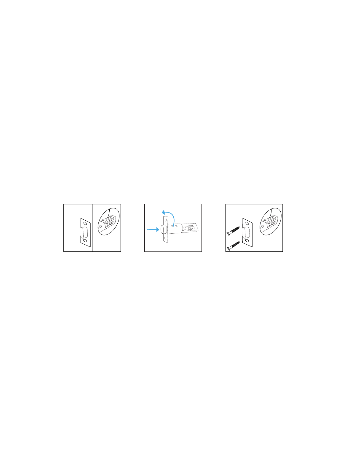
Part 1 Installing the Latch
KEEP DOOR AJAR. At all times during, before, and shortly after installation, keep the door open. If the lock is incomplete or
improperly installed, and the door is then closed, the lock and/or door may become stuck.
TurboLock TL - 200 9
Step 1. Insert the latch into the hole and check it. The latch’s plate should sit ush against the edge of the door. (Fig. 1) If
there’s too much space behind the latch or if it’s sticking out of the door, the latch should be adjusted. If the latch
needs adjusting, move to Step 2. If it doesn’t need adjusting, skip to Step 3.
Step 2. Turn the latch and extend or retract it as needed. Make sure the metal peg pops into one of the two square holes in
the side and the deadbolt is pushed all the way in while adjusting the latch’s length. (Fig. 2) Insert the latch back into
the door.
Step 3. Add 2x wood screws and use a screwdriver (not included) to secure them. (Fig. 3)
Part 2 Installing the Strike
In most cases, the existing strike plate and setup can be used. If you wish to use the one included with your lock, refer to the
instructions for Part 3 on pages 15-16.
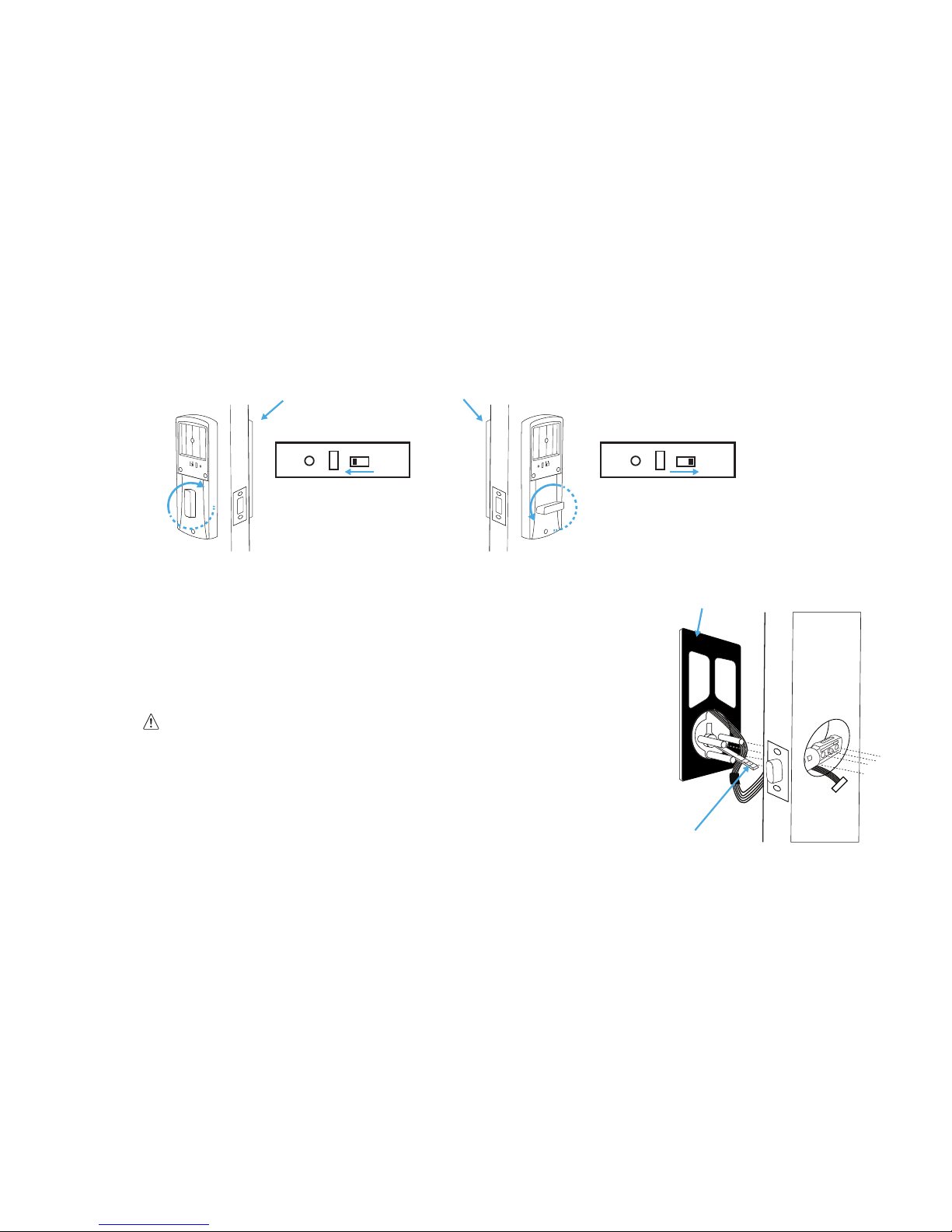
Part 3 Adjusting for Door Orientation
Step 1. With the door open, check it from the back and/or inside of the room. The lock’s parts should be oriented dierently
depending on whether the lock will be on the left side or right side of the door.
2
3
/
4
”
2
3/
8
”
2
3/4
”
2
3/8
”
2
3/4
”
70
60
2
3/8
”
(Fig. 1)
(Fig. 2)
(Fig. 3)
10 TurboLock TL - 200
Step 2. Remove the battery cover from the inside section of the lock and adjust the switch and thumb turn as needed.
3.2 Main Installation
Step 1. Start with the outside section. Feed the power cables under the latch and
thread the latch pin and two of the pegs through the latch; the third and
lowest peg should be under the latch. If needed, have someone hold the
door itself or hold the outside section at against the front of the door. (Fig. 4)
It’s highly recommended to leave the door open and keep the keys in the
lock during installation.
2
3/4
”
2
3/8
”
Left Side Door
Back switch pushed
to L side + thumb turn
vertical
Right Side Door
Back switch pushed
to R side + thumb turn
horizontal
L R
L R
L R
Outside
Section
Outside
Section
(Fig. 4)
Silicone Backing
Latch Pin
 Loading...