

Page 1

Heritage Series ADSL B ridge/ Router
Broadband Sharing
User’s Manual
RT 710
Router
Jly . 2001
Page 2

Heritage Series ADSL B ridge/ Router
Copyright
All rights reserved. No part of this documen t may be reprodu ced in any
form or by any means without written permission from the product
manufacturer.
Chang es are period ically mad e to the informat ion in th is document. They
will be incorporated in subsequent editions. The product manufacturer
may make improvements and/or changes in the product described in this
document at any time.
Page 3

Heritage Series ADSL B ridge/ Router
Contents
Table of Contents
Chapter 1 Product Overview
1.1 Overview 1
1.2 Features and Compatibility
1.3 What’s in the package?
1.4 Important Rules for Safe Operation
1.5 Front Panel
1.6 Real Panel
Chapter 2 Networ k Set- u p
2.1 Preparation for networ k installation 10
2.2 Network installation
Chapt er 3 System Configuratio n
3.1 Get your Broadband Sharing Router Ready 14
3.2 Winsows 95/98 setting for Ethernet LAN connection
3.2.1 C heck TCP/IP p r oto c ol
3.2.2 TCP/IP installation
3.2.3 TCP/IP setting
3.3 MAC OS TCP/IP setting
3.4 Basic Configuration
3.4.1 Sharing a Cable Modem connection (default)
3.4.2 Sharing an always-on ADSL connection
3.4.3 S h aring a dial up A DSL co n nection
3.4.4 Compart you r n e twor k
3.5 Advanced Confi g uration
3.5.1 D e v i ce Informatio n
3.5.2 WAN Port Setting
3.5.3 LAN Port Setting
3.5.4 I P masqurade setti ng
3.5.5 F i re wal l se tting
3.5.6 F i rmwa re upgra d e
3.5.7 PPPoE settin g
1
2
3
4
7
8
9
11
13
15
15
17
19
21
22
22
25
27
29
30
30
31
32
34
35
36
37
Page 4

Contents
Appendix
Appendix A Glossary
Appendix B Product Specifications
Appendix C Troubleshooting
A1
A8
A10
Appendix D Government Compliance Notices A13
Page 5

Heritage Series ADSL B ridge/ Router
Introduction
1
Chapter 1 Int roductio n
1.1
The RT710 Broadband Sharing Router is an easy installation Router to
share a single xDSL or Cable Modem broadband connection with your
family members or colleagues. With the minimu m hardw are investment,
you can easily sharing your broadband connection direct to 4 computers
with build-in 10/100Base-T stackable switching HUB. More local
connections (253) can be expanded with dumb or switching HUB
distribution.
The RT710 Broadband Sharing Router is also a LAN-to-LAN Router and
can easily divide your local networks into a separated and secured section.
With IP filtering and password protection, you can remain your network in
private and safe.
Product Over vi ew
Page 6

2
Introduction
1.2 Features and Compatibility
The RT710 Broadband Sharing Router provides the following features:
Protocol
•
DHCP: RFC1541 (Client and Server Function)
•
IP: RFC791
•
ARP: RFC826
•
UDP: RFC768
•
TCP: RF C7 93
•
RIP: RFC 1058
•
PPP: PP PoE support for ADSL
•
NAT/IP Masqurade
Networking Management
•
Web based configuration through Ethernet interfaces
•
Syslog for recordin g conn ection log
•
Teln et and TFTP for firmw are update and configuration file
backup and restore
Firewall
•
Packet Filtering and Port Filtering for controlled access t o
and from your network
Page 7

Heritage Series ADSL B ridge/ Router
Introduction
3
1.3 What’s in the package?
!"
One RT710 Broadband Sharing Router
!"
One 9V AC Adap to r
!"
One 10Base-T Ethernet straight-through Cable
!"
On e Us er Gu i d e
All packages have been checked carefully for their completeness and
functionality before shipped. Please contact the place of purchase if any of
the above listed items is missing or damaged.
If you encountered any difficulty in using this produ c t while all th e above
items are complete, please refer to
informat ion before making t he decision to re turn your Broadband Sharing
Router to your dealer.
Appendix C
for Troubleshooting
Page 8

4
Introduction
1.4 Important Rules for Safe Operation
In addition to the careful attention devoted to quality standards on the
manufacture of your Router, safety is a major factor in the design of every
product . However, safe ty is your resp onsibility, t oo. This section lists
important information that will help assure your enjoyment and proper use
of the Router and accessory equipment. Please read them carefully before
operation an d u s in g you r Modem.
!"Read and Follow Instructions
operatin g ins tr u ction s be fore operat in g t he Rou t er.
Retain Instructio ns
!"
instruction s, for your future reference.
Heed Warni ng
!"
the opera ting inst ru ct ions .
Check Power Sources
!"
power source indicated on the product’s marking label. If you
are not sure of the type of power supplied to your home, consult
your d eale r or local power company.
Be Carefu l of Overload ing
!"
exten sion cord s, a s this can re su lt in a risk of fire or el ectr ic sh ock .
Overloaded AC outlets, extension cords, frayed power cords,
damaged or cracked wire insulation, and broken plugs are
dangerous. They may result in a shock or fire hazard.
Periodically examine the cord, and if its a ppearance indicates
damag e or deteriorated insul ation, have it replaced by your
servi ce tech n icia n.
Protect Power Cords
!"
not likely to be walked on or pinched by items placed upon or
against them. Pay pa rticular attention to cords where they are
attached to plugs and convenience receptacles, and examine the
point where they exit from the product.
Check Ventilation
!"
provid ed for ventilat ion to ensure rel iable operation of the
product and to protect it from overheating. Do not block or cover
these openings. Never block these openings by placing the
product on a bed , sofa , ru g , or othe r simil ar su rfa ce . Nev e r plac e
this product near or over a radiator or heat register, or an y oth er
heat source (including amplifiers). Do not place this product in a
– You should save all the safety and operating
– Comp ly with all wa rning s on th e prod ucts and in
– Operate this product only from the type of
– Route power supply cords so that they are
– Slots and openings in the enclosure are
– you should read all the safety and
– Do not ove rload wall outlets or
Page 9

Heritage Series ADSL B ridge/ Router
Introduction
built-in installation, such as a bookcase or equipment rack, unless
you prov id e proper ve ntilation .
Do Not Use Accessories
!"
– Do not use attachments, unless they are
recommended by your vendor, as they may cause electrical or
fire ha zard s .
Use the Recommended Power Adaptor
!"
– You must use the Power
Adaptor that comes with your product.
Do Not Use Near Water
!"
– Do not use this product near water. For
example, near a swimming pool, bathtub, washbowl, and the
like.
Do Not place Near High Temperature Source
!"
a steamer, kitchen range fire, and the like.
Use Caution in Mounting This Product
!"
– Do not place this
product on an unstable surface or support. The product may fall,
causing serious injury to a child or adult, as well as serious
damage to the product.
!"Use Care in Moving Product-and-Cart Combinations
stops, excessive, force and uneven surfaces may cause the
product-and-cart combination to overturn.
Unplug Power Before Clea ning
!"
– Do not use liquid cleaner or
aerosol clea ner. Us e a damp cloth for cleaning.
Keep Objects Out of Op enings
!"
– Never push objects of any kind
into this product through openings, as they may touch
dangerous voltage or “short-out” parts, which could res ult in a
fire or electric sh ock. Neve r spill liquid on the product.
!"Protect From Lightning
– For added protection for this product
during a lightning storm, or when it is left un attended and
unused for long periods of time, unplug it from the wall outlet,
and disconnect the cable system. This will prevent damage to the
product due to lightning and power line surges.
Turn Off the Power Switch Between DC Plug Off and On.
!"
Do Not Remove Cover s
!"
– Do not attempt to service this product
your self, as opening or r emovin g cove rs may expose you to
dangerous voltage or other hazards.
Unplug this Product F rom Wall Outlet Carefully, as the Power
!"
Adaptor May Be Hot.
5
– Fo r example near
– Quick
Page 10

6
Introduction
Refer Servicing to Qualified Service Personn el Under the
!"
Conditions Listed Below.
#"
When the power supply cord or plug is damaged.
#"
If liqu i d ha s b ee n s pil led or obje cts ha ve fal le n in to t he
product.
#"
If the product has been exposed to rain or water.
#"
If the product does not operate normally by following the
operating instruction s. Ad j ust only th ose controls that are
covered by the operating instructions.
#"
If the product has been dropped or the cabinet has been
damaged.
#"
When the product exhibits a distinct change in
performance , s u ch a s th e ina b il it y to perform ba s ic
functions – this indicates a need for service.
Require Safety Check
!"
to this product, ask the service technician to perform safety
checks recommended by service point to determine that the
products is i n safe operating condit ion.
– Upon completion of any serv ice or repairs
Page 11
7
Heritage Series ADSL B ridge/ Router
Introduction
1.5 Front Panel
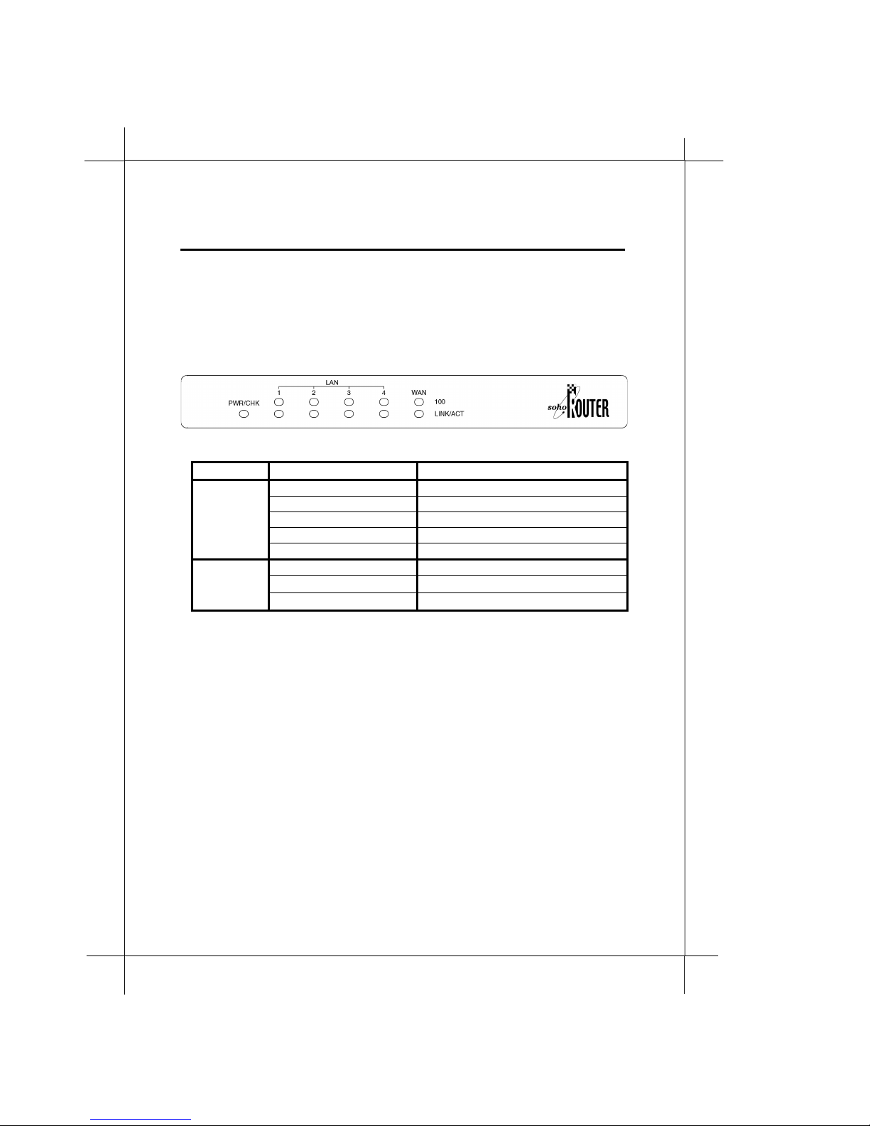
The RT710 Broadband Sharing Router has 11 status LEDs for diagnostics.
You can monitor the LEDs during operation. Following table shows the
Router status LEDs and identifies what each LED light means.
Function Behavior Definition
PWR/CHK
L1~L4,
WAN
* Upper row of L1~L4 and WAN LEDs represent 100Base-T connections and lower row of
L1~L4 and WAN LEDs represent 10Base-T connections.
Dark Power off
Flash (Green) System boot-up
Light (Green) System Ready
Flashing slowly (Red) Firmware uploading
Flashing quickly (Red) Firmware writing
Dark Ethernet link absent or power off
Light Ethernet link present
Flashing Data transmission
Page 12

8
Introduction
1.6 Rear Panel
The rear panel of the RT710 Broadband Sharing Router consists of power
jack, WAN P ort conn ect or, 4 L AN port conn e ctors a nd fa ctory
switch as shown below:
The WAN port is presented as a MDIX RJ45 connector. You can connect it
to your cable modem/ADSL with a straight-through Ethernet cable, or to
anoth er HUB wit h a crossov er Et h e rne t cab le.
L1~L4 LAN port s are auto-MDIX ports which are not limited to a single
uplink port as other dumb HUB. You can use a straight-through or
crossover cable to connect any device creating a greater increase in
flexibility.
DEFAULT
Page 13

Heritage Series ADSL Bridge / Router
Network Set-Up
9
Chapter 2 Network Set-Up
The RT710 Broadband Sharing Router is a featured network device and
will be one of the network members. Please make sure you configure your
Router properly before you put it on network. Inadequate netw ork
configuration may cause problms to other network device or even paralyze
the whole network.
Page 14
0
1
Network Set-Up
2.1 Preparation for netw ork installation
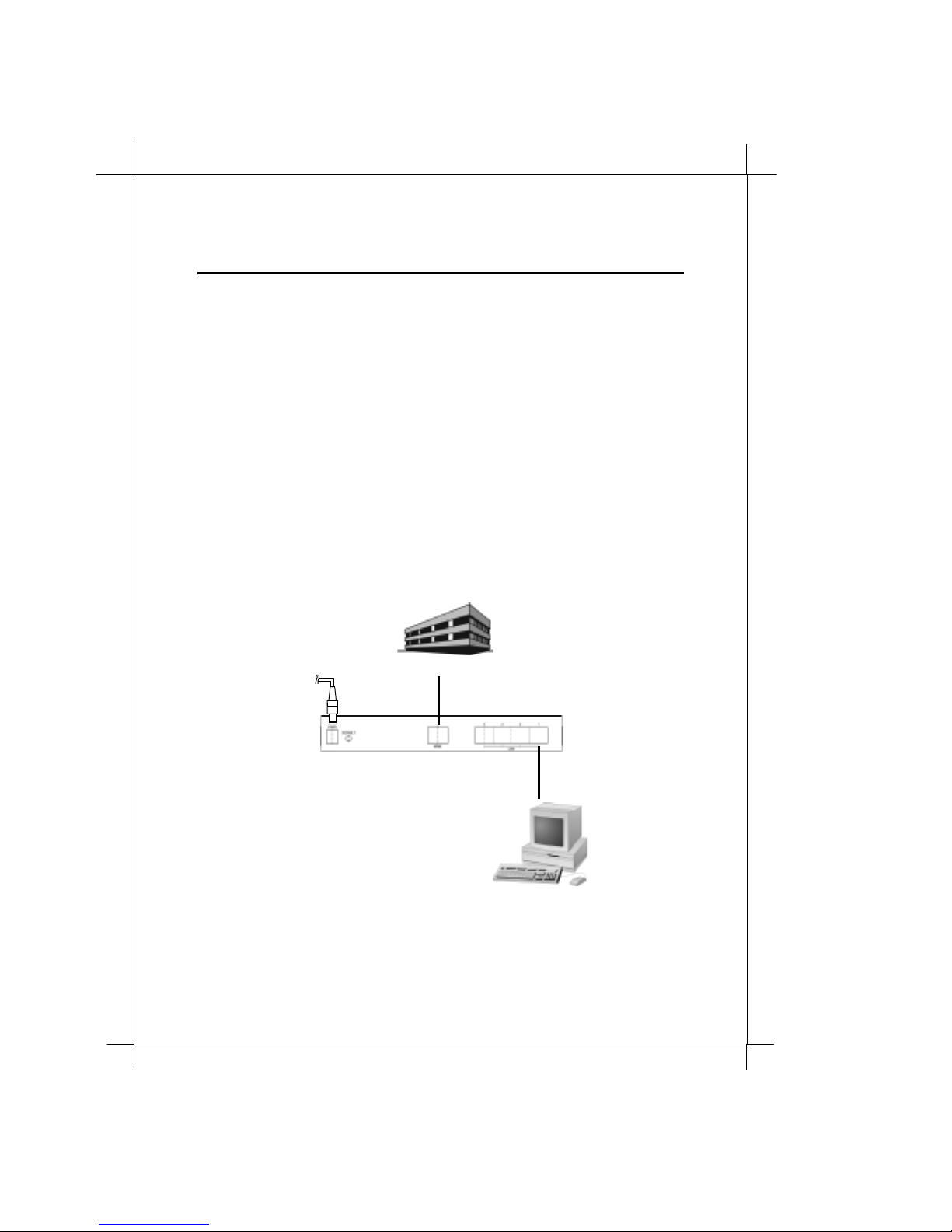
Before start the network installation. Please prepare all the materials listed
below regarding to your application.
1. Connect to a computer directly
!"
Network service provider s ervice cont ract or permit from
corporate n etwork adminis trator. Please sign an
appropriat e Int ern et con ne cti on contra ct wi t h a re lia bl e
ISP/NSP and get necessary connection information.
!"
Personal computer with OS that support Ethernet interface
!"
TCP /IP prot ocol installed in your pers onal computer
!"
10 or 100Base-T Ethernet card
!"
10or 100Base-T Ethernet cable (a straight-through cable is
included in this package)
!"
Power adapt or ( i nclud e in this package)
AC Adaptor
MSO/NSP
WAN Port
Basic connection to configure your Broadband Sharing Router
LAN Ports
Page 15
Heritage Series ADSL Bridge / Router
Network Set-Up
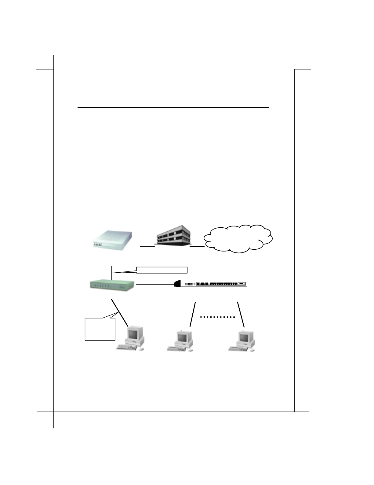
2.2 Network installation
1. Connect the power adaptor to the power jack that marked
at the rear panel of the Router, then plug in the AC power
adaptor to the wall electrical outlet.
2. Connect the LAN cable.
Connect one end of 10Base-T Ethernet cable (straight through
or crossover) to the LAN ports on the rear panel, and then
conn ec t t he oth er en d of 1 0Base- T Et herne t cable t o PC s , HUB
or other net work de vi ce.
3. Connect the WAN cable.
Connect one end of 10Base-T Ethernet straight through cable
to the WAN port on the rear panel, and then connect the other
end of 10Base-T Ethernet cable to Cable Modem, ADSL or
corporate n etwork.
Cable Modem/ADSL/
Corporate Network
Straight Ethernet Cable
MSO/NSP
Internet
11
Power
Broadband Sharing Router
Straight or
crossover
Ethernet
Cable
Dumb HUB or switc h HUB (s)
Network configurating dia gram
Page 16

2
1
Network Set-Up
Page 17

Heritage Series ADSL B ridge/ Router
Syste m Configuration
13
Chap ter 3 System Con figuration
The RT710 Broadband Sharing Router built-in a web based system
configuration server. You can easily access the server with any popular
browser (i.e. Microsoft Internet Explorer or Netscape Navigator) through
LAN port of the Router. How ever, you should make sure your TCP/IP and
browser are ready to access the Router before configuration.
If your network and PC are properly setted up and need no further help on
these subjects, you can directly go
Advancedd Configuration
.
3.4 Basic Configuration
or
3.5
Page 18
4
1
Syste m Configuration
3.1 Get your Broadband Sharing Router rea dy
Before start your system configuration, it is better to reset all system
configuration s to factory default.
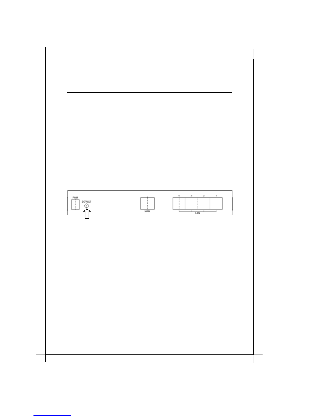
To reset the system configuration
1. Power off the Router
2. Press the DEFAULT button on the back of Router steadly.
3. Plug in the power plug wh ile DEF AULT button is pressed.
4. Let go the DEFAULT button after the Router entering system
boot-up process ( PWR/CHK LED fl ash quickly on green.)
5. Wait for the boot-up un til system read y (PWR/CHK LED lit
steadly on green.) and go for further operations.
Press the DEFAULT
button steadly
Page 19
Heritage Series ADSL B ridge/ Router
Syste m Configuration
15
3.2 Windows 95 / 98 setting for Ethernet LAN
connection
The RT710 Broadband Sharing Router is working on TCP/IP protocol. You
have to make sure your LAN card is properly installed and TCP/IP
protocol is binded with this accessing LAN card .
Since the Broadband Sharing Router build-in a
recommand ed to confi g u re you r compu te r to obt ain an
automatically from Router’s
your LAN card, please make sure your
the same subnet as the Router. The default su bnet is from 192.168.100.2 to
192.168.100.254. Following steps provides the instructions to setup your
computer to obtain an IP address by using Windows 95/98 on a PC.
DHCP server.
IP address
DHCP server
If you want to assign an IP for
and
, you are
IP address
Subnet Mask
is in
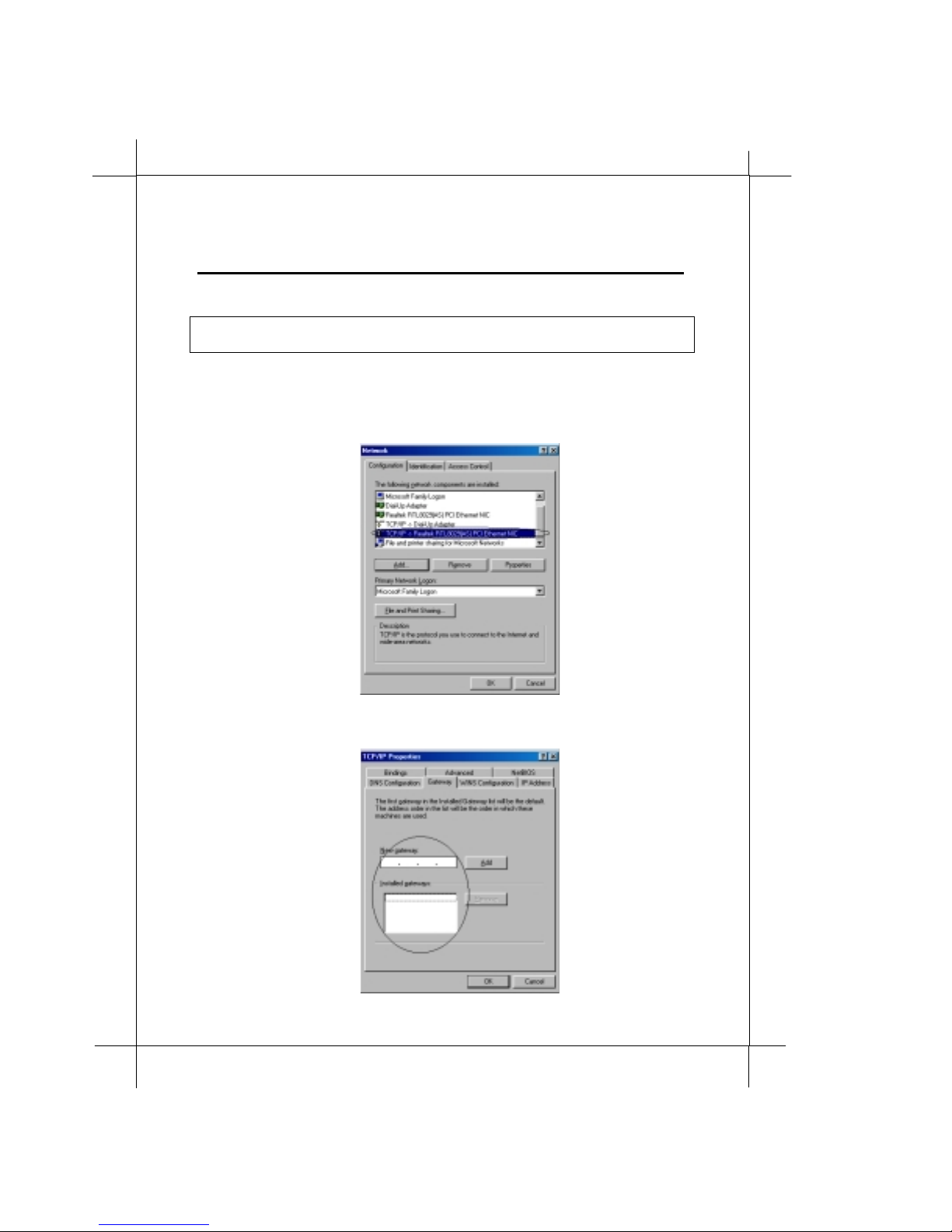
3.2.1 Check TCP/IP protocol
To check if T CP/IP is properly installe d, please proceed to the following
steps.
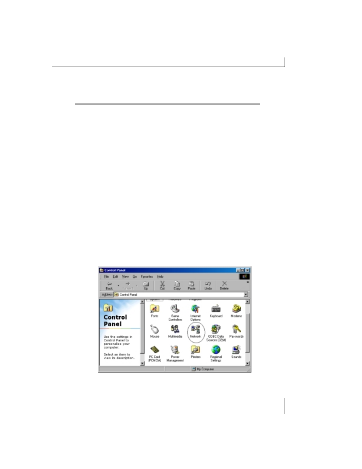
1. Double-click on
My comp uter->Control P anel->Network
Page 20
6
1
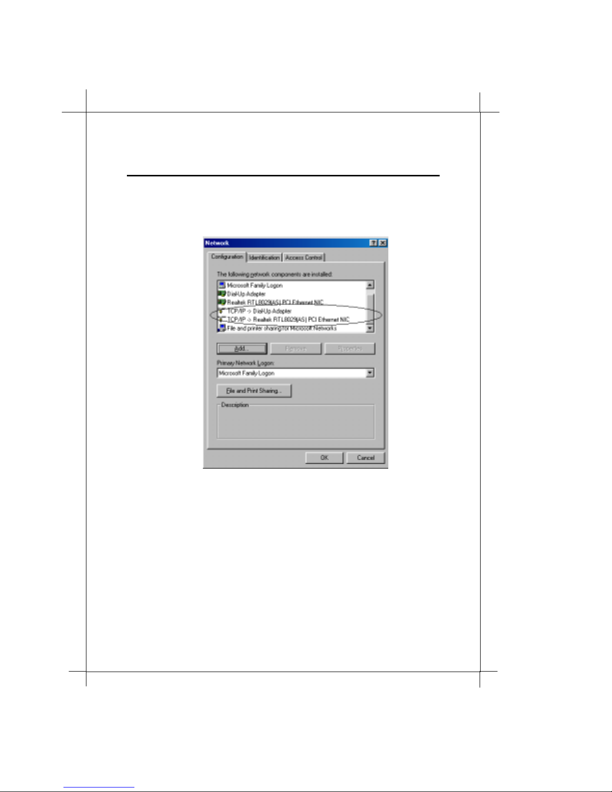
2. In
Syste m Configuration
Network
setup for the Ethernet card that in stalled in your computer (for
example,
window, check if
TCP/IP->Realtek RTL8029(AS) PCI Ethernet NIC
TCP/IP
is shown and properly
).
3. When TCP/IP has properly installed, please proceed to 3.2.3
TCP/IP Setting
4. When TC P/IP has not properly installed, go to next section to
inst all t he TC P/IP protocol.
Page 21
7
Heritage Series ADSL B ridge/ Router
Syste m Configuration
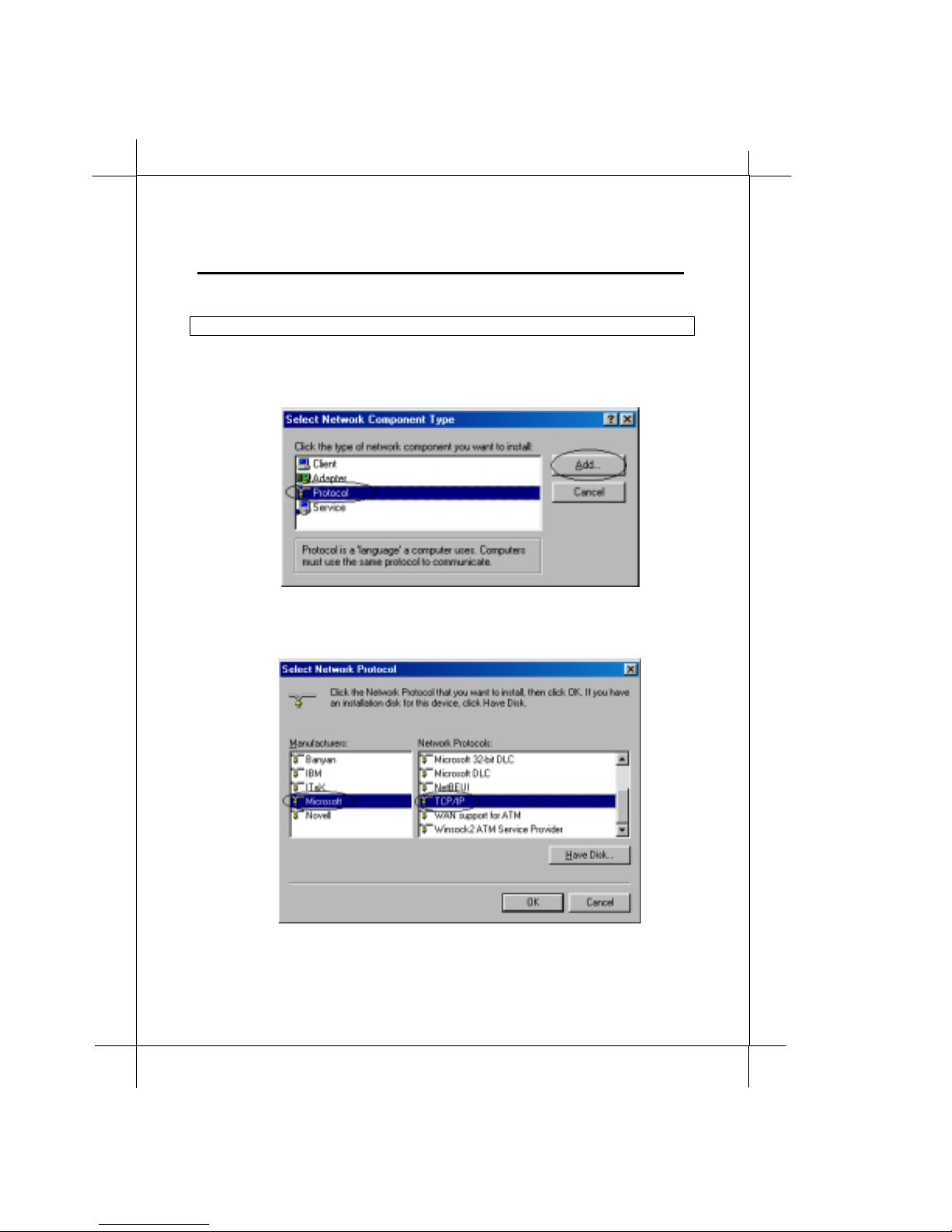
3.2.2 TCP /IP installatio n
Attention: When install TCP/IP protocol, you need Windows CD-ROM
1. In
2. Choose the
3. In
Manufacturers
Network
Select Network Protocol
window, click the
Protocol
and
and click
TCP/IP
Add
button.
Add
.
window, choose
Network Protocols
in
Microsoft
in
. Then click OK
1
Page 22
18
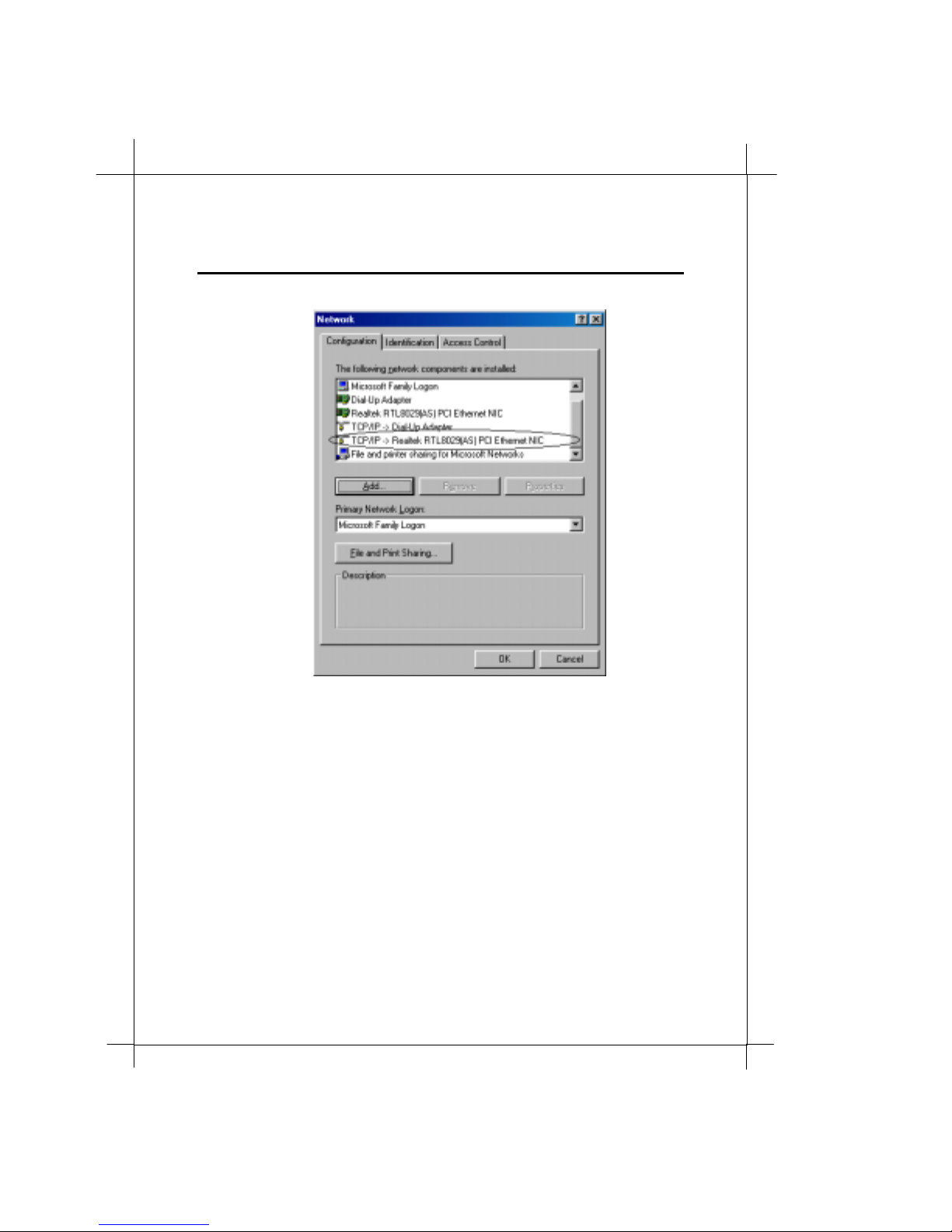
4. Confirm if the TCP /IP protocol has been correctly setup with
your Ethernet card.
Syste m Configuration
Page 23
Heritage Series ADSL B ridge/ Router
Syste m Configuration
19
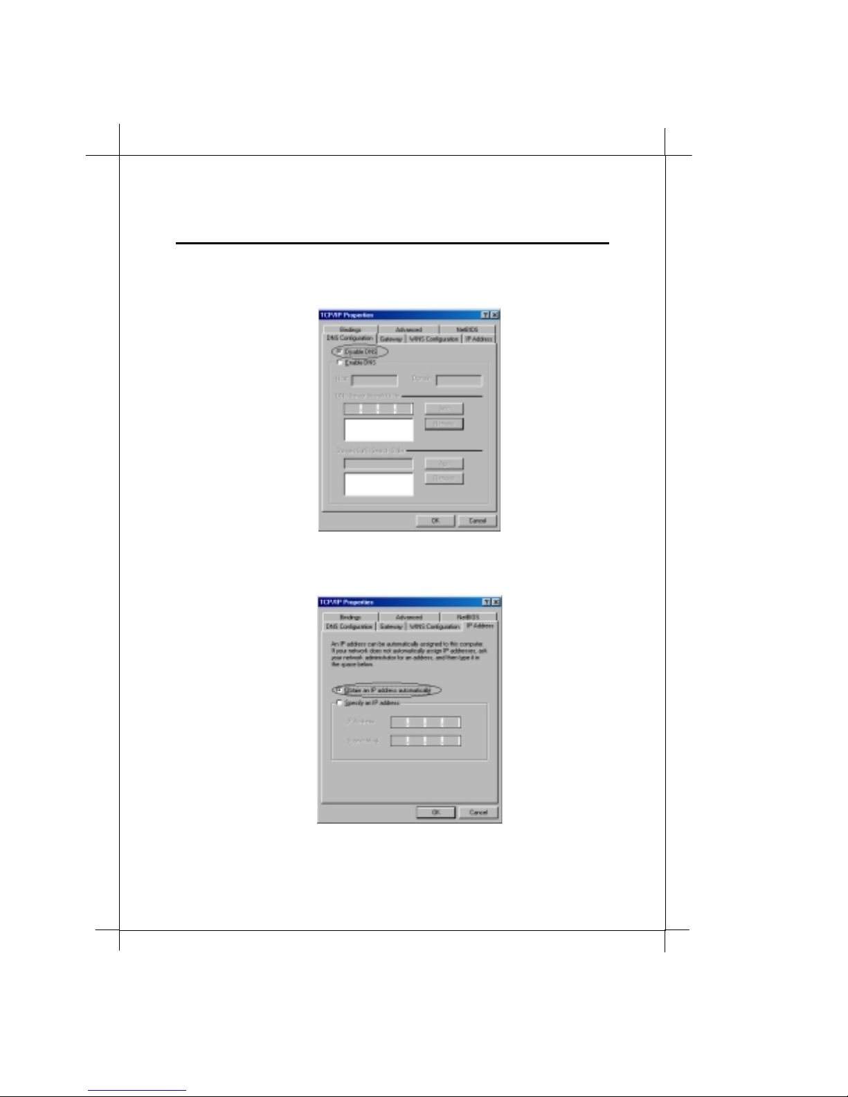
3.2.3 TCP/IP setting
Attention: When connecting your Router with existing LAN, consult your
network manager for correct configurations
Network
1. In
Eth ernet card that installed in your computer(for example,
TCP/IP > Realtek RTL8029(AS) PCI Ethernet NIC
2. Click the
window, double-click th e TCP/IP service for the
).
Gateway
tab, and remove any installed gateways.
Page 24
0
2
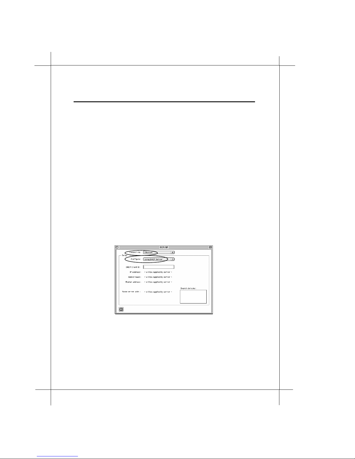
3. Click the
button.
4. Click the
automatically
Syste m Configuration
DNS configuration
IP address
tab, and click the
button.
tab, and click the
Obtain an IP address
disable DNS
To assign an IP directly, Click the
Specify an IP address
IP address
button. Then set
tab, and click the
IP Addre ss
and
Subnet
Page 25
Heritage Series ADSL B ridge/ Router
Mask
to the same subnet. (Default: 192.168.100.2
~192.168.100.254)
5. Click OK to save the new setting.
6. Click
7. Now your computer is ready to access your Modem via Ethernet
Yes
when prompted for “
computer ?
in effects.
network.
”. Your computer will restart to make the new setting
Syste m Configuration
Do you want to restart your
21
3.3 MAC OS TCP/IP setting
Please follow the below mentioned procedure for TCP/IP Protocol Setup.
1. Choose
2. Set y our displ ayed window by choosing
and
(Remember to save the setup.)
Apple Menus
Using DHCP Se rve r
Control Panels
->
Configure
at
TCP/IP
->
Ethernet
and close the window.
.
Conn ect via
at
Page 26

2
2
Syste m Configuration
3.4 Basic Configuration
There are four basic network connection types with this Router: 1) share a
cable modem, 2) share a leased line ADSL, 3) share a dial-up ADSL and 4)
compart your private network.
This section specifies how to configure all these four basic networks. For
Adv an c ed d net work co nf i gur at i o n, p l ea s e go
3.4.1 Sharing a Cable Modem connection (default)
Cable Modem connection is widely accepted by home users. Most
broadband service providers (
without static IP assignings. In stead, they assign IP dynamically every
time the subscriber log on to the system.
You should configure the RT710 Broadband Sharing Router WAN port to
accept dynamic IP ass igments . Factory defau lt configuration was set for
this type of network connection and need no further settings. However, in
any circumstance you want to configure the Router to share a Cable
Modem con nection.
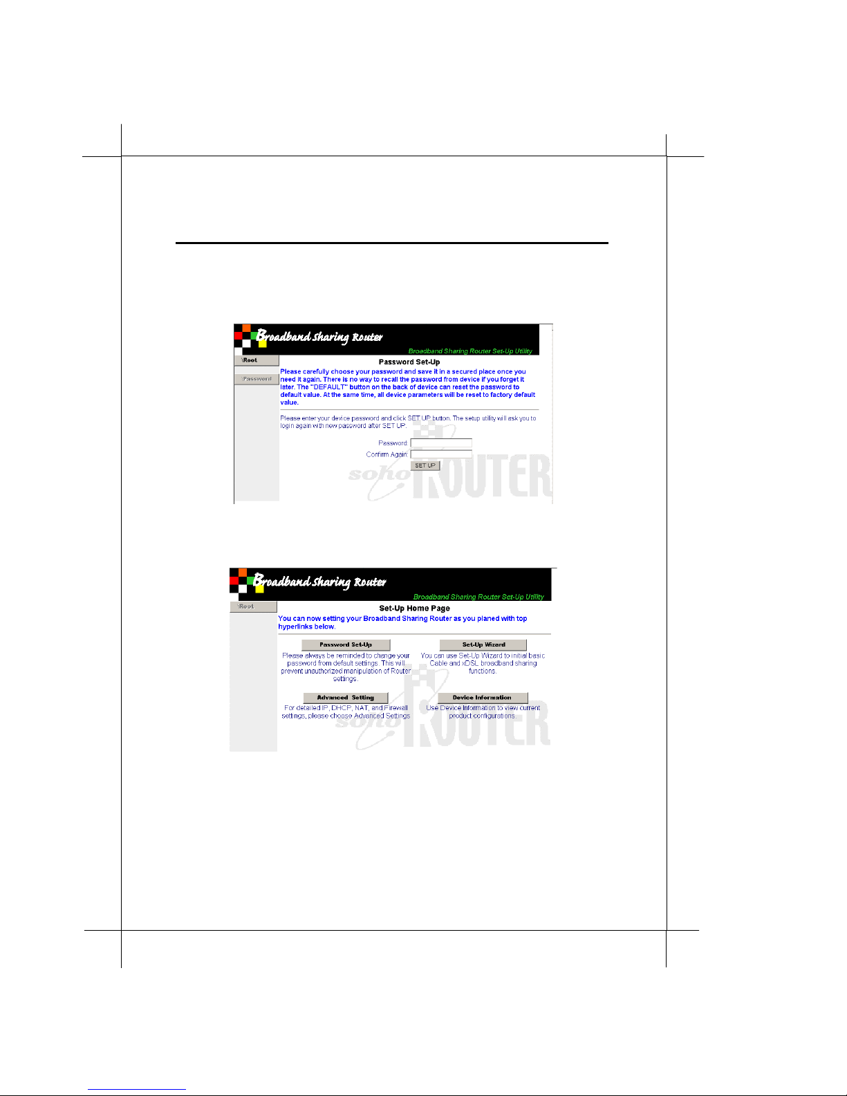
1. Running your browser and go URL:
access the system configuration server. (If you changed the LAN
port IP, please use the new IP.)
NSP
or
MSO
3.5 Advanced Configuration
) offer an always-on connection
“http://192.168.100.1”
to
.
Page 27
Heritage Series ADSL B ridge/ Router
Syste m Configuration
2. Enter system configuration password. (The default password is
“admin” case sensitive. For security reason , please do change the
password from factory default immediately to prevent
unauthorized change of Router settings.)
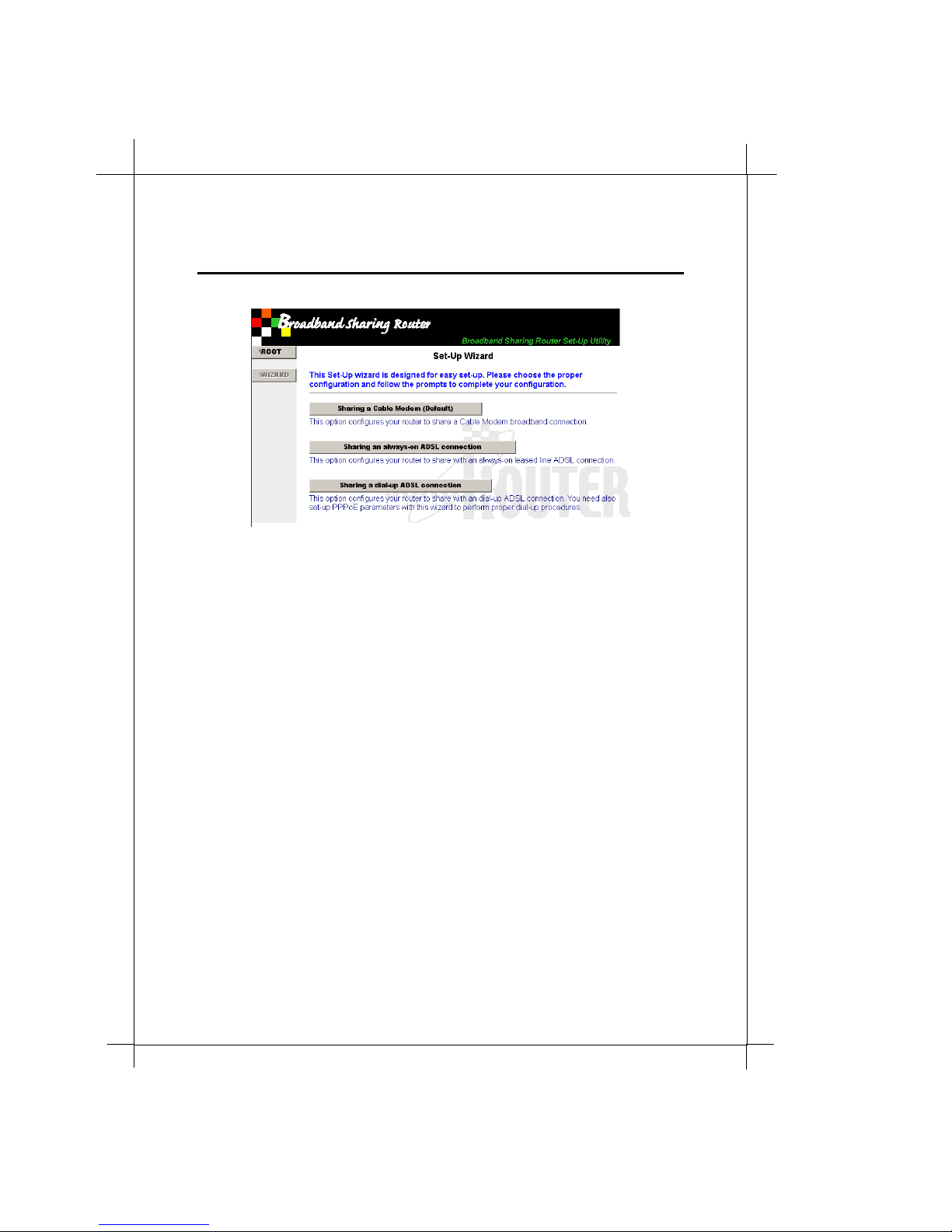
3. Click on
Set-Up Wizard
23
Page 28
4
2
4. Click on
Sharing a Cable Modem
Syste m Configuration
5. Double confirm the conf iguration. C lick
configuration , NO to cancel this setup.
YES
to accept this
Page 29
Heritage Series ADSL B ridge/ Router
3.4.2 Sharing an always-on ADSL connection
Syste m Configuration
25
Always-on ADSL connection, also called leased line ADSL connection, is
widely accepted by SOHO (Small Office and Home Office) and e nterprise
users. If you apply a leased line ADSL connection, like other subscribe lines ,
a fixed or “real world” IP is ususlly included in the package. Sometimes
your network service provider (
with this ADSL line.
To adopt with this ADSL always-on network, the Broadband Sharing
Rout er shoul d configure its WAN port to the fixed IP provided by NSP.
1. Running your browser and go URL:
access the system configuration server. (If you changed th e LAN
port IP, please use the new IP.)
2. Enter system configuration password. (The default password is
“admin” case sensitive. For security reason , please do change the
password from factory default immediately to prevent
unauthorized change of Router settings.)
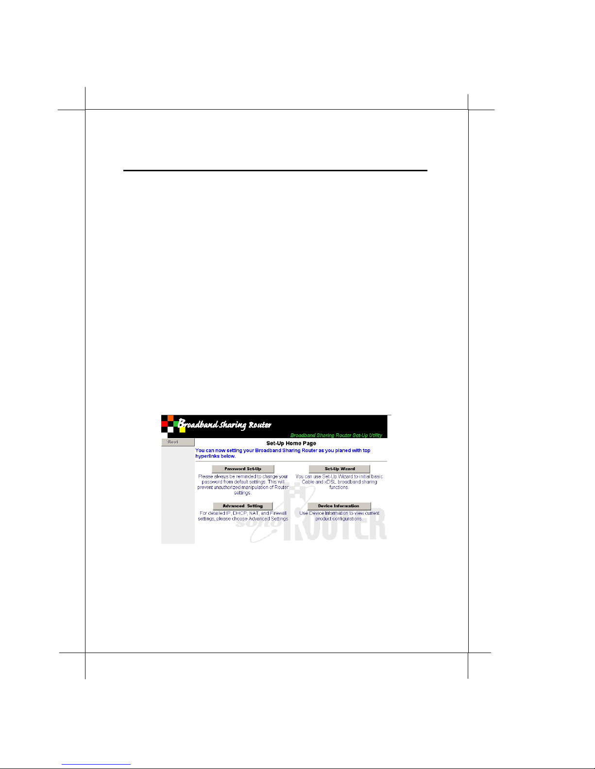
3. Click on
Set-Up Wizard
NSP
) will offer more than one IP address
“http://192.168.100.1”
to
Page 30
6
2
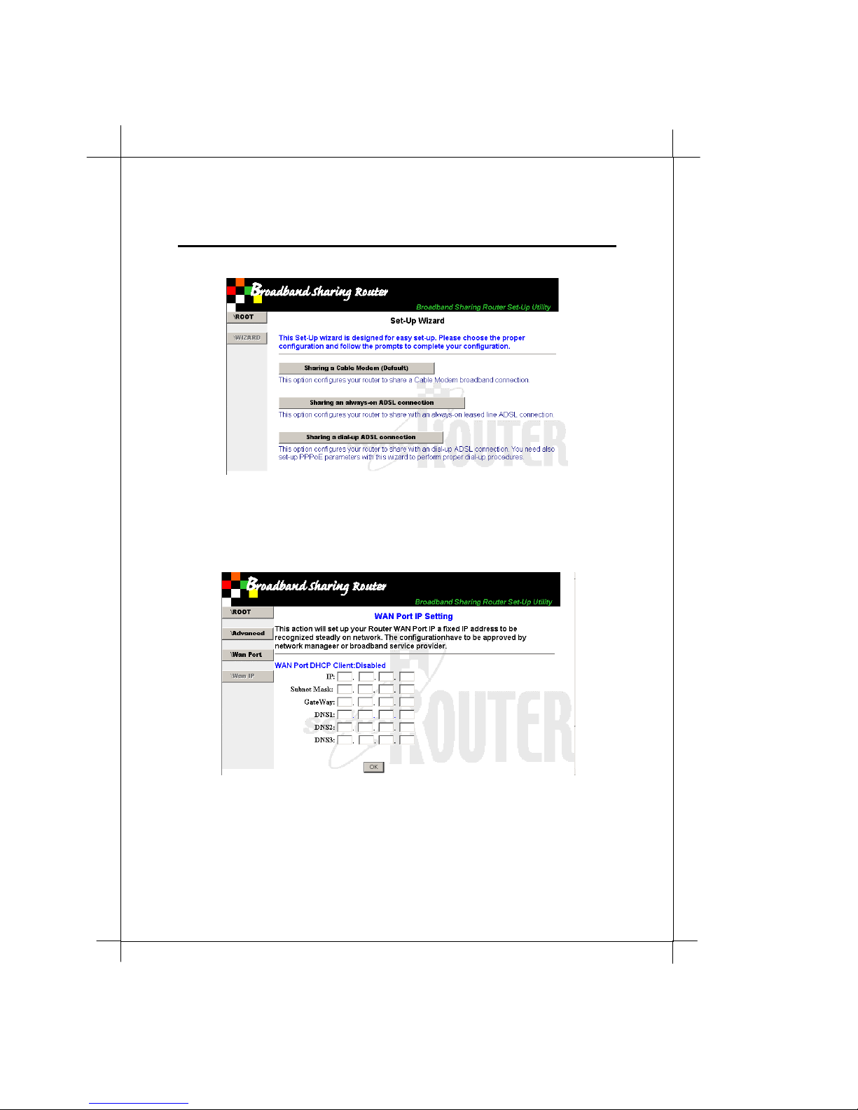
4. Click on
Sharing a n always-on ADSL connection
Syste m Configuration
5. Enter the IP add ress, Subnet Mask, Gateway, and DNS provided
by your NSP. Using TAB key or mouse pointer to move the
cursor between cells. Y ou can ch oose to set one, two, or three
DNS information and leave those cells not us ed in blank.
6. Double confirm the conf iguration. C lick OK to accept this
configuration, any other button to cancel this setup.
Page 31
7
Heritage Series ADSL B ridge/ Router
3.4.3 Sharing a dial up ADSL connection
Syste m Configuration
2
Dial up ADSL (PPPoE, Point- to-Point Protocol over E therne t) is a cost
effective and popular broadband connection. Although the ADSL circuit is
always attached and don’t need to dial numbers to make the circuit
connected. The dial up ADSL use the log in/ log out to active/ inactive the
data communication and counting the communication fee.
To properly set up this ADSL network, the Broadban d Sharing Router
should configure its log in information and auto-discon nect setting in
WAN port configuration. Auto-disconnect time means the connection will
be disconnected utomatically if there’s no data transmission in a certain
amount of time in seconds.
1. Running your browser and go URL:
access the system configuration server.
2. Enter system configuration password. (The default password is
“admin” case sensitive. For security reason , please do change the
password from factory default immediately to prevent
unauthorized change of Router settings.)
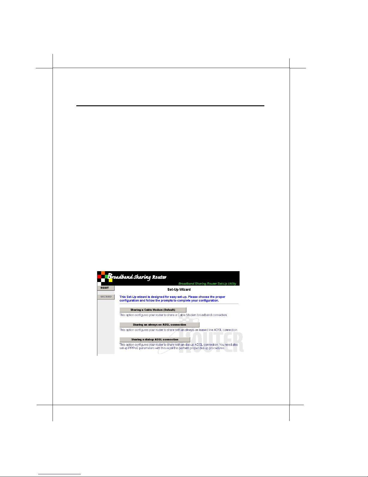
3. Click on
4. Click on
Set-Up Wizard
Sharing a dial-up ADSL connection
“http://192.168.100.1”
to
Page 32
28
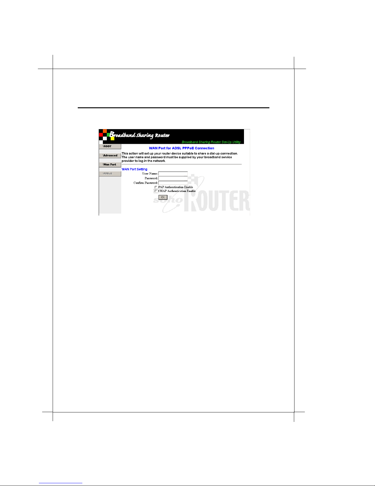
5. Enter your account information and check
and/or
6. Double confirm the conf iguration. C lick OK to accept this
configuration, any other button to cancel this setup.
CHAP authe n tica tion
Syste m Configuration
PAP authentication
as your NSP indicated.
Page 33

Heritage Series ADSL B ridge/ Router
3.4.4 Compart your network
Syste m Configuration
29
Your RT710 Broadband Sharing Router is also a LAN-to-LAN Router. You
can use it to segment networks for better network traffic and security.
Before you attach the RT710 Broadband Sharing Router on to a corporate
network, please be sure you got the permission and appropriate
configuration information from network administrator. Inadequate
network set up may paralize your corporate network.
The easiest way to add a private network on a corporate network is using
DHCP service. If you r corporate ne twork equipped with DHCP server, y ou
can simply configure your RT710 Broadband Sharing Router to factory
default configuration (the same as to share a Cable Modem) and it’s done.
Page 34
0
3
Syste m Configuration
3.5 Advanced Configuration
Your RT710 Broadband Sharing Router is a featured intellgient Router. You
can have more detailed and advanced configurations and make you r
network more efficient. Beside the simple IP routing function, this Router
also provide IP masqu rade and firewall (filtering) functions.
3.5.1 Device Information
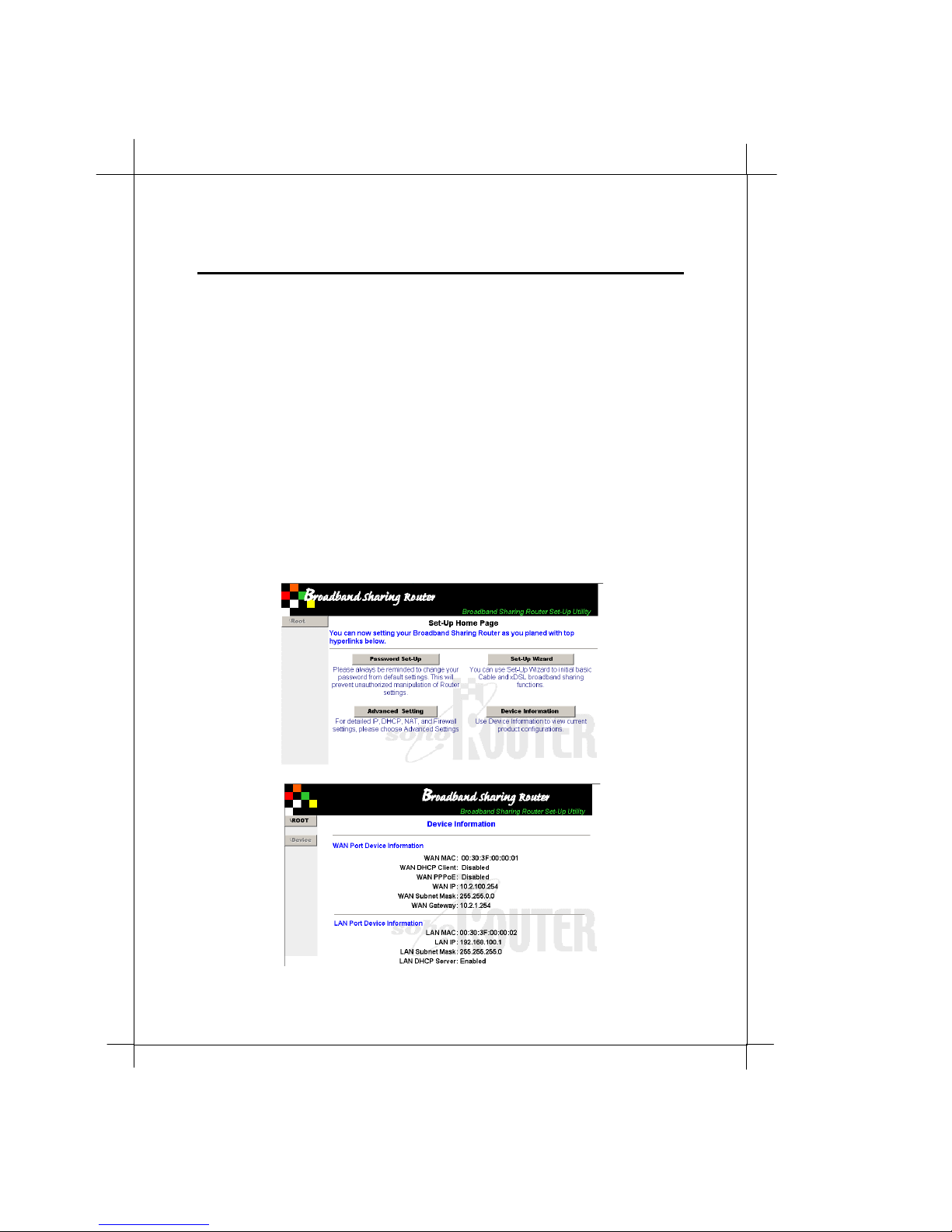
Before you configure your Router, you need to know the current Router
configurations. It’s simple. You can find the latest device information from
the configuration server. Just click th e
configuration home page and all basic configurations are listed.
Device In formation
on
Page 35
Heritage Series ADSL B ridge/ Router
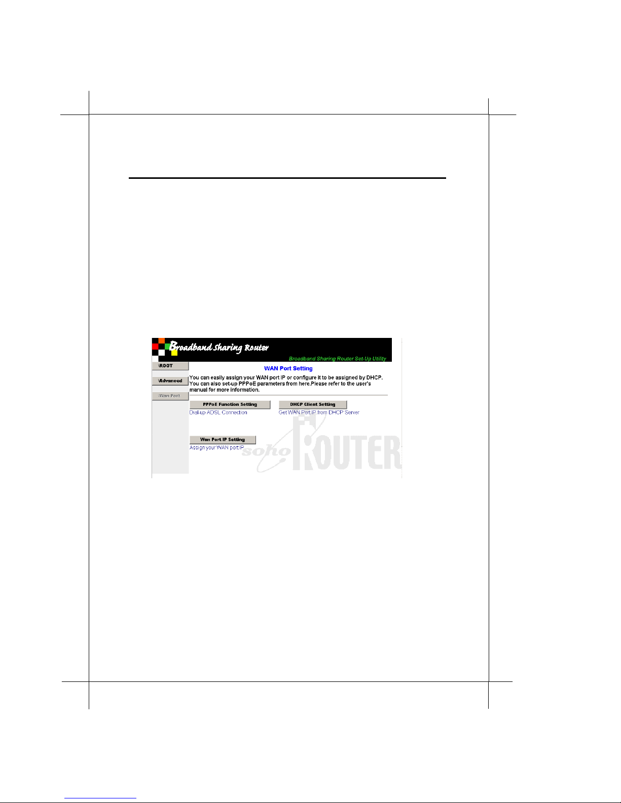
3.5.2 WAN port setting
Syste m Configuration
You can change the WAN port settings without modifying other
configurations.
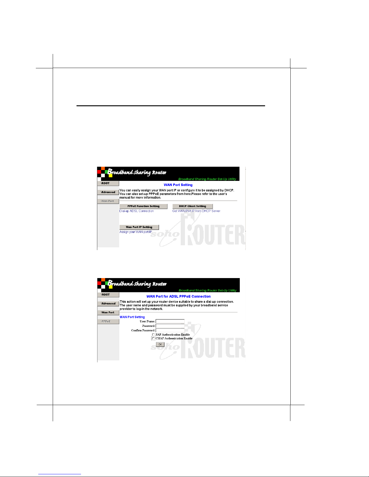
PPPoE Fu nctio n Settin g.
1.
mostly apply to ADSL dial up network.
DHCP Client S etting.
2.
get IP dynamically. Using when connect to Cable Modem or
Ethernet network.
WAN Port IP Setting .
3.
required when your local PCs provide services.
Set up the PPPoE connection, which
Set the WAN port as a DHCP client and
Assign WAN port a fixed IP address. It is
31
Page 36
2
3
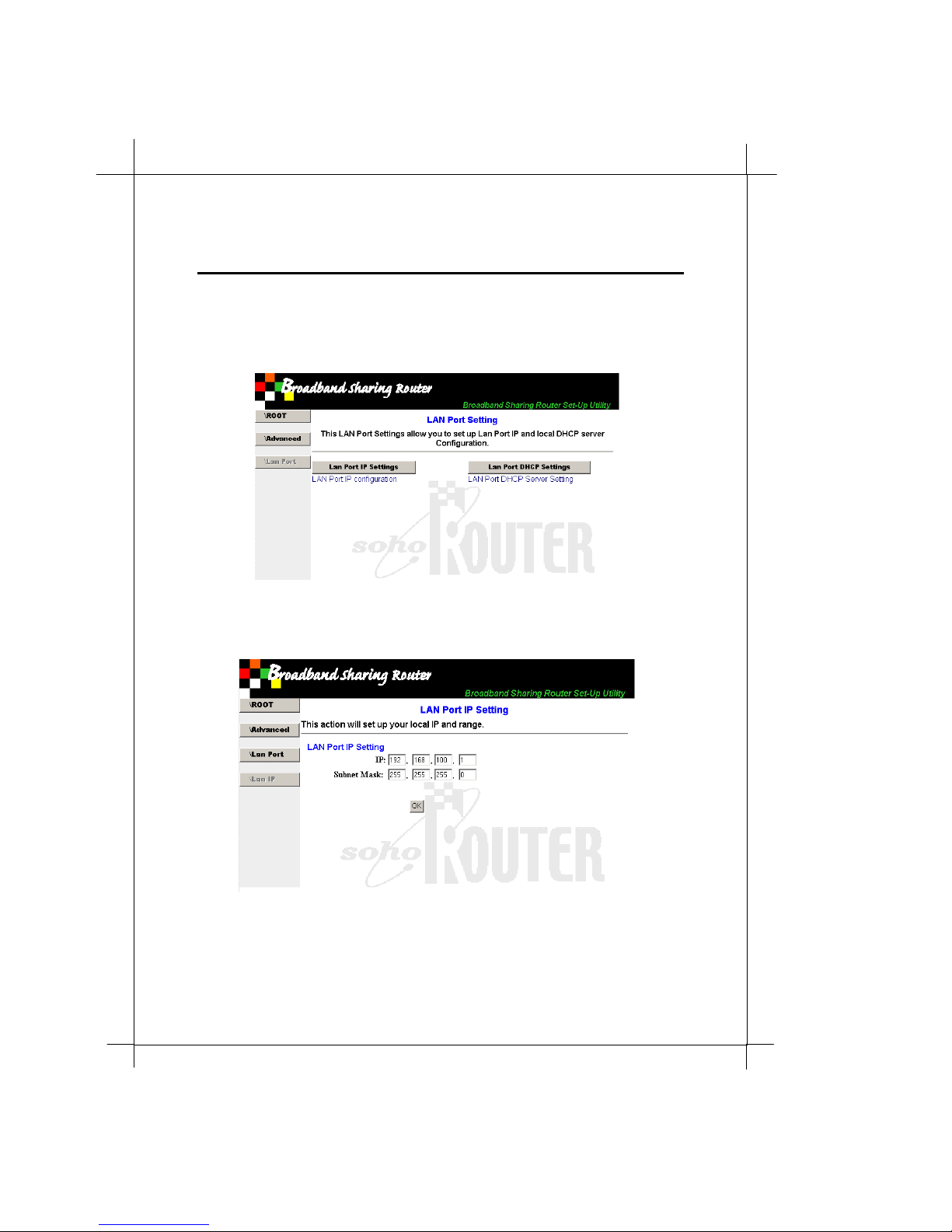
3.5.3 LAN port setting
Syste m Configuration
You can change the LAN port settings without modifying other
configurations.
LAN IP Setting.
1.
PPPoE connection, which mostly apply to ADSL dial up network.
Assign a range of IPs for local PCs. Set up the
Page 37
Heritage Series ADSL B ridge/ Router
IP:
This is also the IP of configuration server and Router gateway
Syste m Configuration
33
Attention: If you change the LAN IP and click OK. The Router IP will be
updated as new IP. If the IP of your PC is out of LAN IP range, please
renew your dynamic assigned or fixed IP. Use the new IP to operate further
configurations after confirms the LAN IP change.
Subnet Mask:
This value specif i e s the to tal ava il able LAN po r t IP
range. You have to make sure your PC is located in this IP ran ge
for further configuration.
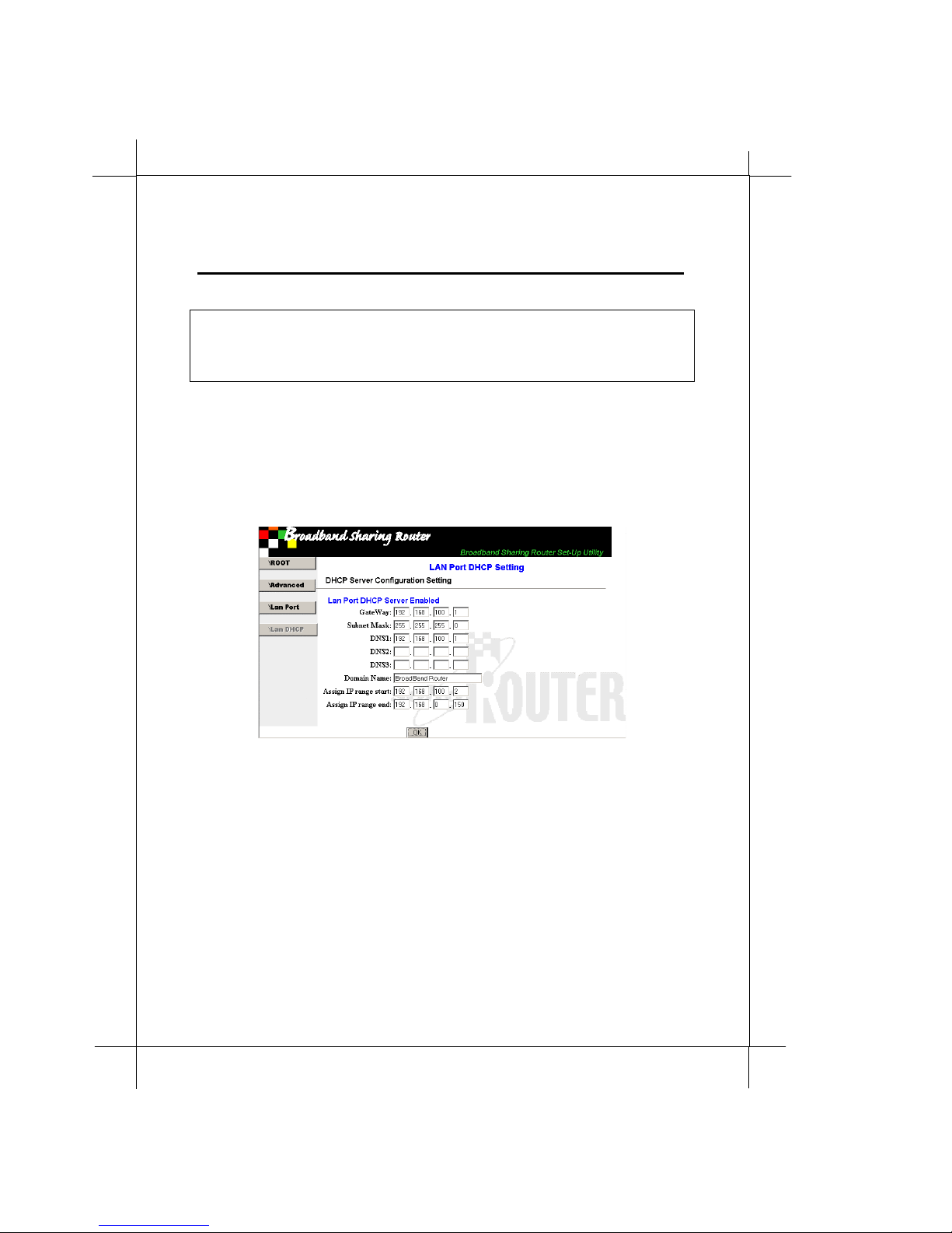
LAN Port DHCP Server Setting.
2.
Set the LA N port as a DHCP
server and assign IPs dynamically.
Gateway:
This is also the IP of configuration server and Router
gateway
Subnet Mask:
Specify the subnet range. When a DHCP client
requests an IP, the DHCP server will apply this setting to clie nt
specifying the subnet range.
DNS:
When a DHCP client requests an IP, the DHCP server will
apply this setting to client specifying the subnet range.
Doma in Name:
Assign IP range start/end:
Specify the name of your network domain.
Specifies the IP range that DHCP
server can issue. The number should cover the total number of
the group, which will be served by the Router.
Page 38
4
3
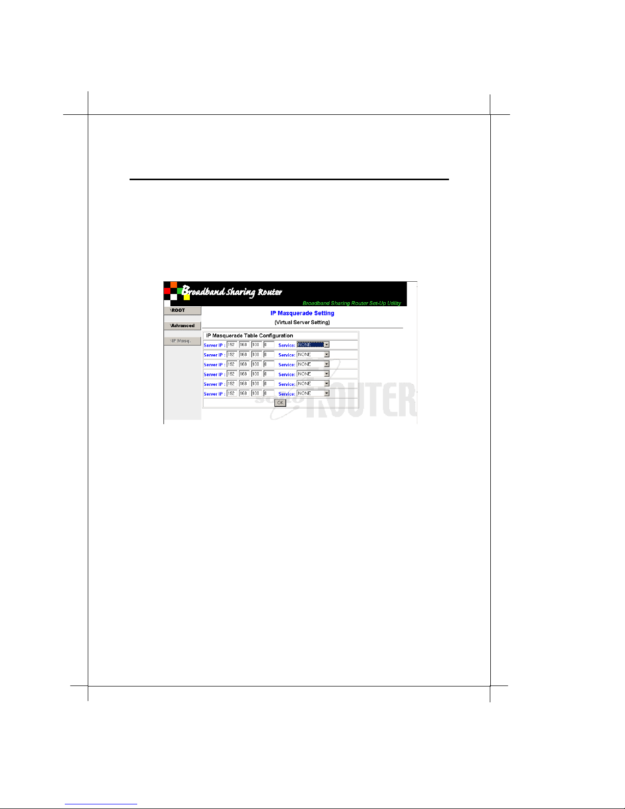
3.5.4 IP masqurade setting
Syste m Configuration
IP masqurade is a key featu re in IP sharing. You can relay many remote or
local services through a single WAN IP.
IP Masqurade Table Configuration.
ports to dif fe ren t local IP s .
Service IP:
Service:
The IP where the service provided.
The related WAN IP port.
Relating different WAN IP
Page 39
Heritage Series ADSL B ridge/ Router
3.5.5 Firew all setting
Syste m Configuration
35
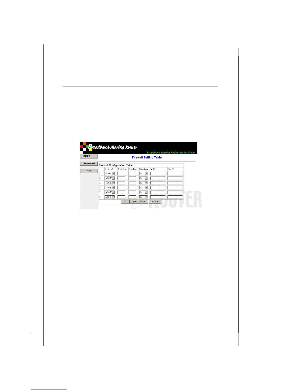
The RT710 Broband Sharing Router featured the packet filtering firewall
function. You can easily enable/disable packet traffic whatever you want.
Firewall Config ura tion Table.
allows you to setup more than 6 packet-filtering rules. Use the
page navigation buttons to view all the rules.
Protocol:
Start Port and End Port:
Direction:
In IP:
Out IP:
Which IP pa cket pr otocol t ype.
Where packets going in or going out.
Filte ring re quest from specif ic I P.
Filte rin g spe cifi c serv ice d es tination IP
This packet filtering firewall
Going through which WAN I P port.
Page 40
6
3
3.5.6 Firmware upgrade
Syste m Configuration
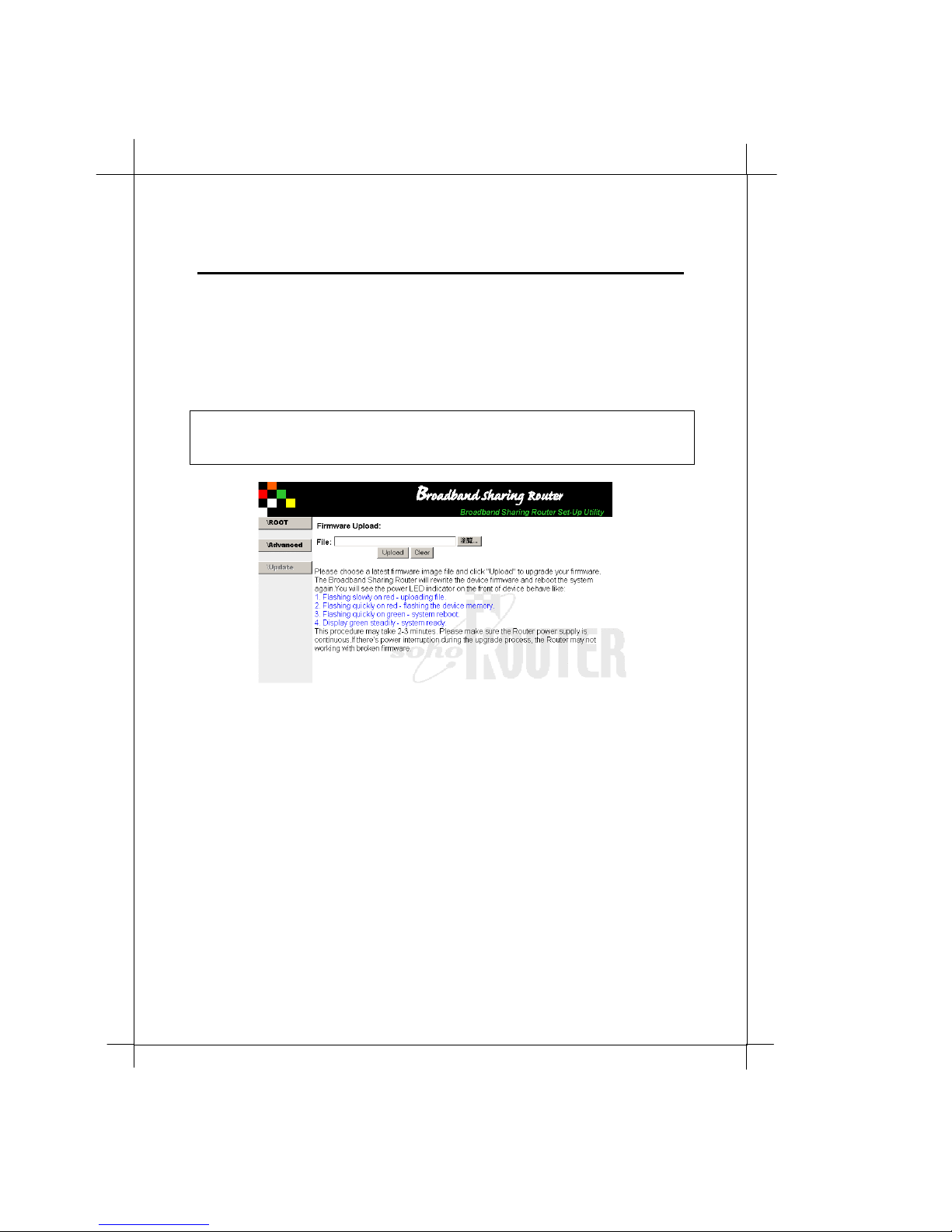
The RT710 Broband Sharin g Router i s a fi r m war e upgradeable device . Ne w
firmware will be updated with adding features after a while. You can get
your latest firmware from your dealer or service web site and feature your
Router as a featured device.
Attention: The firmware upgrade process is very critical. Please make sure
the upgrade process will not be interrupted. Otherwise, your Router can be
dead with if the firmware is brocken.
1. Down load and make sure the firmware image file is OK.
2. Locate the place of image file.
3. Click Upload to stare the upgrade process. And do not interupt
the upgrade process. You can check with PWR/CHK LED to
moniter the t otal process.
i. F lashing slowly on red – uploading file
ii. Flashing quick ly on red – wri ting the device memory
iii. Flashing quick ly on green – s yste m boot-up
iv. Display green steadly – system ready
Page 41
7
Heritage Series ADSL B ridge/ Router
3.5.7 PPPoE setting
Syste m Configuration
3
PPPoE setup
When you want to connect or disconnect RT710 Broband Sharing Router
PPPoE service (dial up ADSL). You can:
Advanced Settin g
1. go
2. Enter your account information and check
and/or
CHAP authe n tica tion
PPPoE Fu nctio n Settin g
!
as your service provid er indicated.
.
PAP authentication
Page 42
38
Syste m Configuration
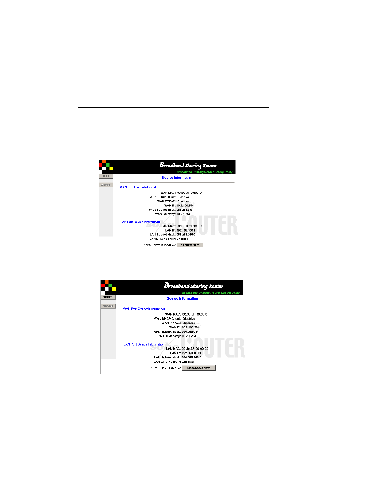
PPPoE connect/disconnect
When you want to make PP PoE connection. Please go Home !
Device Information. If your PPPoE is p roperly set up, y ou can s ee
the connecting/disconnecting button on the last line of Device
Information page.
To disconnect PPPoE, just click the disconnect button on Dev ice
Information page.
Page 43

Heritage Series ADSL B ridge/ Router
Appendix
Appendix A Glossary
10Base-T
IEEE 802.3 standard for the use of Ethernet LAN technology over
unshielded twisted pair wiring, running at 10Mbps.
100Base-T
IEEE 802.3 standard for the use of Ethernet LAN technology over
unshielded twisted pair wiring, running at 100Mbps.
ADSL
Asymmetri c Dig ita l Sub s crib e r Lin e - T ech n olog y t ha t d eliv e rs
high-speed data and v oice connections over existing phone lines. Up
to 8 Mbits/sec can be sent downstream and 640 Mbits/sec upstream.
ANSI (American National Standards Institute)
Devises an d propos e s recommen da t ions for int e rna tion al
communications standards.
ARP
Address Resolution Protocol. An Internet protocol used to bind an I P
address to Ethernet/802.3 addresses.
ASCII
American Standard Code for Information In tercha nge. 8-bit code for
character representation.
CHAP
Challenge Handshake Authentication Protocol. A security protocol
support ed unde r Poin t -t o-P oin t Prot ocol (PPP) us ed to prev en t
unauthorized access to devices and remote netwo r ks. Uses encrypti o n
of password, device names, and random number generation.
A1
Page 44

2
A
Class A, B, and C networks:
The values assigned to the first few bits in an IP network address
determine which class designation the network has. In decimal
notation, Class A n etwork addresses range from 1.X.X.X to 126.X.X.X,
Class B network addresses range from 128.1.X.X to 191.254.X.X, and
Class C addresses range from 192.0.1.X to 223.255.254.X.
Client
An intelligent workstat ion that make s requ ests to other computers
known as servers. PC computers on a LAN can be clients.
DHCP
Dynamic Host Configuration Prot ocol - Service that provid es network
information (such as IP addresses, masks, domain names) to PCs and
other clients automatically .
DNS
Domain Name Service - Transmission Control Protocol/Inte rnet
Protocol (T CP / I P) se rvice wh ich tran s lat es a na me th a t a pe rson can
remember into an IP address that a computer can use.
DTE
Data Terminal Equipment - Term defined by standards a committee,
that applies to communications equipment, typically personal
computers or data terminals, as distinct from other devices that attach
to the network, typically modems.
Ethernet address
Sometimes re ferred to as a hardware add ress. A 48-bits long number
assigned to every Ethernet hardware device. Ethernet addresses are
usually expressed as 12-character hexadecimal numbers, where each
hexadecimal character (0 through F) represe nts four binary bits. Do
not confuse the Ethernet ad dress of a device w ith its ne t w ork add ress.
Firmware
System software stored in a device’s memory that controls the device.
Internet
A set of networks connected together by routers. This is a general
term, not to be confused with the large, multi-organizational
collection of IP net works known as the Internet . An Internet is
sometimes also known as an internetwork.
Appendix
Page 45

Heritage Series ADSL B ridge/ Router
Internet address, IP address
Any computing device that uses the Internet P rotocol (IP) must be
ass igned an in te rn et or IP ad d re ss . Th is is a 32-b it n u mb er as sig n e d
by the sy stem administrator, usually written in the form of 4 decimal
fields separated by periods, e.g., 192.9.200.1. Part of the internet
address is the IP network number (IP network address), and part is
the host address (IP host address). All machines on a given IP
network use the same IP network number, and each machine has a
unique IP host address. The system administrator sets the subnet
mask to specify how much of the address is network number and
how much is host address.
IP
Inte rnet Protocol - A networking protocol developed for use on
computer systems that use the UNIX operating system. Often used
with Ethernet cabling systems. In this manual, IP is used as an
umbre lla term to cove r all pack et s and net work i ng operations th a t
include the use of the Internet Protocol. See also
ISP
Internet service provider - A company that provides Internet-related
services. Most importantly, an ISP provides Internet access services
and products to other compa nies a nd consumer s.
ITU
International Telecommunication Union - United Nations specialized
agency for telecommunications
LAN
Local area network - A privately owned network that offers
high-speed communications channels to connect information
processing equipment in a limited geographic area. (usually within a
single campus or building).
LED
Light Emitting Diodes - Type of indicator lights on the panel of the
router.
MAC layer/address
Media Access Control layer/address defined by the IEEE 802.3
specif ications, which define s media access in cludin g framing and
error detection. Part of the OSI referen ce model data link layer.
MIB
Management information; base on a standardized struct ure for SNMP
manag eme n t in f ormati on .
Appendix
TCP/I
P.
A3
Page 46

4
A
MDI/MDIX (Media Dependence Interface – Straigh t-through/Crossove r)
The IEEE 10Base-T standard for the UTP cable interface. The MDI
(straight-through) mode is usually configured to connect to network
terminal equipment, such as a PC. The MDIX mode is usually
configured to connect/uplink to another network equipment, such as
a cable modem, ADSL or HUB.
MDI/MDIX autodetect feature eliminates typical concerns about
crossove r cabling, limite d uplinks, or to which dev ices a sw itch is
linked. The ports automatically sense if they need to function as
straight or crossover ports, thus crossover cables can con nect both
PCs and switches or hubs.
MSO
Multimedia System Operator – the term indicate the entetity who
provide multiple services including, broadband data service, on CATV
cable n et work . Usu a lly in d icat e d as a cab le operat or.
NAT
Network Address Translation - A feature that allows communication
between the LAN connected to the Modem and the Internet using a
single IP address, instead of having a separate IP address for each
computer on the network.
NSP
Network Service Provider - Company from which you buy your
network services.
PAP
PPP Authentication Protocol - A method for en suring secure network
access.
Ping
An echo message, available within the TCP/IP protocol suite, sent to
a remote node and returned; used to test the accessibility of the
remote node .
Port number
A number that identifies a TCP/IP-based service. Telnet, for exam p l e,
is identified with TCP port 23.
Protocol
A set of rules for communica tion, so metimes made up of several
smaller sets of rules also called protocols.
Appendix
Page 47

Heritage Series ADSL B ridge/ Router
PPP
Point-to-Point Protocol - A Data Link layer protocol t hat provides
asynchronous and synchronous connectivity between
computer/network nodes. It defines how packets of information are
exchanged between computers or network nodes connect via a
point-to-point connect ion (as opposed to multipoin t or broadcast).
Includes standardization for security and compression negotiation .
RFC
Request for Comment - A series of documents used to exchange
information and standards about the Internet.
RJ-45
A telep hone-industry s tandard connect or type , usually containing
eight pins.
Routing
A network layer function that determines the path for transmitting
packets through a network from source to destination.
Router
A device that supports network communications. A router can
connect identical network types, however—unless a gateway is
avail able—a common protocol, su ch as TCP/IP, must be used over
both networks. Routers may be equipped to provide WAN line
support to the LAN devices they serve. They may also provide
various mana gement and monitoring functions as wel l as a v ariety of
configuration capabilities.
Routing table
A list of networks maintained by each router on an Internet.
Information in the routing table helps the router determine the next
router to forward packets to.
Server
A device or system that has been specifically configured to provide a
service, usually to a group of clients.
Subnet
A network address created by using a subnet mask to specify that a
number of bits in an internet address will be used as a subnet number
rather than a host address.
Appendix
A5
Page 48

6
A
Subnet Address
An extension of the Internet 32-bit addressing scheme which allows
the separation of physical or logical networks within the single
network number. assigned to an organization. TCP/IP entities
outside this organization have no knowledge of the internal
‘subnetting’.
Subnet mask
A 32-bit number to specify which part of an internet address is the
network number, and which part is the host address. When written in
binary notation, each bit written as 1 corresponds to 1 bit of network
address information. One subnet mask applies to all IP devices on an
indi vid u a l IP n e tw ork.
TCP/IP
Transmission Control P rotocol/Internet P rotocol - An open network
standa rd that defines how devices from different manufacturers
communicate with each other over one or more interconnected
networks. TCP/IP protocols are the foundation of the Internet, a
worldwid e networ k of netw orks connecting busi nesses, gover nments,
researchers, and educators. TCP provides a connection-oriented
transport layer ensuring end-to-end reliabil ity in data transmissio n. IP
provides for network layer connectivity using connectionless
datagrams.
TFTP
Trivial File Transfer Protocol - A protocol used t o trans fe r file s
between IP nodes. TFTP is often used to transfer firmware and
configuration information from a UNIX computer acting as a TFTP
server to an IP networking device.
TELNET
Internet standard protocol for remote terminal emu lation t hat allows
a u ser to remot ely log in to another device and appear as if directly
connected.
UDP
User Datagram Protocol - A TCP/IP pr otocol describing how packets
reach applications in destination nodes.
Wall jack
A small hardwa re component used to tap into telephone wall cable.
An RJ-11 wall jack usua lly has four pins; an RJ-45 wall jack usually
has eight pins.
Appendix
Page 49

Heritage Series ADSL B ridge/ Router
WAN
Wide Area Network - A network that consists of nodes
connected by long-distance transmission media, such as telephone
lines. WANs can span a state, a country, or even the world.
Appendix
A7
Page 50

A8
Appendix
Appendix B Product
Specifications
WAN Interface
Connector: 8 pin modular (RJ-45)
LAN Interface
Human In t e rfa ce Switch: Factory
LED Indicator: PWR/CHK, Lin k/Active status,
Network Functions
Port: 1 port ( MDI X)
Interface: IEEE 802.3u (10/100Base-T)
Port: 4 ports (MDI/MDIX auto detect X 4)
Interface: IEEE 802.3u (10/100Base-T)
Connector: 8 pin modular (RJ-45)
DEFAULT
Link speed (100Base-T)
Protocol
DHCP: RFC1541 (Client and Server Function)
•
IP: RFC791
•
ARP: RFC826
•
UDP: RFC768
•
TCP: RF C7 93
•
RIP: RFC 1058
•
PPP: PP PoE support for ADSL
•
NAT/IP Masqurade
•
reset button
Page 51

Heritage Series ADSL B ridge/ Router
EMC Emission FCC part 15, class B
Power Power input: 9VAC/ 1500mA
Mechanical Size: 228mm(width) x 143mm (depth) x 30mm
Net Weight: 800 g
Environmental Operating temperature:
Humidity: 25 % ~ 85 % (non-condensing)
Storage temperature: -20°C ~ 60°C
Appendix
Networking Management
•
Web based configuration through Ethernet
interfaces
•
Syslog for recordin g connection log
•
Teln et and TFTP for firmware update and
configuration file backup and restore
Firewall: Packet Filtering and Port Filtering for
controlled access to and from your network
(height)
0°C ~ 40°C
A9
Power Adaptor
The RT710 Broadband Sharing Router is powered by a 9V/1.5A AC power
adaptor, which included in this package. In any case the standard power
adaptor come with this package is not available, please find a power
adaptor meet above specifications.
Page 52

0
A1
Appendix
Appendix C Troubleshooting
This chapter is intended to help y ou troubleshoot problems you may
encounter while setting up and using the Router. It also describes some
common hardware and software problems and gives some suggestions to
troub leshoot them.
C.1 Diagnostics with the LEDs
Most hardware problems can be diagnosed and solved by checking the
LEDs on the front panel of your Router.
If the PWR/CHK L E D is dark
!"
- Make sure the pow er cord is firmly plugged into the back pan el
of the router and the other end into an active AC wall or power
strip outlet .
If the LAN or WAN port LINK/ACT LED is dark
!"
- Ma ke su re your E thernet cable is firmly plugged into the back
panel of the router and the other end into your computer or
HUB.
- Make sure you using the correct Ethernet cable on WAN port fo r
your application.
- Make sure your Ethernet board is installed properly in your
system by ping the IP add ress of your PC.
Page 53

Heritage Series ADSL B ridge/ Router
Appendix
C.2 No respond or active data
No respond from system configuration server
!"
- Make sure your URL is correct and not conflict with any other
device on net work. The factory defa ult URL is
“http://192.168.100.1 “. You cannot recall any page or
budirectory without password verification. Please do not add
any parameter after the IP address. If you changed the LAN IP
address, please use the new system configuration server IP you
changed. If you forget the IP you changed, you can only reset
the configuration to factory default to setup your Router again.
Please refer
know how to reset the Router configuration to factory default.
- Make sure you are accessing the configuration server through
LAN ports. The configuration server can only be accessed
through LAN ports, not from WAN port.
- Make sure your configuration PC is in the sa me subnet which
LAN port setup specified or your IP is getting from Router
DHCP. Please use IP configuration check to verify your PC’s IP
address.
- Make sure your LAN port connection is linked and active
correctly.
Data link is brocken
!"
- If your network is configured correctly, you can share and
connect different computers. If the data cannot be accesses
through the Router, restart your Router with unplug the power
cord. Wait for a while and plug in the power again. The system
needs one to two minutes to boot itself up. Please wait until the
PWR/CHK LED light steadly and then keep going for further
operation.
- Make sure that all devices IPs connected with LAN port, direct
connect or through HUBs, should follow the rule of LAN port
configuration. Gateway IP is the same as system configuration
server and cannot be used by any other device.
3.1 Get your Broadband Sharing Router ready
A11
to
Page 54

2
A1
Appendix
C.3 Contact us for Technical support
We are committed to providing our customers with reliable products
and documentation, backed by excellent technical support.
Before contacting u s, please l
problem. You may find a solu tion in this ch apter. If you cannot find a
solution, collec t your conf iguration information listed below b efore
contacting our techn ical support. We can help you wit h your problem
more effe ctively if you have comple ted the configuration information.
Model number:
Serial (MAC) number:
Firmware ve rsion :
PC configuration
Network configuration
Other:
ook in this chapter for a solution to your
Page 55

Heritage Series ADSL B ridge/ Router
Appendix
A13
Appendix D Government
compliance notices
D.1 FCC compliance
This Broadband Sharing Router has been tested and found to comply with
the limits for a Class B personal computer and peripherals, pursuant to Part
15 of the FCC Rules. These limits are designed to provide reasonable
protecti on against harmful interference in a resid ential insta llation. This
equipment generates, uses and can radiate radio frequency energy and , i f
not ins t al led an d u s ed in accord an ce wi t h t he ins tructions , may cause
harmful interference to radio communicat ions. Howe v er, there is no
guarantee that interference will not occur in a particular installation. If this
unit does cause harmful interference to radio or television reception, which
can be determ ined by turning the unit off and on, the user is encouraged to
try to correct the interference by one or more of the following measures:
•
Reorient or relocate the rece iving ante nna.
•
Increase the separation between the equipment and receiver.
•
Connect the equipment into an outlet on a circuit different from that
to which the receiver is connected.
•
Consult the dealer or an experienced radio/TV technician for help.
 Loading...