

Page 1
CAUTION!
PLEASE KEEP POWER
SWITCH ON BEFORE
OPERATING THIS EQUIPMENT
Turbo Air Speed up the Pace of Innovation
Commercial
Refrigerator & Freezer
Service Manual
Please read this manual completely before attempting to install or operate this equipment!
SOLID DOOR
TSR-23SD*
TSR-35SD TSF-35SD
TSR-49SD
TSR-72SD
TSF-23SD
TSF-49SD
TSF-72SD
www.turboairinc.com
Page 2

TABLE OF CONTENTS
1. FEATURE CHART
1-1. FRONT VIEW
1-2. SIDE VIEW
2. WIRING DIAGRAM
2-1. REFRIGERATOR (1DOOR) : TSR-23SD
2-2. FREEZER (1DOOR) : TSF-23SD
2-3. REFRIGERATOR (2DOOR) : TSR-49SD
2-4. FREEZER (2DOOR) : TSF-49SD
2-5. REFRIGERATOR (3DOOR) : TSR-72SD
2-6. FREEZER (3DOOR) : TSF-72SD
3. PART DETAILS
3-1. TOP GRILLE
3-2. REFRIGERATION COMPARTMENT
3-3. ELECTRICAL BOX
3-4. DOOR
3-5. COOLING COMPARTMENT
4. MAIN COMPONENTS
4-1. COMPRESSOR
4-2. COMPRESSOR RELAY
4-3. CONDENSER DRYER
4-4. CAPACITOR
4-5. EVA FAN MOTOR
4-6. CONDENSOR FAN MOTOR
4-7. EVA DEFROST HEATER
4-8. LAMP
4-9. PCB TRANSFORMER
4-10. MAIN PCB
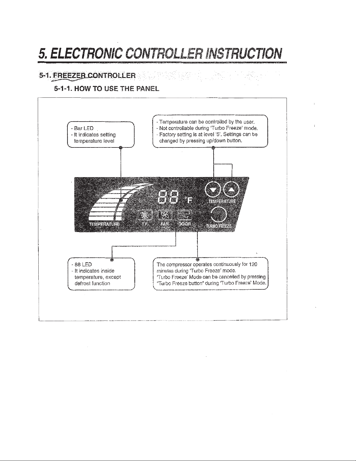
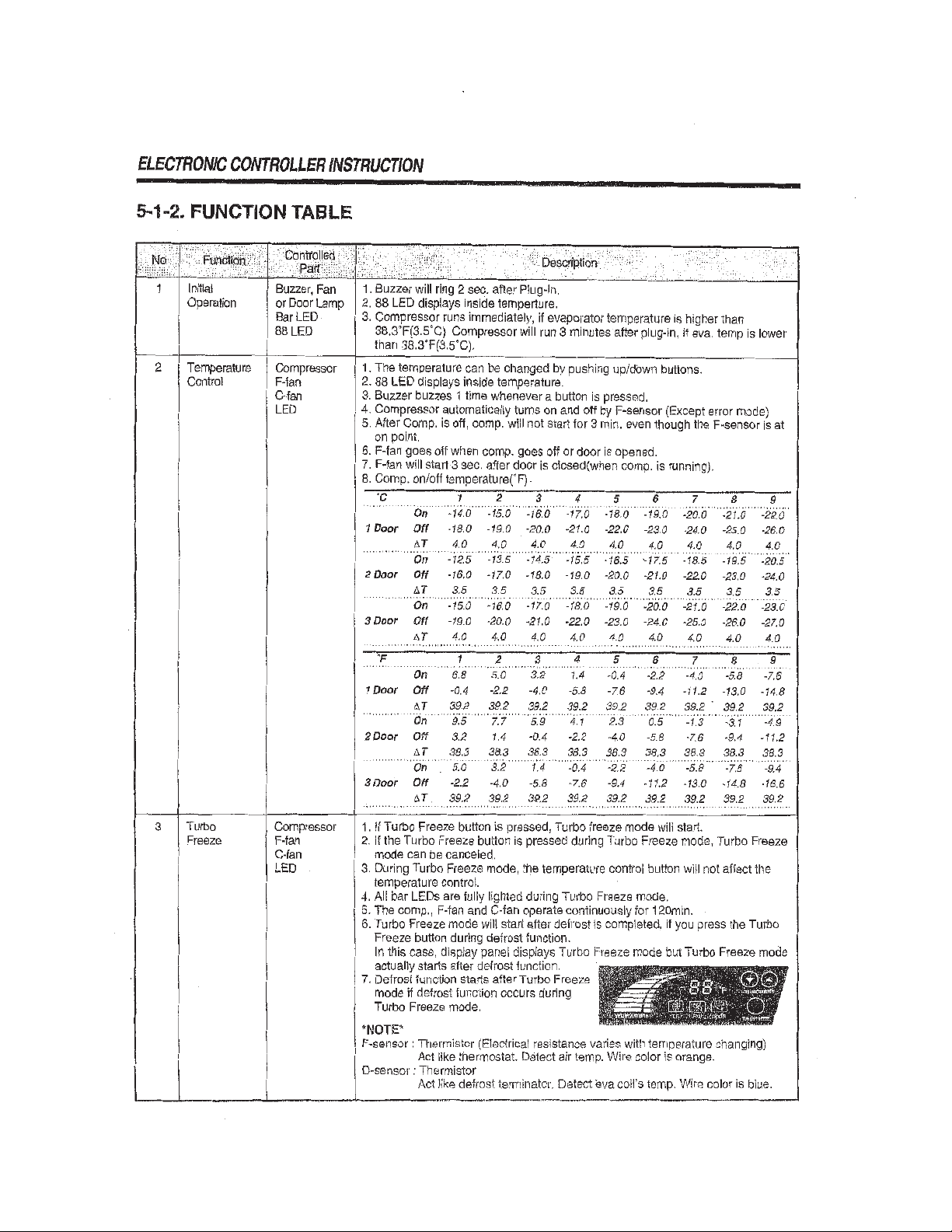
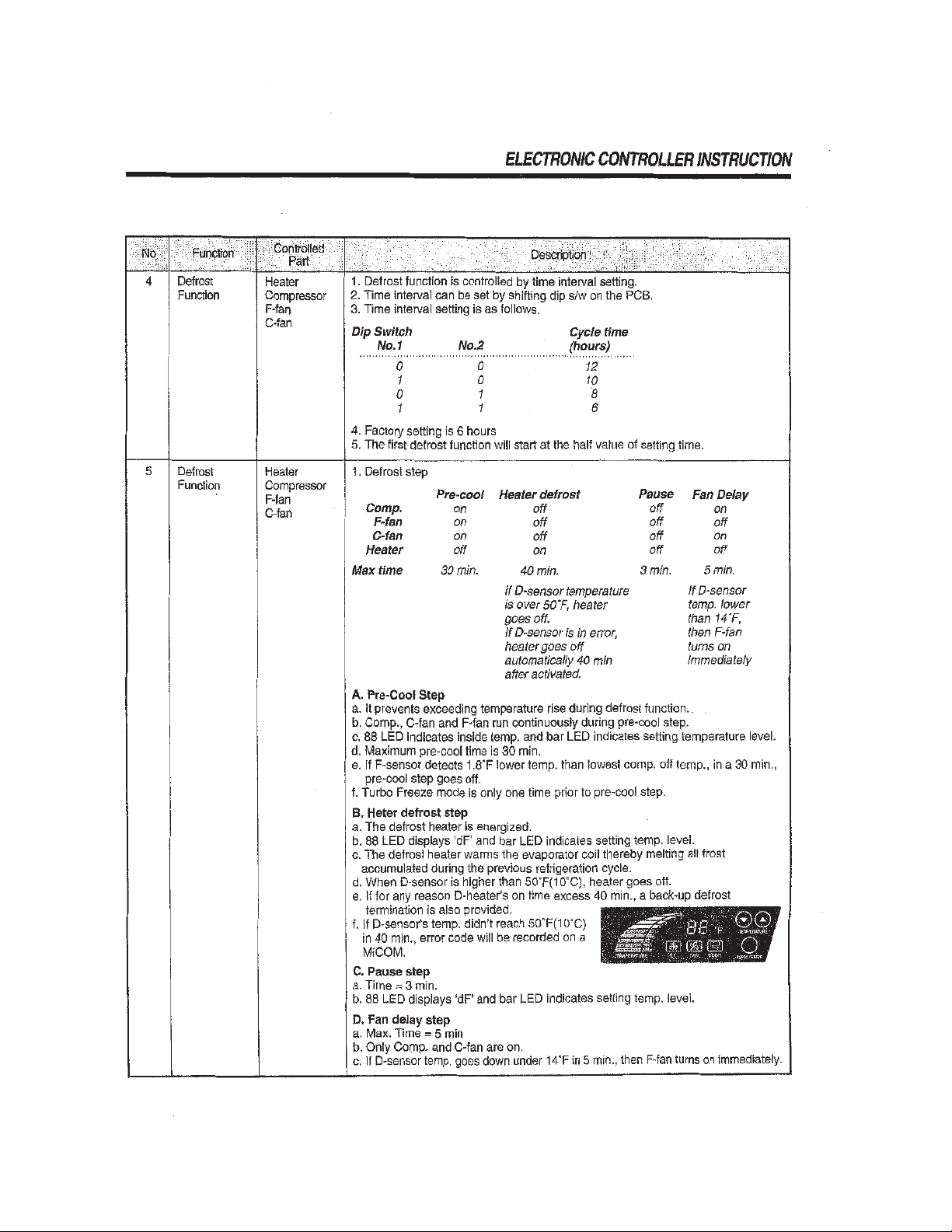
5. ELECTRONIC CONTROLLER INSTRUCTION
5-1. FREEZER CONTROLLER
5-1-1. HOW TO USE THE PANEL
5-1-2. FUNCTION TABLE
5-1-3. ERROR CODE TABLE
5-2. REFRIGERATOR CONTROLLER
5-2-1. HOW TO USE THE PANEL
5-2-2. FUNCTION TABLE
5-2-3. ERROR CODE TABLE
6. SPARE PARTS LIST
7. REPLACEMENT OF MAIN COMPONENTS
7-1. TOP GRILLE PARTS
7-2. REPLACING DOOR
7-3. REFRIGERATION COMPARTMENTʼS PARTS
7-4. CONDENSING UNIT
7-5. REPLACING CABINET FRAME HEATER (AND/OR) MULLION HEATER
Page 3
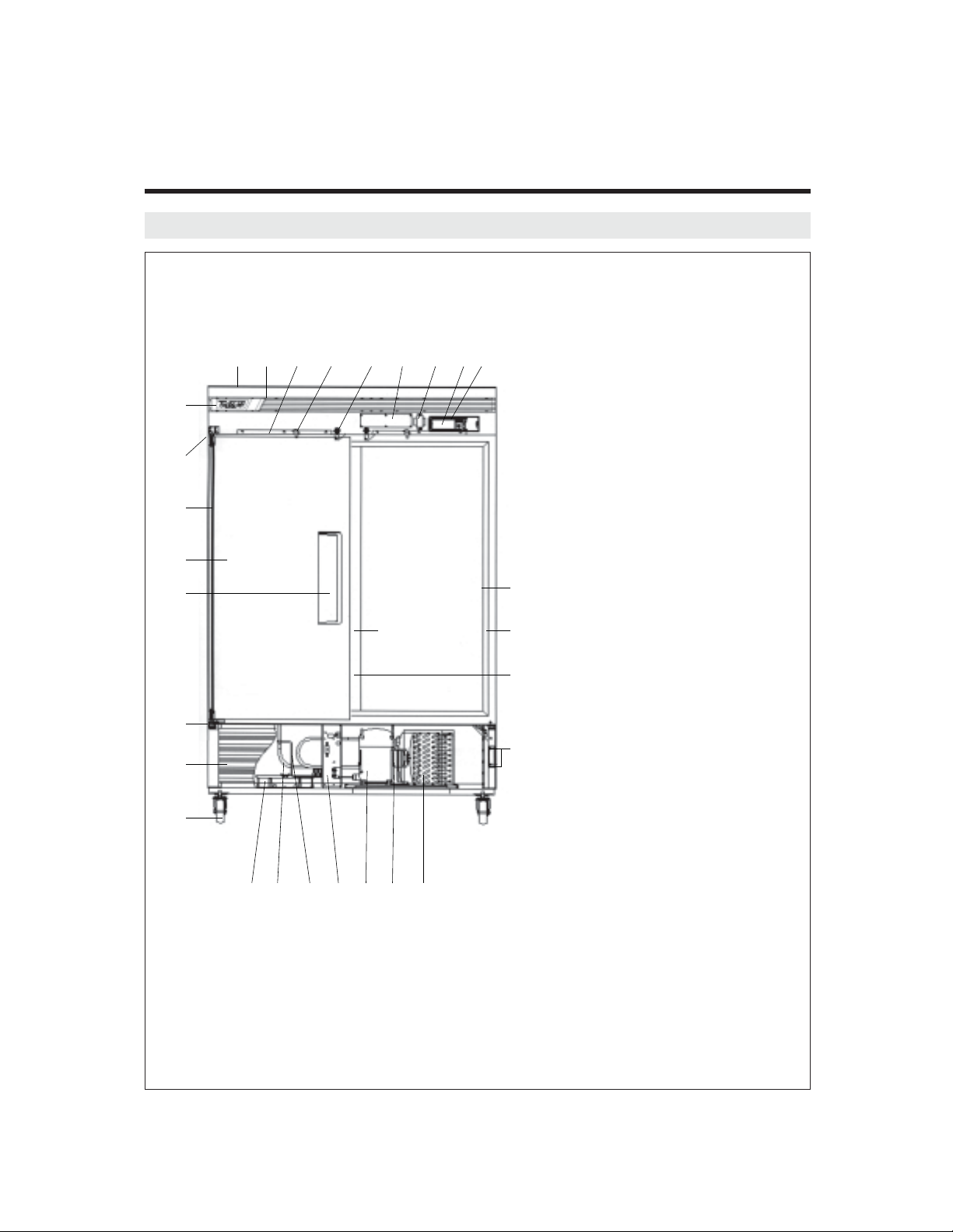
1. FEATURE CHART
1-1. FRONT VIEW
1
23 4 56 789
0
q
w
e
r
j
t
y
u
io pasdf
k
l
h
g
1 TOP GRILLE PANEL
2 TOP GRILLE
3 TOP GRILLE FIXTURE
4 DOOR SWITCH
5 DOOR LOCK
6 MAIN PCB
7 TRANSFORMER
8 DISPLAY PCB
9
CONTROL BOARD HOUSING
10 BRAND LOGO
11
DOOR HINGE TOP ASSEMBLY
12 DOOR HINGE SPRING
13 DOOR ASSEMBLY
14 DOOR HANDLE
15
DOOR HINGE BOTTOM ASSEMBLY
16
BOTTOM GRILLE ASSEMBLY
17 CASTER
18 DRAIN PAN
19 SUCTION PIPE
20 CAPILLARY TUBE
21 ELECTRICAL BOX
22 COMPRESSOR
23
CONDENSER FAN MOTOR
24 CONDENSER COIL
25 GRILLE FIXTURE
26
MULLION (CENTER POST)
27 MULLION HEATER
28 FRAME HEATER
29 FRAME COVER
Page 4
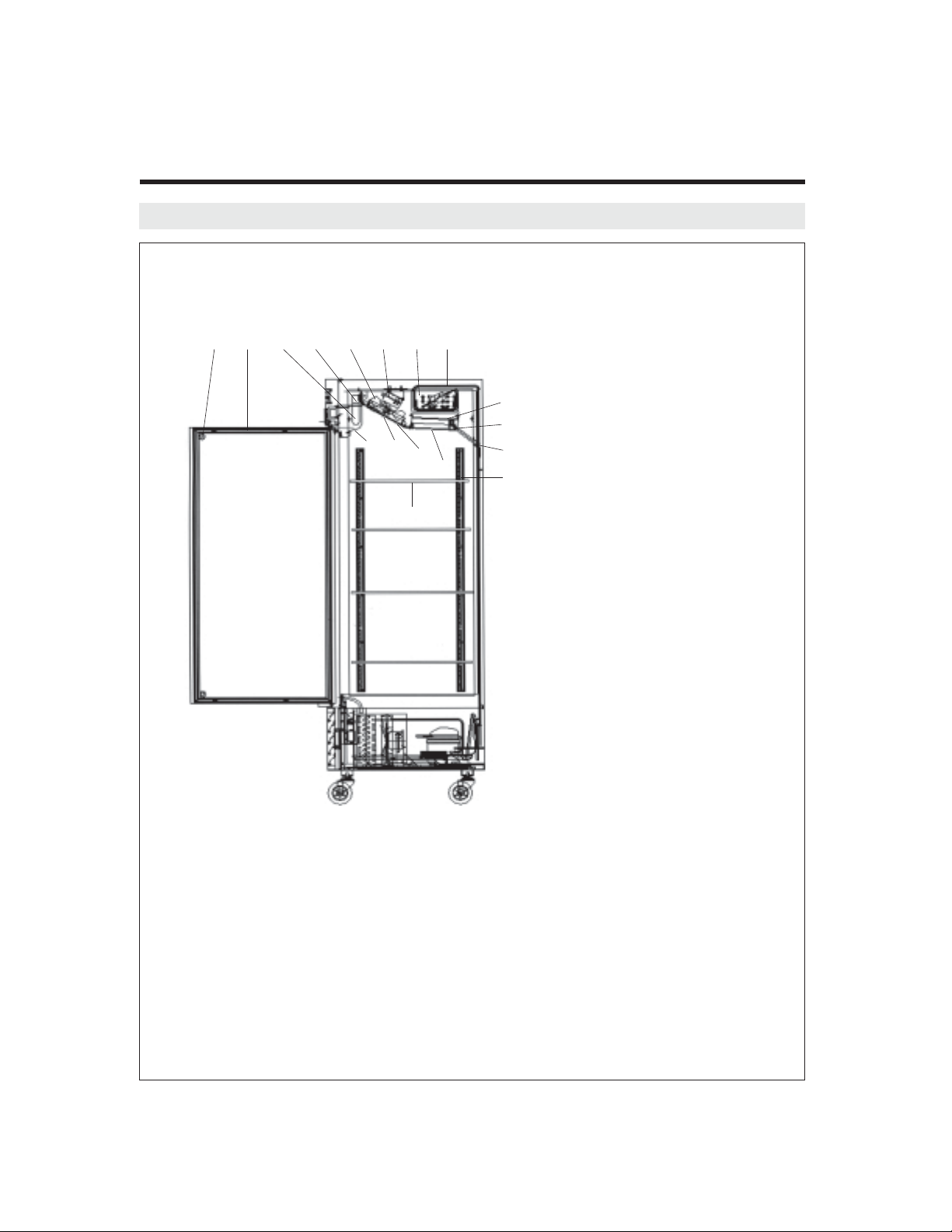
1-2. SIDE VIEW
l;zxcvbn
FEATURE CHART
29 DOOR BUMPER
30 DOOR GASKET
m
31 LAMP BULB
,
!
@
#
$
%
32 LAMP SOCKET
.
33 EVAPORATOR FAN
/
MOTOR BLADE
34
EVAPORATOR FAN MOTOR
35 EVAPORATOR COIL
36 SUCTION PIPE
37
EVAPORATOR DRAIN PAN
38 EVAPORATOR DRAIN
ELBOW
39 DRAIN HOSE
40 SHELF STANDARD
41 LAMP SHIELD
42 EVAPORATOR FAN
MOTOR GUARD
43 DUCT (A) ʻFRONTʼ
44 DUCT (B) ʻBOTTOMʼ
45 SHELF
Page 5
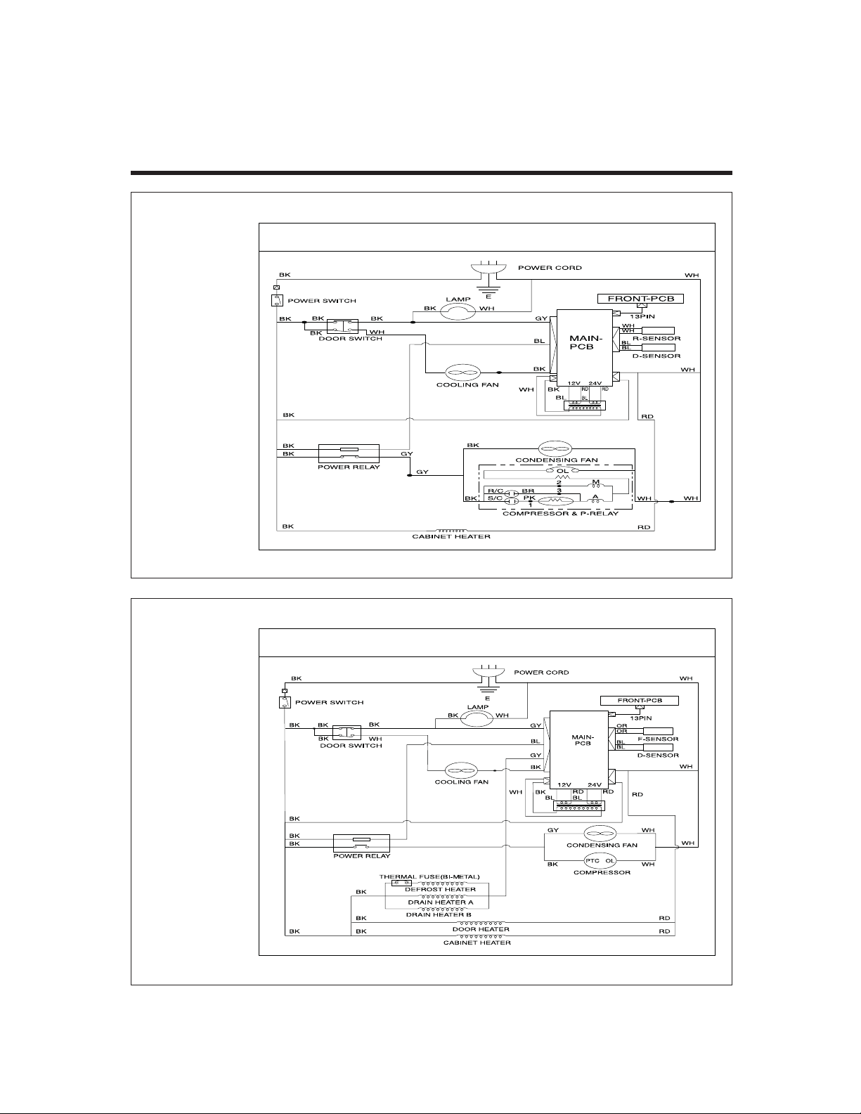
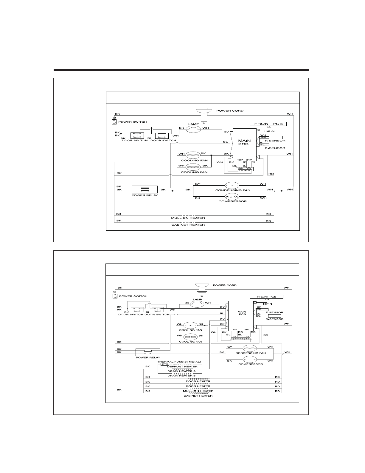
2. WIRING DIAGRAM
2-1. TSR-23SD
WIRING DIAGRAM
2-2. TSF-23SD
WIRING DIAGRAM
Page 6
2-3. TSR-49SD
WIRING DIAGRAM
WIRING DIAGRAM
2-4. TSF-49SD
WIRING DIAGRAM
Page 7
WIRING DIAGRAM
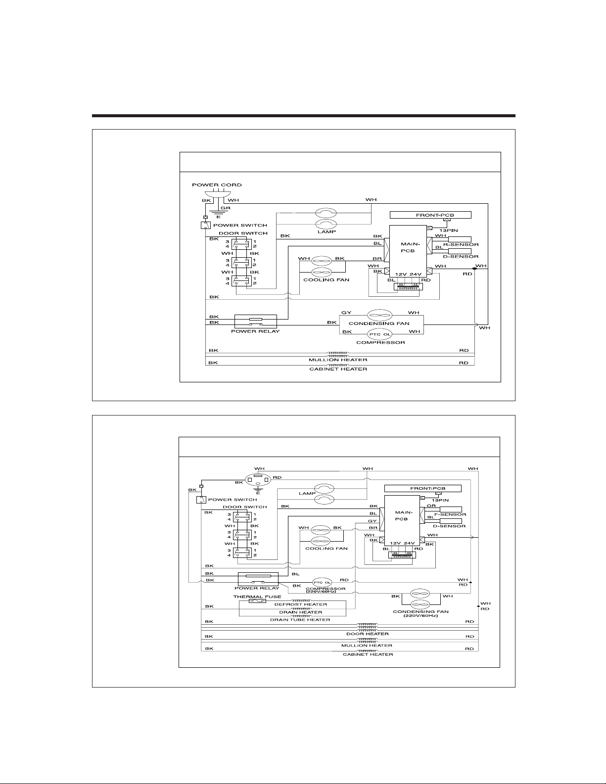
2-5. TSR-72SD
WIRING DIAGRAM
2-6. TSF-72SD
WIRING DIAGRAM
Page 8
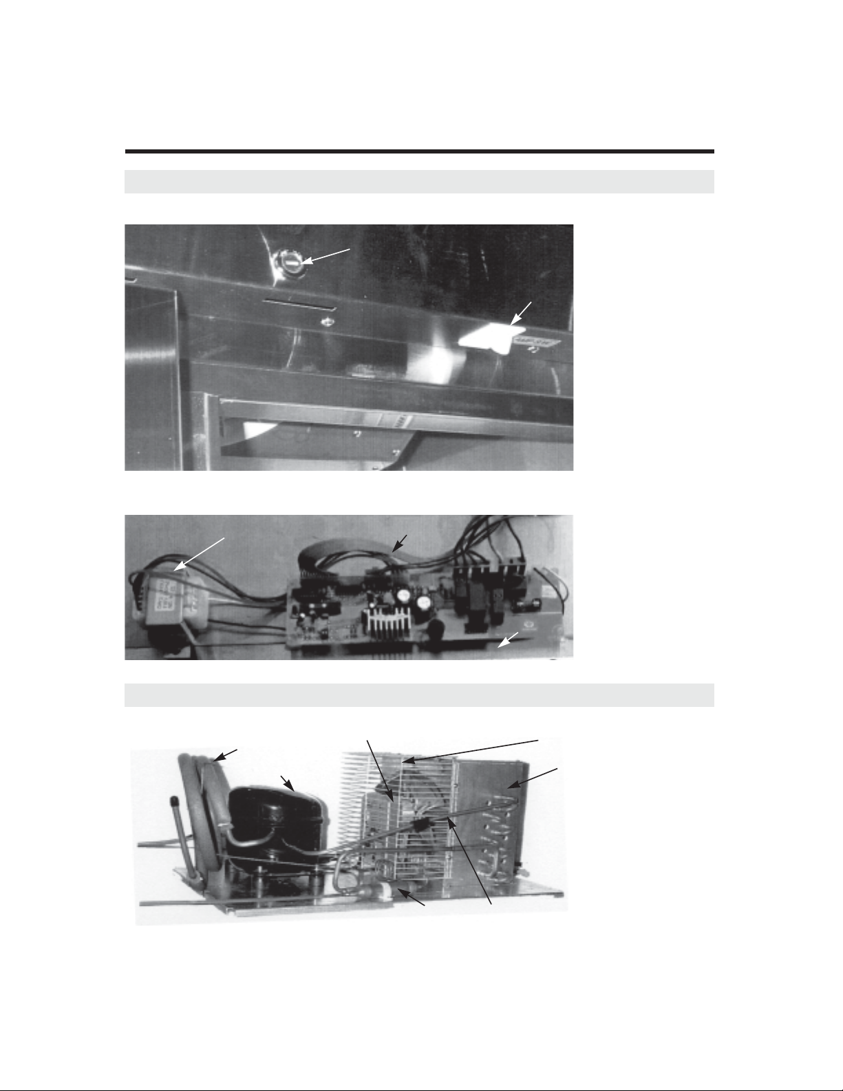
3. PART DETAILS
3-1. TOP GRILLE
Door Lock, Switch
Door Lock
Transformer, Main P.C.B
Door Switch
Transformer
3-2. Refrigeration Compartment
Cycle Assembly
Suction Pipe
Compressor
Condenser Fan Motor Assembly
Condenser Dryer
Harness
Main PCB
Condenser Coil Shroud
Condenser Coil
Condenser Pipe
Page 9
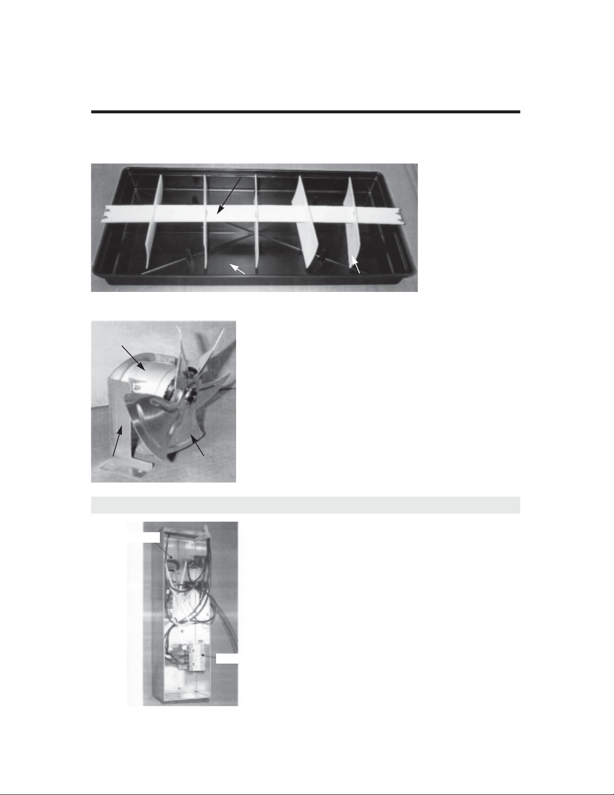
PART DETAILS
Drain Pan Assembly
Drain Wicking Bar
Drain Pan
Condenser Fan Motor Assembly
Condenser
Fan Motor
Bracket
Condenser Fan
Motor Blade
3-3. Electrical Box
Power Bushing
Drain Wicking Pads
Power Relay (Comp. Relay)
Page 10
PART DETA ILS
3-4. Door
Gasket
Gasket
3-5. Cooling Compartment
Freezer Duct & Refrigerator Duct (TSR-49SD, TSF-49SD, TSR-72SD, TSF-72SD Type)
Duct (A)
Freezer Evaporator, Fan (TSF-49SD, TSF-72SD)
Evaporator Fan Motor Blade
EvaporatorLamp Connector
Evaporator Thermal Fuse
Evaporator Fan
Motor Guard
Duct (B)
Heater Connectors &
Sensor Connectors
Page 11

PART DETAILS
Freezer Duct & Refrigerator Duct (TSR-23SD, TSF-23SD Type)
Evaporator Fan
Motor Guard
Duct (A)
Duct (B)
Freezer Evaporator, Fan (TSF-23SD)
Lamp & Fan Motor Connectors
Evaporator
Evaporator Coil Heater
Evaporator Fan
Motor Blade
Evaporator
Thermal
F-Sensor
Heater Connectors &
Sensor Connectors
Page 12
4. MAIN COMPONENTS
4-1. COMPRESSOR
Model TSR-23SD TSR-49SD TSF-23SD TSF-49SD TSR-72SD TSF-72SD
Comp. Model HBL27YE-1 SK6A1C-H2Y AEA2411ZXA AJA2425ZXA AKA4476YXA CAJ2446Z
Part code 3952127G10 3020014540 30200L0100 30200L0200 30200A4700 30206Q3600
Strating type CSR RSIR CSIR CSIR CSIR CSR
4-2. COMPRESSOR RELAY
Model TSR-23SD TSR-49SD TSF-23SD TSF-49SD TSR-72SD TSF-72SD
Relay Model 783RHBZZ-52 4TM811XHB-53 8300MRTL13 8300CRAN04 8300MRAM53 3ARR3-3A3A
4-3. CONDENSER DRYER
Model TSR-23SD TSR-49SD TSF-23SD TSF-49SD TSR-72SD TSF-72SD
)g05(9-HX.cepS
Part code 30268L0300 30268L0400 30268Q0100 30268Q0210
a404-Ra431-Ra404-Ra431-RtnaregirfeR
032/802zH06 / V511egatloV
zH06/V022zH06 / V511egatloV
a404-Ra431-Ra404-Ra431-RtnaregirfeR
4-4. CAPACITOR
Model TSR-23SD TSR-49SD TSF-23SD TSF-49SD TSR-72SD TSF-72SD
Running 230V/10uF x x 370V/15uF x 440V/15µF
ylbmessA.pmoC03151LE004edoc traP
Starting 200V/100uF x
165V/270~324uF 330V/161~193uF
ylbmessA.pmoC05053DR104edoc traP
378~445MFD 260V/88µF
zH06/V022zH06 / V511egatloV
Page 13
MAIN COMPONENTS
4-5. EVA FAN MOTOR
Model TSR-23SD TSR-49SD TSF-23SD TSF-49SD TSR-72SD TSF-72SD
zH06 / V511egatloV
A2-NSWD0244SIledoM rotoM
0218233693edoc traP
4-6. CONDENSOR FAN MOTOR
Model TSR-23SD TSR-49SD TSF-23SD TSF-49SD TSR-72SD TSF-72SD
4-7. EVA DEFROST HEATER
Model TSR-23SD TSR-49SD TSF-23SD TSF-49SD TSR-72SD TSF-72SD
zH06 / V511egatloV
W009xW006W544x.cepS
Part code x 30228L0802 30228L0700 x 30228Q0600
zH06/V022zH06 / V511egatloV
1-QSWD0244SI1-GSWD0244SIledoM rotoM
02022336930140223693edoc traP
4-8. LAMP BULB
Model TSR-23SD TSR-49SD TSF-23SD TSF-49SD TSR-72SD TSF-72SD
zH06 / V021egatloV
W52.cepS
0010L63203edoc traP
4-9. TRANSFORMER
Model TSR-23SD TSR-49SD TSF-23SD TSF-49SD TSR-72SD TSF-72SD
zH06 / V511egatloV
U511-SWD.cepS
0010L48203edoc traP
4-10. MAIN PCB
Model TSR-23SD TSR-49SD TSF-23SD TSF-49SD TSR-72SD TSF-72SD
zH06 / V511egatloV
Part code 30243L0310 30243L0200 30243L0300 30243L0310 30243Q0300
Micom code 1RF1151 1FF1153 2FF1153 1RF1151 3FF1151
* Last digit of micom code represents micom version.
Page 14
Page 15
Page 16
Page 17

Page 18

Page 19

Page 20

Page 21

Page 22

6. PART-LIST OF SOLID DOOR MODEL
Part name Code Material Description
Caster
Compressor
COMPRESSOR RUN CAPACITOR 400EL15130 230V/10µF
COMPRESSOR START CAPACITOR 401RD35050 200V/100µF
Z6442JAC0063Q60203ROSSERPMOC
COMPRESSOR POWER CORD (RELAY HARNESS)
COMPRESSOR POWER CORD (RELAY HARNESS)
COMPRESSOR POWER CORD (RELAY HARNESS)
COMPRESSOR POWER CORD (RELAY HARNESS)
COMPRESSOR POWER CORD (RELAY HARNESS)
POWER RELAY (COMP. RELAY) 8536490000
ELECTRICAL BOX HARNESS 30227L1711
ELECTRICAL BOX HARNESS 30227L0802
ELECTRICAL BOX HARNESS 30227Q1100
Condenser
CONDENSER COIL SHROUD 30214L4500
CONDENSER COIL SHROUD 30214L4600
CONDENSER COIL SHROUD 30214Q2800
30200L3400 INCLUDED PTC, OL
30227Q1400
30227L0502
30227L0602
30227L2800
G7L-1A-TUB(OMRON)
A51 ,V5210101A31203DROC REWOP NIAM
A03 ,V5111020Q31203DROC REWOP NIAM
1004L00203LIOC RESNEDNOC
1024L00203LIOC RESNEDNOC
1014L00203LIOC RESNEDNOC
2034L00203LIOC RESNEDNOC
0053Q00203LIOC RESNEDNOC
øDI 8733LT0221C0040Q44203EBUT YRALLIPAC
R-23S R-49S F-23S F-49S R-72S F-72S
222233
PDH-22-0405PT0020L56203RETSAC
222233
BLT-PDH-22-0405PT0010L56203EKARB RETSAC
1
1
1-EY72LBH01G7212593ROSSERPMOC
Y2H-C1A6KS0454100203ROSSERPMOC
AXZ1142AEA0010L00203ROSSERPMOC
AXZ5242AJA0020L00203ROSSERPMOC
AXY6744AKA0074A00203ROSSERPMOC
2.1øDI 059=LT0221C0030Q44203EBUT YRALLIPAC
2.1øDI 059LT0221C2031L44203EBUT YRALLIPAC
0.2øDI 5244LT0221C2041L44203EBUT YRALLIPAC
1
1
111111
1
11111
1
11
1
Model
1
1
1
1
1
1
11
1
1
1111
1
1
1
1
11
1
111
1
11
1
1
Page 23

PART-LIST OF SOLID DOOR MODEL
Part name Code Material Description
65.3øDI 3622LT0221C0001Q44203)A( EBUT YRALLIPAC
0.2øDI 5053LT0221C0011Q44203)B( EBUT YRALLIPAC
1.3ø g05 9-HXT0221C0030L86203REYRD RESNEDNOC
5.3ø g05 9-HXT0221C0040L86203REYRD RESNEDNOC
0.5ø g05 9-HXT0221C0010Q86203REYRD RESNEDNOC
0.5ø g05 9-HXT0221C0120Q86203REYRD RESNEDNOC
Condenser Fan
CONDENSER FAN MOTOR BLADE 30218B0100 AL ø225
CONDENSER FAN MOTOR BLADE 30218A0100 AL ø250
CONDENSER FAN MOTOR 3963220410 IS-4420DWSG-1
CONDENSER FAN MOTOR 3963322020 IS-4420DWSQ-1
Door
6-AP0001H7003GNIHSUB ROOD
0013L00203YLBMESSA ROOD
0092L00203YLBMESSA ROOD
DOOR ASSEMBLY(LEFT) 30200L2600
DOOR ASSEMBLY(LEFT) 30200L2400
DOOR ASSEMBLY(MIDDLE) 30200Q2320
DOOR ASSEMBLY(RIGHT) 30200L2700
DOOR ASSEMBLY(RIGHT) 30200L2500
DOOR ASSEMBLY(MIDDLE) 30200Q2330
S-CVP1120L32203TEKSAG ROOD
4.3ø0010L15203GNIRPS EGNIH ROOD
CABINET FRAME HEATER 30228L0111 45W
CABINET FRAME HEATER 30228L0203 60W
CABINET FRAME HEATER 30228Q0100 75W L=6700mm
034STS0052Q41203REVOC NOILLUM
mm0252=LW023090L82203RETAEH NOILLUM
mm0252=LW520030Q82203RETAEH NOILLUM
DOOR HINGE TOP ASSEMBLY LEFT 30229L0800 SPCC, T3.0 MFZN (WH)
DOOR HINGE TOP ASSEMBLY RIGHT 30229L0900 SPCC, T3.0 MFZN (WH)
DOOR HINGE BOTTOM ASSEMBLY LEFT 30229L0100 SPCC, T5.0 MFZN (WH)
DOOR HINGE BOTTOM ASSEMBLY RIGHT 30229L0200 SPCC, T5.0 MFZN (WH)
Drain
SPIH0070L11203NAP NIARD
R-23S R-49S F-23S F-49S R-72S F-72S
Model
11
1
11
11
1
1
11 2
111
11111
2
242433
1
1
11
11
1
11
11
1
121233
121233
11
11
11
1122
11
11
1111
111122
1111
111122
11
Page 24

PART-LIST OF SOLID DOOR MODEL
Part name Code Material Description
SPIH3010J11203NAP NIARD
H-CVP0070J03203RAB GNIKCIW NIARD
H-CVP0010L03203RAB GNIKCIW NIARD
5.2TPLUP0001L54203SDAP GNIKCIW NIARD
5.2TPLUP0070A54203SDAP GNIKCIW NIARD
Evaporator
6-AP0020L90203PAC NIARD
EVAPORATOR DRAIN PAN 30211L0501 A1100P-H14 0.8T, WH PAINTING
EVAPORATOR DRAIN PAN 30211L0601 A1100P-H14 0.8T, WH PAINTING
EVAPORATOR DRAIN PAN 30211Q0100 A1100P-H14 0.8T, WHPAINTING
0050L07203LIOC ROTAROPAVE
0060L07203LIOC ROTAROPAVE
1010L07203LIOC ROTAROPAVE
0020Q07203LIOC ROTAROPAVE
2020L07203LIOC ROTAROPAVE
0010Q07203LIOC ROTAROPAVE
0142L44203EPIP OMREHT
EVAPORATOR SENSOR 30227Q1200 F-Sensor, D-Sensor
EVAPORATOR SENSOR 30227Q1300 R-Sensor, D-Sensor
41H-P2505A2050L02203ERUTXIF NAP NIARD
EVAPORATOR THERMAL FUSE 30272L0400 250V/7.5A PST-3(80/10)
EVAPORATOR DRAIN ELBOW 30225L0100 PA-6
EVAPORATOR DEFROST HEATER 30228L0802 SUS304, ø8 445W
EVAPORATOR DEFROST HEATER 30228L0700 SUS304, ø8 600W
EVAPORATOR DEFROST HEATER 30228Q0600 SUS304, ø8 900W
EVAPORATOR DRAIN PAN HEATER 30228L1400 90W L=6,225mm
EVAPORATOR DRAIN PAN HEATER 30228Q0500 90W L=8,290m
EVAPORATOR DRAIN PAN HEATER 30228L1500 90W L=9,335mm
mm007=LW010131L82203RETAEH ESOH NIARD
DRAIN PAN INSULATOR 30233L0100 E-PS
DRAIN PAN INSULATOR 30233L0200 E-PS
DRAIN PAN INSULATOR 30233Q0100 E-PS
EVAPORATOR FAN MOTOR GUARD 30214K0100 ABS
EVAPORATOR FAN MOTOR BLADE 30218F0200 AL ø175
EVAPORATOR FAN MOTOR 3963328120 IS-4420DWSN-2A
R-23S R-49S F-23S F-49S R-72S F-72S
Model
1111
1111
11
55
5555
111111
11
11
11
1
1
1
1
1
1
11 1
11 1
11 1
111111
11 1
111111
1
1
1
1
1
1
11 1
11
11
11
121222
121222
121222
Page 25

PART-LIST OF SOLID DOOR MODEL
Part name Code Material Description
403 SUS4030L96203)A( TCUD
403 SUS4040L96203)A( TCUD
403 SUS0050Q96203)A( TCUD
403 SUS7050L96203)B( TCUD
403 SUS6060L96203)B( TCUD
403 SUS0040Q96203)B( TCUD
Top Grille Panel
TOP GRILLE PANEL ASSEMBLY 30224L0450
TOP GRILLE PANEL ASSEMBLY 30224L0230
TOP GRILLE PANEL ASSEMBLY 30224L0350
TOP GRILLE PANEL ASSEMBLY 30224L0130
TOP GRILLE PANEL ASSEMBLY 30200Q3800
TOP GRILLE PANEL ASSEMBLY 30200Q4000
LH-403STS4030L42203LENAP ELLIRG POT
LH-403STS4010L42203LENAP ELLIRG POT
LH-403STS0093Q00203LENAP ELLIRG POT
KCALBSBA0010Q61203 ELLIRG POT
KCALBSBA0020Q61203 ELLIRG POT
KCALBSBA0030Q61203 ELLIRG POT
0050Q24203OGOL DNARB
1001L72203SSENRAH BCP
0010G83203)YEK(KCOL ROOD
CONTROL BOARD HOUSING 30242L0100 BLACK, HOT-STAMP
0010Q34203BCP YALPSID
0010L34203BCP YALPSID
0030L34203BCP NIAM
0130L34203BCP NIAM
0020L34203BCP NIAM
0030Q34203BCP NIAM
POWER SWITCH (ROCKER SWITCH) 30281Q0100 125V/15A
Bottom Grille
BOTTOM GRILLE ASSEMBLY 30224L1410 STS304-HL
BLACK, HOT-STAMP
452.0T ,CP0090Q53203LEBAL TNORF
452.0T ,CP0010L53203LEBAL TNORF
D01-R102PS0010L18203HCTIWS ROOD
U511-SWD0010L48203REMROFSNART
R-23S R-49S F-23S F-49S R-72S F-72S
Model
11
11
11
11
11
11
1
1
1
1
1
1
11
11
11
11
11
11
111111
111111
11 1
11 1
121233
111111
11 1
1
1
11 1
1
1
111111
121233
111111
11
Page 26

PART-LIST OF SOLID DOOR MODEL
Part name Code Material Description
BOTTOM GRILLE ASSEMBLY 30224L1400 STS304-HL
BOTTOM GRILLE ASSEMBLY 30200Q4100 STS304-HL
Lamp
0090L72203SSENRAH PMAL
0010L97203TEKCOS PMAL
MEDIUM BASE
Shelf
6-AP0090L02203PILC FLEHS
403STS0010Q87203FLEHS
403STS0020Q87203FLEHS
403STS0120Q87203FLEHS
SHELF STANDARD (REAR POST ASSEMBLY)
SHELF STANDARD (FRONT POST ASSEMBLY)
COLD AIR FLOW GUIDE WIRE 30269Q0600 PE
30245Q0400 AL+STS L=51.5”
30245Q0410 AL+STS L=50”
YKLIMPP0023L41203DLEIHS PMAL
V021/W520010L63203BLUB PMAL
L-124B-PVC
”84=L ,T8.0B2-403STS1001L02203DRADNATS FLEHS
R-23S R-49S F-23S F-49S R-72S F-72S
Model
11
11
111122
111122
111122
111122
484844
12 24 12 24 36 36
33
669
9
22
22
6
Page 27

7. REPLACEMENT OF MAIN COMPONENTS
7-1. TOP GRILLE PARTS
- MAIN PCB or TRANSFORMER
- DISPLAY PCB
- DOOR LOCK or POWER SWITCH (ROCKER SWITCH)
- DOOR SWITCH
A. Unscrew the screw located both sides of top grille panel.
Page 28

REPLACEMENT OF MAIN COMPONENTS
B. Unscrew the screws located on top of top grille panel.
Page 29

REPLACEMENT OF MAIN COMPONENTS
C. Unscrew the screws located on bottom of top grille panel.
* Caution : When unscrewing, hold the top grille panel.
Falling down top grille may cause bruise.
D. Place the top grille panel on the top of the cabinet.
E. You can replace PCB, Transformer.
Page 30

REPLACEMENT OF MAIN COMPONENTS
F. Pull out the harness located back of top grille panel.
You can separate top grille panel.
You can replace power switch(rocker switch), door switches(lamp switch) and control board housing.
G. To re-assemble, do reversed in order.
Page 31

REPLACEMENT OF MAIN COMPONENTS
7-2. REPLACING DOOR
A. Disassemble top grille panel as described section 7-1 A.B.C.D.
B.
Remove Bottom Grille by unscrewing the four screws located on each side of the Bottom Grille.
C. Open the electrical box. Then uncap the door heater wire. (Freezer model only)
Page 32

D.
The figure of the disassembled top grille
panel.
REPLACEMENT OF MAIN COMPONENTS
E. Unscrew the hinge.
F. Unscrew the last screw with pushing the
hinge.
G. After unscrewing, the hinge will rotate
about 90˚(CCW), of itself.
Page 33

REPLACEMENT OF MAIN COMPONENTS
H. Lift the door and pull out the door heaterʼs lead wire.
I. Replace the door with the new one.
J. Ready the hinge as below. It is important to set initial position (angle).
Page 34

REPLACEMENT OF MAIN COMPONENTS
K. Initial position of the hinge must be as below.
L. Turn the hinge 90˚ CW. This turning causes torsion strength of the bar spring that
shuts the door(s) automatically.
M. Screw the hinge with pushing it. After installation of the door(s), assemble the top
grille panel.
Page 35

REPLACEMENT OF MAIN COMPONENTS
7-3. REFRIGERATION COMPARTMENTʼS PARTS
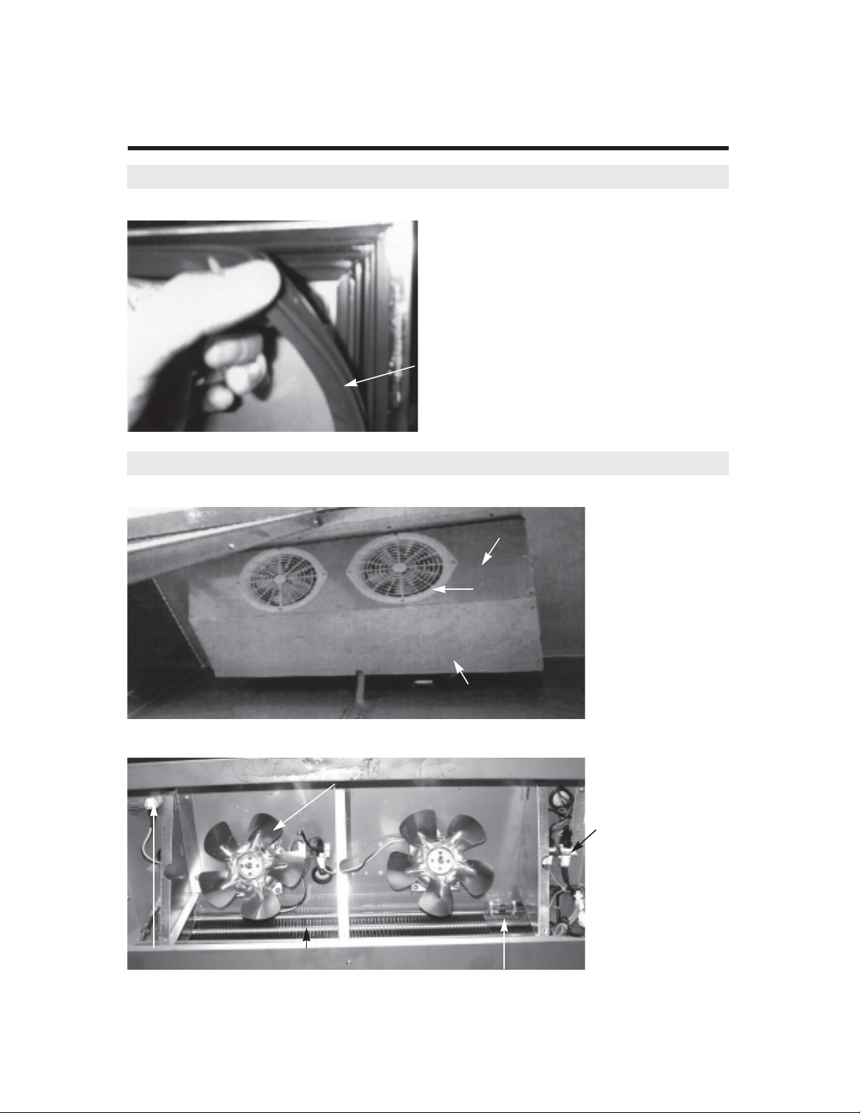
A. Disassemble lamp shield.
- LAMP BULB or LAMP SHIELD
- EVAPORATOR FAN MOTOR
- F/D SENSOR or R/D SENSOR
- EVAPORATOR DEFROST HEATER
- EVAPORATOR COIL
B. Disassemble Duct (A).
C. Pull out the lamp harness.
Page 36

REPLACEMENT OF MAIN COMPONENTS
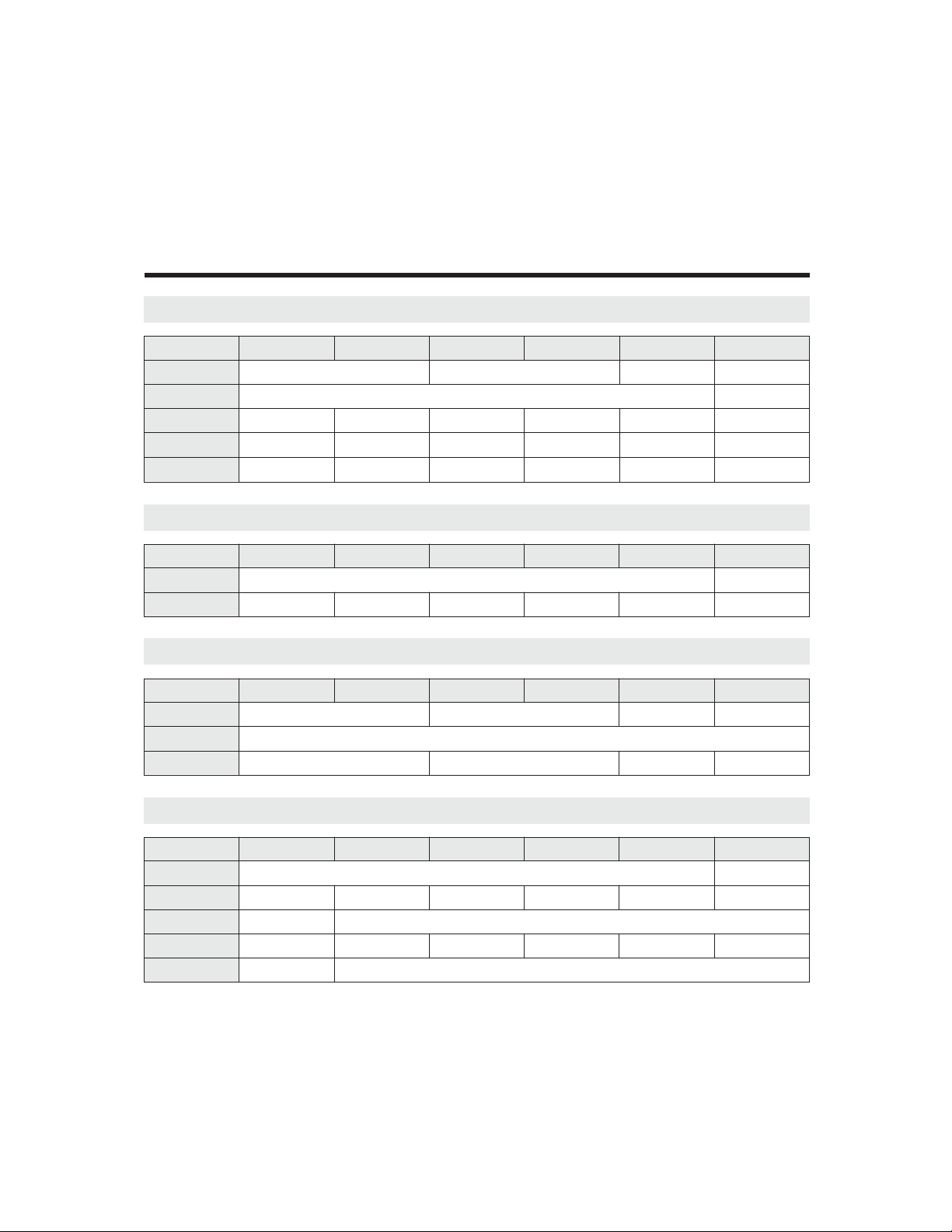
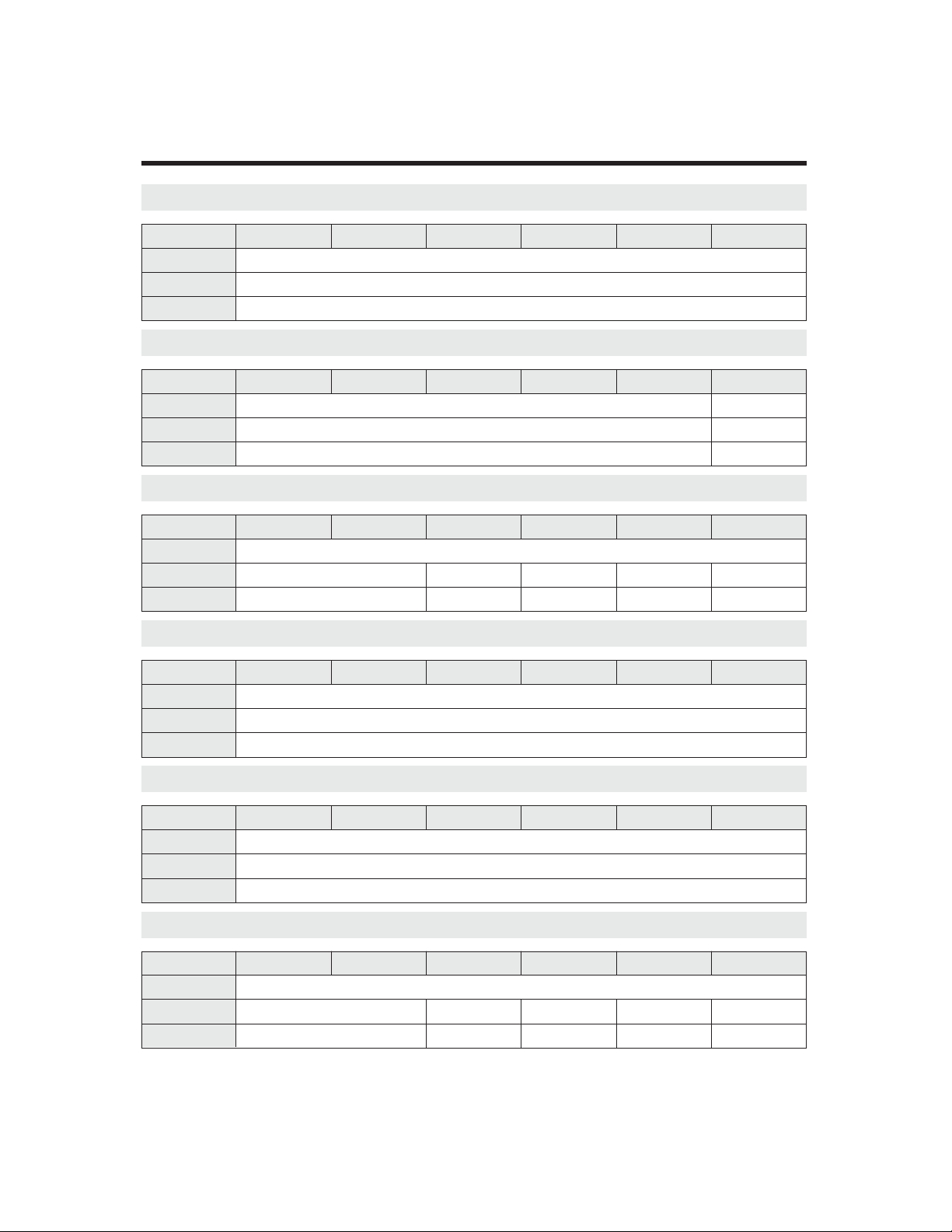
D. Disassembe duct (B).
E. Pull-out the evaporator drain pan heaterʼs leadwire.
F. Figure of disassembled refrigeration compartments.
In this situation, you can replace fan motor, F/D-sensor, Evaporator coil, ETC.
Page 37

REPLACEMENT OF MAIN COMPONENTS
G. Replacing evaporator fan motor
F-1. Pull out the fan motorʼs connector.
F-2. Unscrew the four screws which located on bottom of fan motor.
H. Replacing F/D-Sensor or R/D-Sensor
H-1. F-Sensor of Freezer
Unscrew as illustrated below and pull-out the F-Sensor from the cover.
F-Sensor
(Orange Color)
Page 38

H-2. D-Sensor of Freezer (Evaporator Defrost Sensor)
Disassemble the D-Sensor from evaporatorʼs end plate.
D-Sensor
(Blue Color)
REPLACEMENT OF MAIN COMPONENTS
H-3. R-Sensor of Refrigerator
Unscrew as illustrated below and pull-out the R-Sensor from the cover.
R-Sensor
(White Color)
Unscrew
TSR-49SD
TSR-72SD
R-Sensor
(White Color)
Unscrew
TSR-23SD
Page 39

REPLACEMENT OF MAIN COMPONENTS
H-4. D-Sensor of Refrigerator
Remove the absorber pad at the end of thermo-pipe and pull-out the D-Sensor.
D-Sensor
Thermo-Pipe
(Blue Color)
H-5. F/D Sensor or R/D Sensor
After unplug each sensor, pull-out the sensorʼs lead wire.
D-Sensor
F-Sensor
F/D Sensor
(F-Sensor : Orange Color,
D-Sensor : Blue Color)
D-Sensor
R-Sensor
R/D Sensor
(R-Sensor : White Color,
D-Sensor : Blue Color)
Page 40

REPLACEMENT OF MAIN COMPONENTS
REPLACING EVAPORATOR DEFROST HEATER (FREEZER ONLY)
A. After disassembling the duct(A) and the
duct(B), get ready as below for replacing
the evaporator defrost heater.
H. Split the hooks of the evaporator.
B. Pull out the pins from the bottom of the
evaporator using the nipper, etc.
Page 41

REPLACEMENT OF MAIN COMPONENTS
D. After removing all pins, disconnect the connectors from the thermal fuse and the main
E. Take apart the evaporator defrost heater from the evaporator.
Page 42

REPLACEMENT OF MAIN COMPONENTS
F. Install the new evaporator defrost heater in original position.
G. Pat the evaporator defrost heater with the soft hammer.
H. Pinch the hooks of the evaporator.
Page 43

REPLACEMENT OF MAIN COMPONENTS
I . Assemble the pins in original positions.
J. Connect the connectors of the evaporator defrost heater to them of the thermal fuse
* NOTE
Why is always 115 voltage detected between connectors of the evaporator defrost heater
in the main harness?
The SNUBBER(located Main PCB) holds two AC power lines simultaneously.
The SNUBBER prevents Main PCB malfunction from sparks occurred by other electrical
componentʼs ON/OFF. (SNUBBER = Spark killer)
Because of the SNUBBER, 115 voltage is always detected, but electrical current in this case is
very little(small Amps.). So, this electrical current is not enough to operate the evaporator
defrost heater.
How to measure the Amps. of the evaporator defrost heater.
Disconnect the connectors of the evaporator defrost heater.
Then, prepare the additional Power Source(115V/60Hz) and the Amp. Meter.
Connect the evaporator defrost heater to the additional power source and read amp. value from
the Amp. Meter.
Page 44

REPLACEMENT OF MAIN COMPONENTS
7-4. CONDENSING UNIT
- Condensing units : Compressor, Condenser Fan Motor, Condenser Coil, Condenser Dryer....
- Others : Compressor Power Cord (Relay harness), Main Power Cord, Electrical Box, ETC.
A. Disassemble Bottom Grille as described section 7-2. B.
B. Unscrew two screws as below.
C. Unplug the compressorʼs power plug.
Page 45

REPLACEMENT OF MAIN COMPONENTS
D. Pull-out the condensing unit.
Page 46

REPLACEMENT OF MAIN COMPONENTS
7-5. REPLACING CABINET FRAME HEATER (and/or) MULLION HEATER
A. Insert the and edge of ʻ–ʼtype screw
driver into the gap between the frame
and the frame cover.
C. Separate the frame cover by sliding the
screw driver.
B. Take apart the frame cover from the
frame.
D. Do just like above instructions in other
parts (bottom side, right side and top
side).
Page 47

REPLACEMENT OF MAIN COMPONENTS
E. Below picture shows the inlet of the
cabinet frame heater toward the
electrical box.
G. Pull out the heater wire from the inlet. H. Insert the new cabinet frame heater wire
F. Uncap connectors of the cabinet frame
heater.
to the inlet, after surrounding it along the
frame.
Page 48

REPLACEMENT OF MAIN COMPONENTS
I. Assemble the frame cover with the frame.
Push and slide the frame cover toward
corner.
K. Fit the other side of the frame cover, too. L. Pat the frame cover with the soft
J. Fit the end lines of the frame cover each
other.
hammer, etc.
Page 49

REPLACEMENT OF MAIN COMPONENTS
M. Do like above instructions in other parts (Left side, right side and top side).
Page 50

N. Unscrew the screws from the mullion.
REPLACEMENT OF MAIN COMPONENTS
O. Take apart the mullion cover from the
mullion.
P. Take care for the mullion heater not to
be hurt. (It does not matter, if this heater
is out of order).
Page 51

REPLACEMENT OF MAIN COMPONENTS
Q. Pull out the insulator from inside. R. Uncap connectors of the mullion heater.
S. Pull out the heater wire from the inlet.
Page 52

REPLACEMENT OF MAIN COMPONENTS
T. Pull out the mullion cover(SUS) from the mullion cover (ABS).
U. Change the old mullion heater and
install the new one with the gap between
wires 1.2 inch.
V. Insert the mullion cover(SUS) into the
original pisition.
Page 53

REPLACEMENT OF MAIN COMPONENTS
W. Connect the heater wires with the main harness and the electrical box harness.
X. Cover the caps on the connection parts and press them tightly.
 Loading...