

Page 1

Commercial
Refrigerator & Freezer
Service Manual
Solid Door
Model No.: TSR-23SD
TSR-49SD
TSR-72SD
TSF-23SD
TSF-49SD
TSF-72SD
Page 2

Commercial
Refrigerator & Freezer
Service Manual
Solid Door
Model No.: TSR-23SD
TSR-49SD
TSR-72SD
TSF-23SD
TSF-49SD
TSF-72SD
Page 3
1
TABLE OF CONTENTS
1. FEA TURE CHART
1-1. FRONT VIEW
1-2. SIDE VIEW
2. WIRING DIAGRAM
2-1. REFRIGERATOR (1DOOR) : TSR-23SD
2-2. FREEZER (1DOOR) : TSF-23SD
2-3. REFRIGERATOR (2DOOR) : TSR-49SD
2-4. FREEZER (2DOOR) : TSF-49SD
2-5. REFRIGERATOR (3DOOR) : TSR-72SD
2-6. FREEZER (3DOOR) : TSF-72SD
3. P ART DETAILS
3-1. TOP GRILLE
3-2. REFRIGERATION COMPARTMENT
3-3. ELECTRICAL BOX
3-4. DOOR
3-5. COOLING COMPARTMENT
4. MAIN COMPONENTS
4-1. COMPRESSOR
4-2. COMPRESSOR RELAY
4-3. CONDENSER DRYER
4-4. CAPACITOR
4-5. EVA FAN MOTOR
4-6. CONDENSOR FAN MOTOR
4-7. EVA DEFROST HEATER
4-8. LAMP
4-9. PCB TRANSFORMER
4-10. MAIN PCB
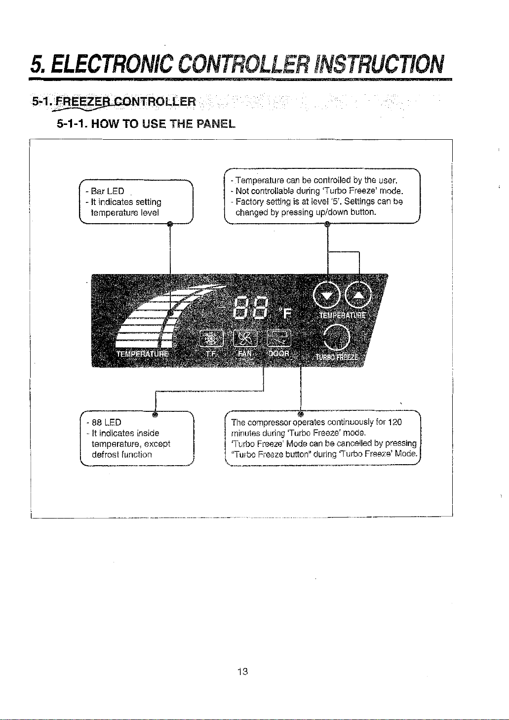
5. ELECTRONIC CONTROLLER INSTRUCTION
5-1. FREEZER CONTROLLER
5-1-1. HOW TO USE THE PANEL
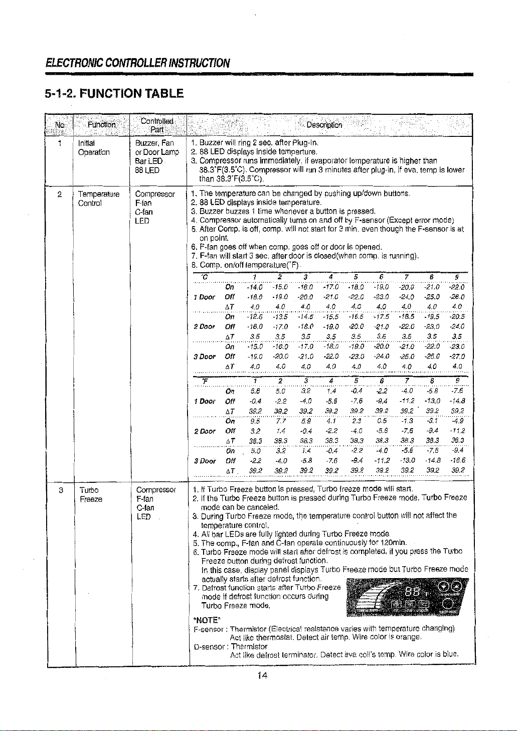
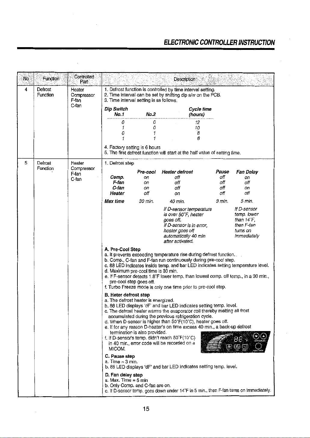
5-1-2. FUNCTION TABLE
5-1-3. ERROR CODE TABLE
5-2. REFRIGERATOR CONTROLLER
5-2-1. HOW TO USE THE PANEL
5-2-2. FUNCTION TABLE
5-2-3. ERROR CODE TABLE
6. SP ARE PARTS LIST
7. REPLACEMENT OF MAIN COMPONENTS
7-1. TOP GRILLE PARTS
7-2. REPLACING DOOR
7-3. REFRIGERATION COMPARTMENT’S PARTS
7-4. CONDENSING UNIT
7-5. REPLACING CABINET FRAME HEATER (AND/OR) MULLION HEATER
Page 4
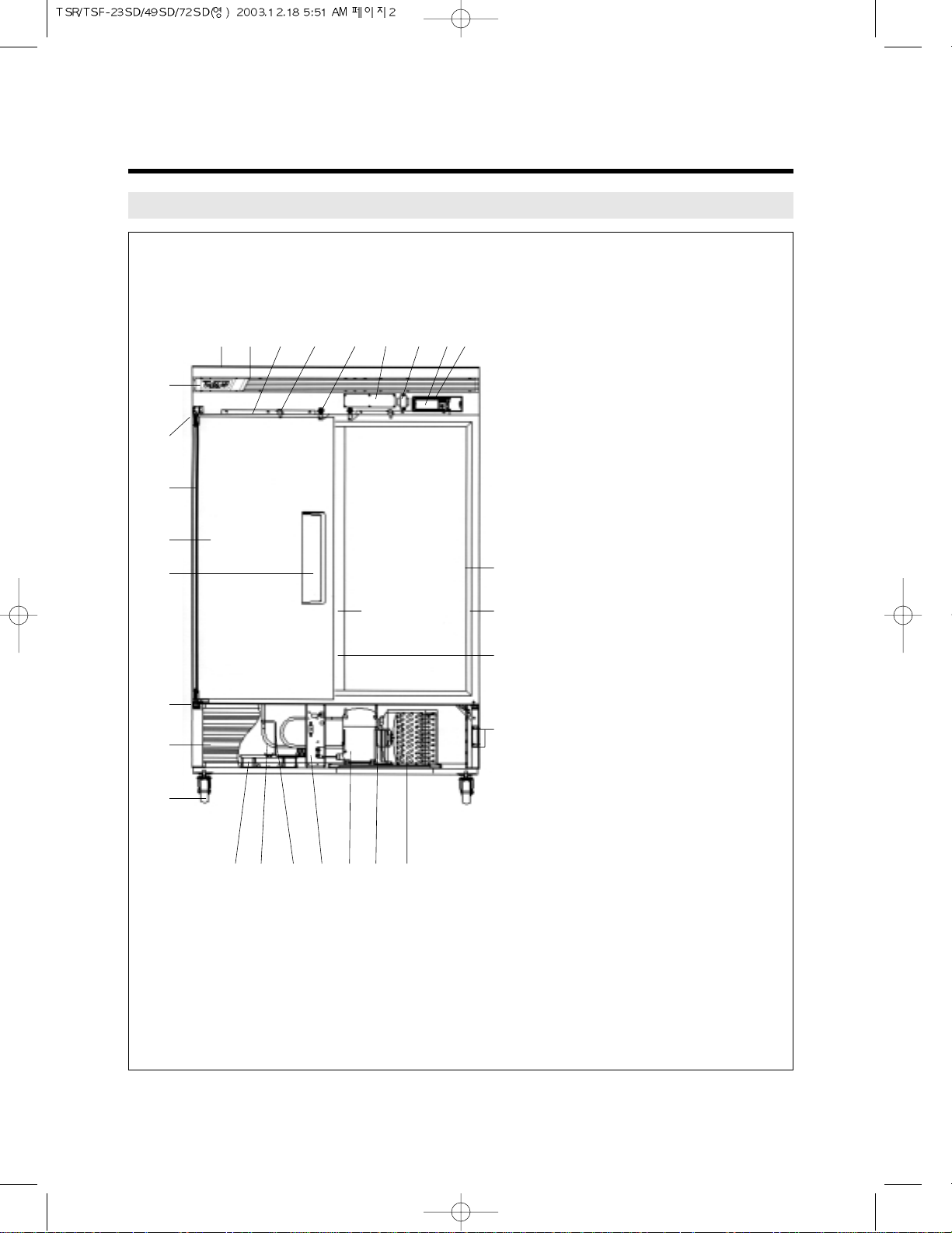
1-1. FRONT VIEW
2
1. FEATURE CHART
1 TOP GRILLE PANEL
2 TOP GRILLE
3 TOP GRILLE FIXTURE
4 DOOR SWITCH
5 DOOR LOCK
6 MAIN PCB
7 TRANSFORMER
8 DISPLAY PCB
9
CONTROL BOARD HOUSING
10 BRAND LOGO
11
DOOR HINGE TOP ASSEMBLY
12 DOOR HINGE SPRING
13 DOOR ASSEMBLY
14 DOOR HANDLE
15
DOOR HINGE BOTTOM ASSEMBLY
16
BOTTOM GRILLE ASSEMBLY
17 CASTER
18 DRAIN PAN
19 SUCTION PIPE
20 CAPILLARY TUBE
21 ELECTRICAL BOX
22 COMPRESSOR
23
CONDENSER FAN MOTOR
24 CONDENSER COIL
25 GRILLE FIXTURE
26
MULLION (CENTER POST)
27 MULLION HEATER
28 FRAME HEATER
29 FRAME COVER
1
0
q
k
l
h
g
w
e
r
t
y
u
iopasdf
23 4 56 789
j
Page 5
FEA TURE CHAR T
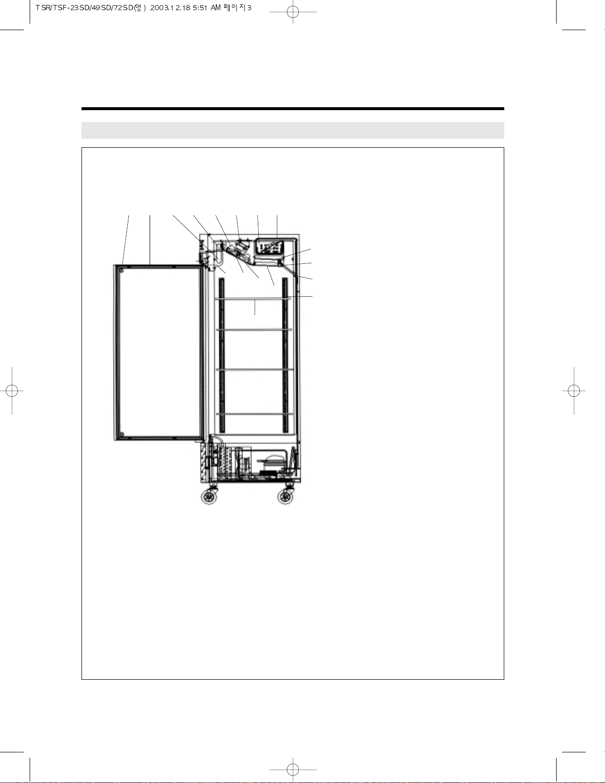
1-2. SIDE VIEW
3
l;zxcvbn
m
,
.
/
!
@
#
$
%
29 DOOR BUMPER
30 DOOR GASKET
31 LAMP BULB
32 LAMP SOCKET
33 EVAPORATOR FAN
MOTOR BLADE
34
EVAPORATOR FAN MOTOR
35 EVAPORATOR COIL
36 SUCTION PIPE
37
EVAPORATOR DRAIN PAN
38 EVAPORATOR DRAIN
ELBOW
39 DRAIN HOSE
40 SHELF STANDARD
41 LAMP SHIELD
42 EVAPORATOR FAN
MOTOR GUARD
43 DUCT (A) ‘FRONT’
44 DUCT (B) ‘BOTTOM’
45 SHELF
Page 6
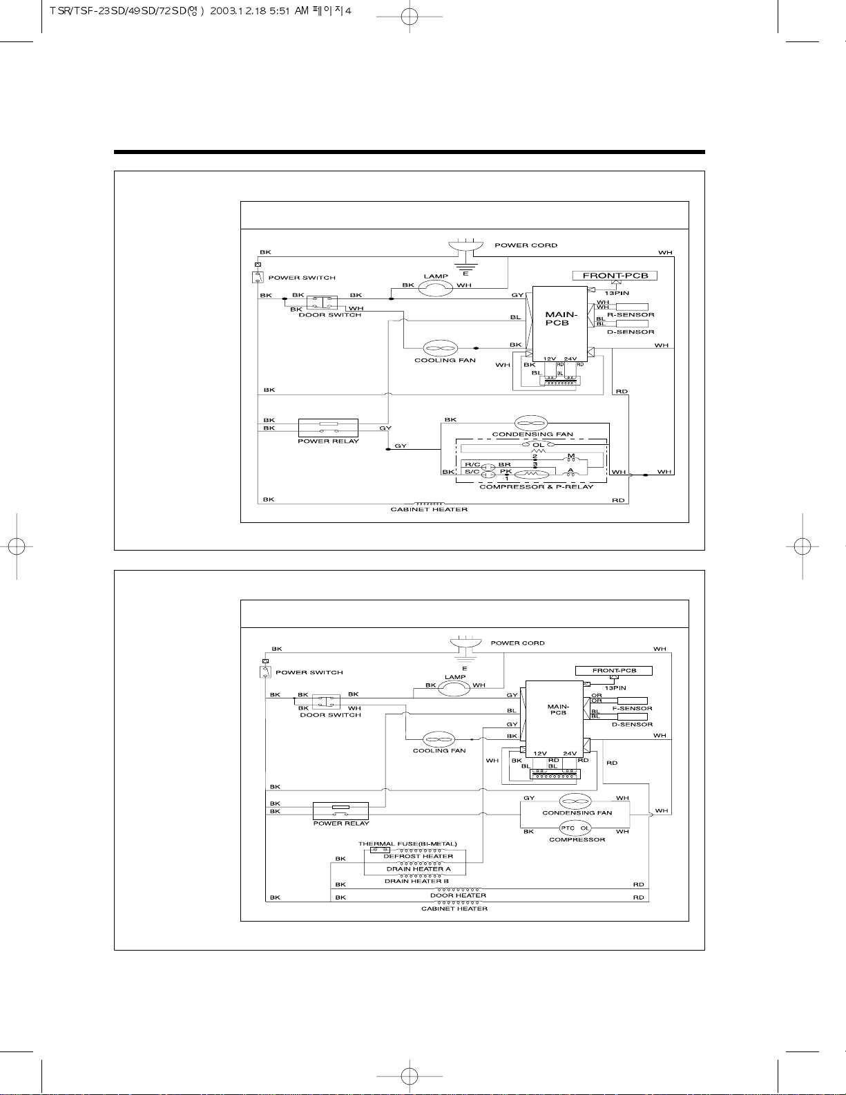
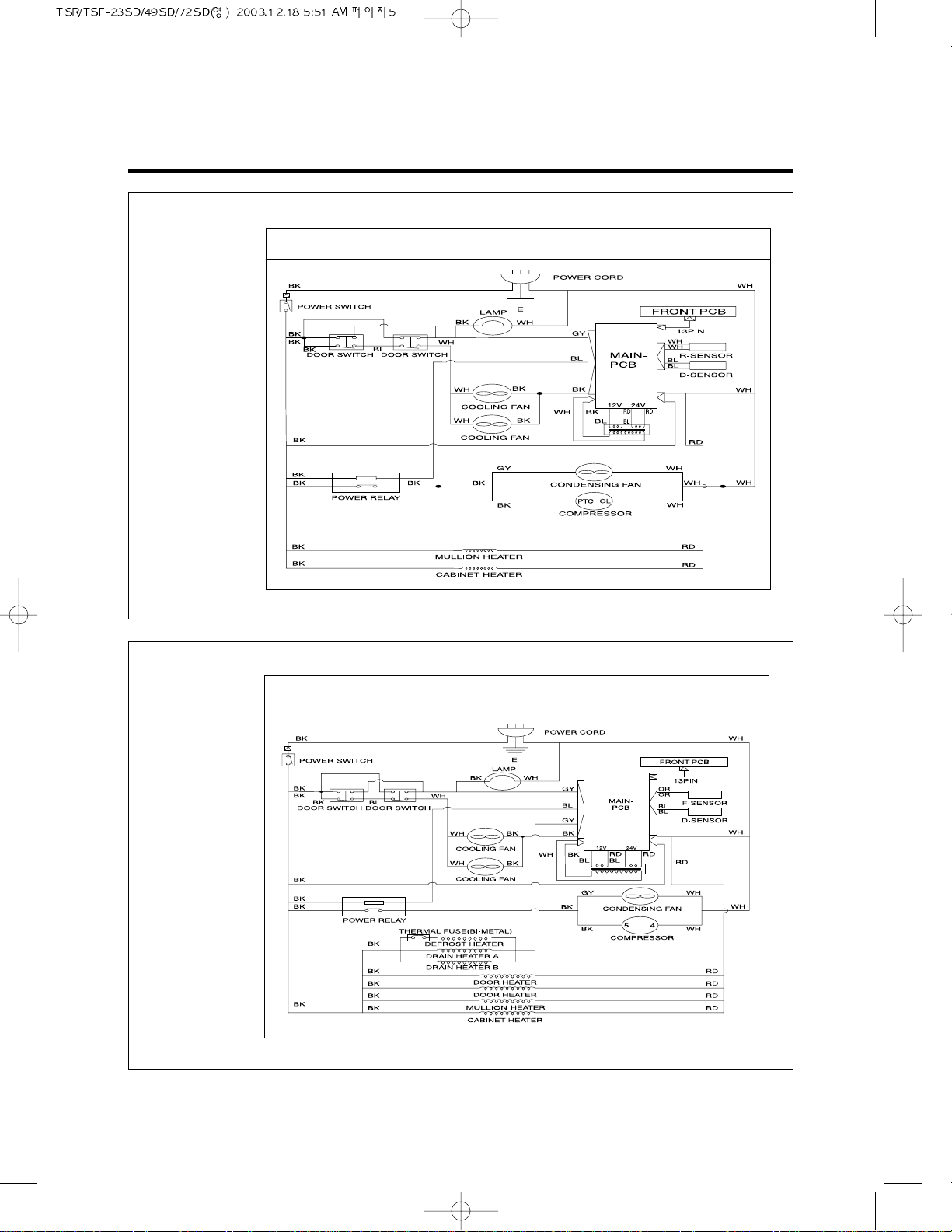
2. WIRING DIAGRAM
4
WIRING DIAGRAM
2-1. TSR-23SD
WIRING DIAGRAM
2-2. TSF-23SD
Page 7
5
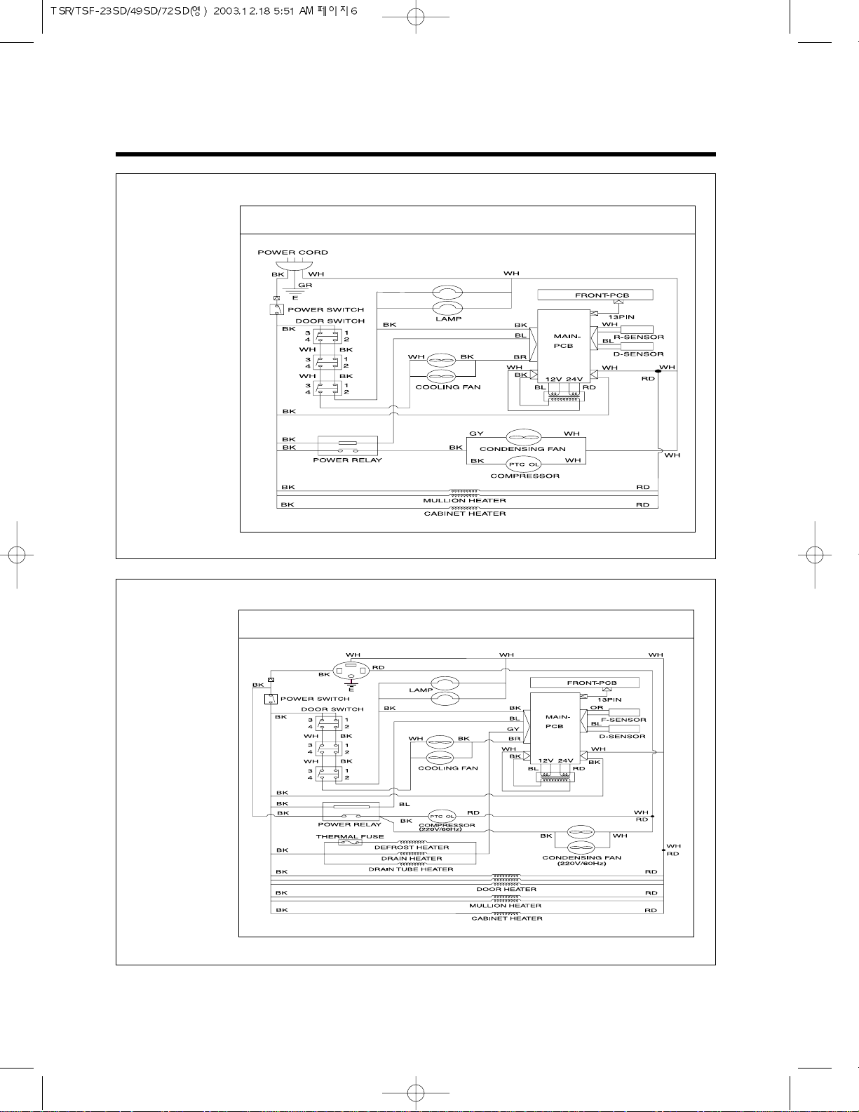
WIRING DIAGRAM
WIRING DIAGRAM
2-4. TSF-49SD
WIRING DIAGRAM
2-3. TSR-49SD
Page 8
6
WIRING DIAGRAM
WIRING DIAGRAM
2-6. TSF-72SD
WIRING DIAGRAM
2-5. TSR-72SD
Page 9
7
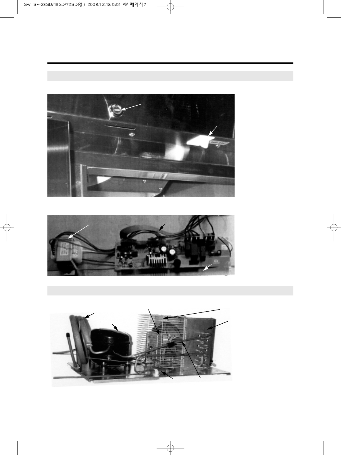
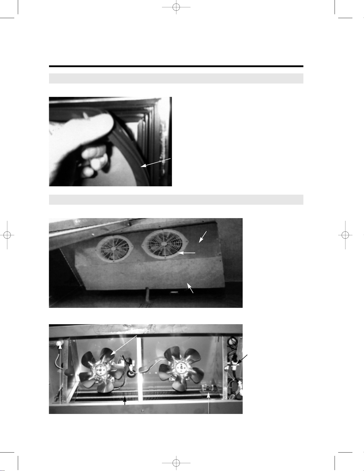
3. PART DETAILS
3-1. TOP GRILLE
Door Lock, Switch
3-2. Refrigeration Compartment
Cycle Assembly
Transformer, Main P.C.B
Transformer
Harness
Door Lock
Door Switch
Main PCB
Suction Pipe
Compressor
Condenser Fan Motor Assembly
Condenser Coil Shroud
Condenser Coil
Condenser Pipe
Condenser Dryer
Page 10
8
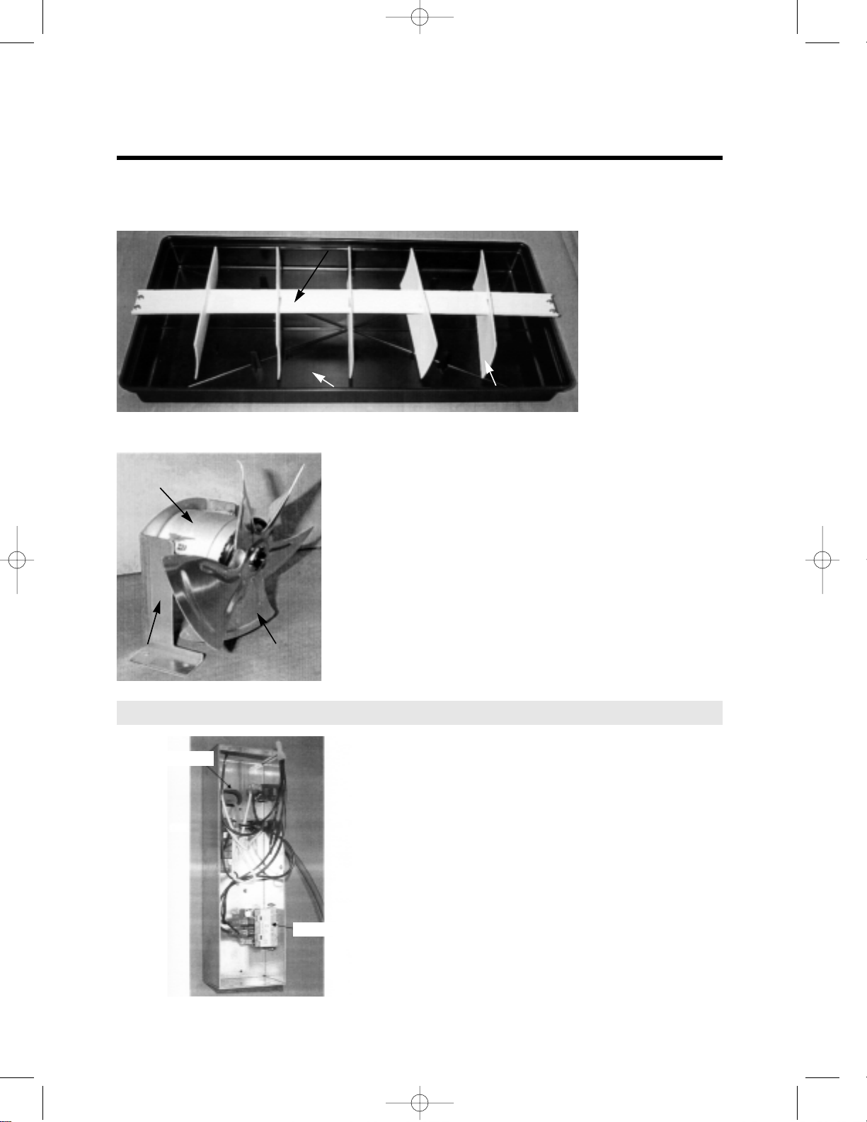
P AR T DETAILS
Drain Pan Assembly
Condenser Fan Motor Assembly
3-3. Electrical Box
Drain Wicking Bar
Drain Pan
Condenser
Fan Motor
Bracket
Condenser Fan
Motor Blade
Power Relay (Comp. Relay)
Power Bushing
Drain Wicking Pads
Page 11
9
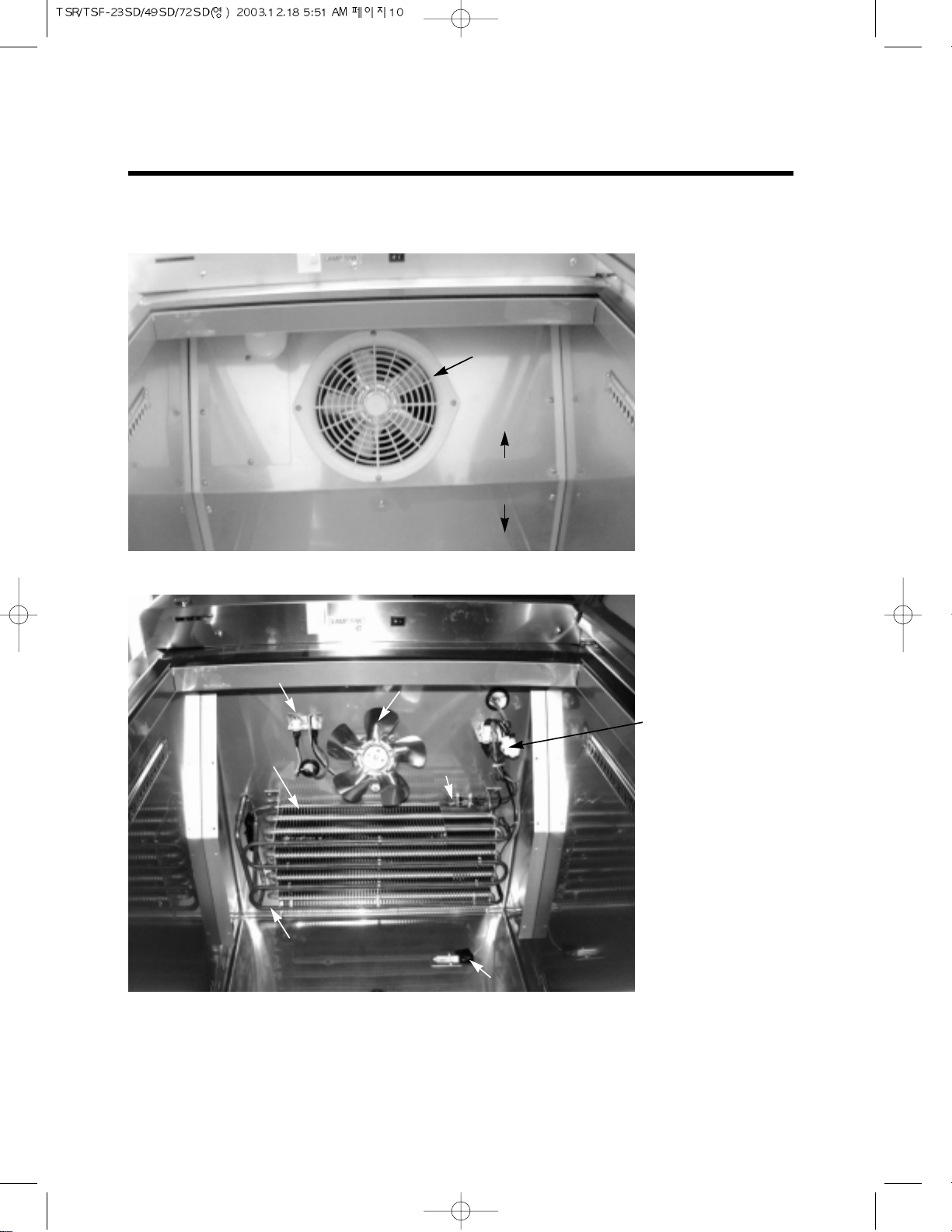
P AR T DETAILS
3-4. Door
Gasket
3-5. Cooling Compartment
Freezer Duct & Refrigerator Duct (TSR-49SD, TSF-49SD, TSR-72SD, TSF-72SD Type)
Freezer Evaporator, Fan (TSF-49SD, TSF-72SD)
Gasket
Evaporator Fan
Motor Guard
Duct (A)
Duct (B)
Evaporator Fan Motor Blade
Heater Connectors &
Sensor Connectors
Evaporator Thermal Fuse
EvaporatorLamp Connector
Page 12
10
P AR T DETAILS
Freezer Duct & Refrigerator Duct (TSR-23SD, TSF-23SD Type)
Freezer Evaporator, Fan (TSF-23SD)
Lamp & Fan Motor Connectors
Evaporator Fan
Motor Blade
Evaporator
Thermal
Evaporator
Evaporator Coil Heater
F-Sensor
Heater Connectors &
Sensor Connectors
Evaporator Fan
Motor Guard
Duct (A)
Duct (B)
Page 13
11
4. MAIN COMPONENTS
4-1. COMPRESSOR
Model TSR-23SD TSR-49SD TSF-23SD TSF-49SD TSR-72SD TSF-72SD
Refrigerant R-134a R-404a R-134a R-404a
Voltage 115V / 60Hz 208/230
Comp. Model HBL27YE-1 SK6A1C-H2Y AEA2411ZXA AJA2425ZXA AKA4476YXA CAJ2446Z
Part code 3952127G10 3020014540 30200L0100 30200L0200 30200A4700 30206Q3600
Strating type CSR RSIR CSIR CSIR CSIR CSR
4-4. CAPACITOR
Model TSR-23SD TSR-49SD TSF-23SD TSF-49SD TSR-72SD TSF-72SD
Voltage 115V / 60Hz 220V/60Hz
Running 230V/10uF x x 370V/15uF x 440V/15µF
Part code 400EL15130 Comp.Assembly
Starting 200V/100uF x
165V/270~324uF 330V/161~193uF
378~445MFD 260V/88µF
Part code 401RD35050 Comp.Assembly
4-3. CONDENSER DRYER
Model TSR-23SD TSR-49SD TSF-23SD TSF-49SD TSR-72SD TSF-72SD
Refrigerant R-134a R-404a R-134a R-404a
Spec. XH-9(50g)
Part code 30268L0300 30268L0400 30268Q0100 30268Q0210
4-2. COMPRESSOR RELAY
Model TSR-23SD TSR-49SD TSF-23SD TSF-49SD TSR-72SD TSF-72SD
Voltage 115V / 60Hz 220V/60Hz
Relay Model 783RHBZZ-52 4TM811XHB-53 8300MRTL13 8300CRAN04 8300MRAM53 3ARR3-3A3A
Page 14

12
MAIN COMPONENTS
4-5. EVA FAN MOTOR
Model TSR-23SD TSR-49SD TSF-23SD TSF-49SD TSR-72SD TSF-72SD
Voltage 115V / 60Hz
Motor Model IS4420DWSN-2A
Part code 3963328120
4-6. CONDENSOR FAN MOTOR
Model TSR-23SD TSR-49SD TSF-23SD TSF-49SD TSR-72SD TSF-72SD
Voltage 115V / 60Hz 220V/60Hz
Motor Model IS4420DWSG-1 IS4420DWSQ-1
Part code 3963220410 3963322020
4-8. LAMP BULB
Model TSR-23SD TSR-49SD TSF-23SD TSF-49SD TSR-72SD TSF-72SD
Voltage 120V / 60Hz
Spec. 25W
Part code 30236L0100
4-9. TRANSFORMER
Model TSR-23SD TSR-49SD TSF-23SD TSF-49SD TSR-72SD TSF-72SD
Voltage 115V / 60Hz
Spec. DWS-115U
Part code 30284L0100
4-10. MAIN PCB
Model TSR-23SD TSR-49SD TSF-23SD TSF-49SD TSR-72SD TSF-72SD
Voltage 115V / 60Hz
Part code 30243L0310 30243L0200 30243L0300 30243L0310 30243Q0300
Micom code 1RF1151 1FF1153 2FF1153 1RF1151 3FF1151
4-7. EVA DEFROST HEATER
Model TSR-23SD TSR-49SD TSF-23SD TSF-49SD TSR-72SD TSF-72SD
Voltage 115V / 60Hz
Spec. x 445W 600W x 900W
Part code x 30228L0802 30228L0700 x 30228Q0600
* Last digit of micom code represents micom version.
It may be changed without notice.
Page 15
Page 16
Page 17
Page 18

Page 19

Page 20

Page 21

Page 22

Page 23

21
6. PART-LIST OF SOLID DOOR MODEL
Caster
CASTER 30265L0200 TP5040-22-HDP
CASTER BRAKE 30265L0100 TP5040-22-HDP-TLB
Compressor
COMPRESSOR RUN CAPACITOR 400EL15130 230V/10µF
COMPRESSOR START CAPACITOR 401RD35050 200V/100µF
COMPRESSOR 3952127G10 HBL27YE-1
COMPRESSOR 3020014540 SK6A1C-H2Y
COMPRESSOR 30200L0100 AEA2411ZXA
COMPRESSOR 30200L0200 AJA2425ZXA
COMPRESSOR 30200A4700 AKA4476YXA
COMPRESSOR 30206Q3600 CAJ2446Z
COMPRESSOR POWER CORD (RELAY HARNESS)
30200L3400 INCLUDED PTC, OL
COMPRESSOR POWER CORD (RELAY HARNESS)
30227Q1400
COMPRESSOR POWER CORD (RELAY HARNESS)
30227L0502
COMPRESSOR POWER CORD (RELAY HARNESS)
30227L0602
COMPRESSOR POWER CORD (RELAY HARNESS)
30227L2800
POWER RELAY (COMP. RELAY) 8536490000
G7L-1A-TUB(OMRON)
ELECTRICAL BOX HARNESS 30227L1711
ELECTRICAL BOX HARNESS 30227L0802
ELECTRICAL BOX HARNESS 30227Q1100
MAIN POWER CORD 30213A1010 125V, 15A
MAIN POWER CORD 30213Q0201 115V, 30A
Condenser
CONDENSER COIL 30200L4001
CONDENSER COIL 30200L4201
CONDENSER COIL 30200L4101
CONDENSER COIL 30200L4302
CONDENSER COIL 30200Q3500
CONDENSER COIL SHROUD 30214L4500
CONDENSER COIL SHROUD 30214L4600
CONDENSER COIL SHROUD 30214Q2800
CAPILLARY TUBE 30244Q0300 C1220T L=950 IDø1.2
CAPILLARY TUBE 30244L1302 C1220T L950 IDø1.2
CAPILLARY TUBE 30244Q0400 C1220T L3378 IDø
CAPILLARY TUBE 30244L1402 C1220T L4425 IDø2.0
222233
222233
1
1
1
1
1
1
1
1
1
1
11
1
1
111111
1
1111
1
11111
1
1
1
1
11
1
11
111
1
1
11
1
1
Part name Code Material Description
Model
R-23S R-49S F-23S F-49S R-72S F-72S
Page 24

22
P AR T-LIST OF SOLID DOOR MODEL
CAPILLARY TUBE (A) 30244Q1000 C1220T L2263 IDø3.56
CAPILLARY TUBE (B) 30244Q1100 C1220T L3505 IDø2.0
CONDENSER DRYER 30268L0300 C1220T XH-9 50g ø3.1
CONDENSER DRYER 30268L0400 C1220T XH-9 50g ø3.5
CONDENSER DRYER 30268Q0100 C1220T XH-9 50g ø5.0
CONDENSER DRYER 30268Q0210 C1220T XH-9 50g ø5.0
Condenser Fan
CONDENSER FAN MOTOR BLADE 30218B0100 AL ø225
CONDENSER FAN MOTOR BLADE 30218A0100 AL ø250
CONDENSER FAN MOTOR 3963220410 IS-4420DWSG-1
CONDENSER FAN MOTOR 3963322020 IS-4420DWSQ-1
Door
DOOR BUSHING 3007H1000 PA-6
DOOR ASSEMBLY 30200L3100
DOOR ASSEMBLY 30200L2900
DOOR ASSEMBLY(LEFT) 30200L2600
DOOR ASSEMBLY(LEFT) 30200L2400
DOOR ASSEMBLY(MIDDLE) 30200Q2320
DOOR ASSEMBLY(RIGHT) 30200L2700
DOOR ASSEMBLY(RIGHT) 30200L2500
DOOR ASSEMBLY(MIDDLE) 30200Q2330
DOOR GASKET 30223L0211 PVC-S
DOOR HINGE SPRING 30251L0100 ø3.4
CABINET FRAME HEATER 30228L0111 45W
CABINET FRAME HEATER 30228L0203 60W
CABINET FRAME HEATER 30228Q0100 75W L=6700mm
MULLION COVER 30214Q2500 STS430
MULLION HEATER 30228L0903 20W L=2520mm
MULLION HEATER 30228Q0300 25W L=2520mm
DOOR HINGE TOP ASSEMBLY LEFT 30229L0800 SPCC, T3.0 MFZN (WH)
DOOR HINGE TOP ASSEMBLY RIGHT 30229L0900 SPCC, T3.0 MFZN (WH)
DOOR HINGE BOTTOM ASSEMBLY LEFT 30229L0100 SPCC, T5.0 MFZN (WH)
DOOR HINGE BOTTOM ASSEMBLY RIGHT 30229L0200 SPCC, T5.0 MFZN (WH)
Drain
DRAIN PAN 30211L0700 HIPS
11
1
11
11
1
1
11 2
111
11111
2
242433
1
1
11
11
1
11
11
1
121233
121233
11
11
11
1 122
11
11
1 111
111122
1 111
111122
11
Part name Code Material Description
Model
R-23S R-49S F-23S F-49S R-72S F-72S
Page 25

23
P AR T-LIST OF SOLID DOOR MODEL
DRAIN PAN 30211J0103 HIPS
DRAIN WICKING BAR 30230J0700 PVC-H
DRAIN WICKING BAR 30230L0100 PVC-H
DRAIN WICKING PADS 30245L1000 PULP T2.5
DRAIN WICKING PADS 30245A0700 PULP T2.5
Evaporator
DRAIN CAP 30209L0200 PA-6
EVAPORATOR DRAIN PAN 30211L0501 A1100P-H14 0.8T, WH PAINTING
EVAPORATOR DRAIN PAN 30211L0601 A1100P-H14 0.8T, WH PAINTING
EVAPORATOR DRAIN PAN 30211Q0100 A1100P-H14 0.8T, WHPAINTING
EVAPORATOR COIL 30270L0500
EVAPORATOR COIL 30270L0600
EVAPORATOR COIL 30270L0101
EVAPORATOR COIL 30270Q0200
EVAPORATOR COIL 30270L0202
EVAPORATOR COIL 30270Q0100
THERMO PIPE 30244L2410
EVAPORATOR SENSOR 30227Q1200 F-Sensor, D-Sensor
EVAPORATOR SENSOR 30227Q1300 R-Sensor, D-Sensor
DRAIN PAN FIXTURE 30220L0502 A5052P-H14
EVAPORATOR THERMAL FUSE 30272L0400 250V/7.5A PST-3(80/10)
EVAPORATOR DRAIN ELBOW 30225L0100 PA-6
EVAPORATOR DEFROST HEATER 30228L0802 SUS304, ø8 445W
EVAPORATOR DEFROST HEATER 30228L0700 SUS304, ø8 600W
EVAPORATOR DEFROST HEATER 30228Q0600 SUS304, ø8 900W
EVAPORATOR DRAIN PAN HEATER 30228L1400 90W L=6,225mm
EVAPORATOR DRAIN PAN HEATER 30228Q0500 90W L=8,290m
EVAPORATOR DRAIN PAN HEATER 30228L1500 90W L=9,335mm
DRAIN HOSE HEATER 30228L1310 10W L=700mm
DRAIN PAN INSULATOR 30233L0100 E-PS
DRAIN PAN INSULATOR 30233L0200 E-PS
DRAIN PAN INSULATOR 30233Q0100 E-PS
EVAPORATOR FAN MOTOR GUARD 30214K0100 ABS
EVAPORATOR FAN MOTOR BLADE 30218F0200 AL ø175
EVAPORATOR FAN MOTOR 3963328120 IS-4420DWSN-2A
1 111
1 111
11
55
5 555
111111
11
11
11
1
1
1
1
1
1
11 1
11 1
11 1
111111
11 1
111111
1
1
1
1
1
1
11 1
11
11
11
121222
121222
121222
Part name Code Material Description
Model
R-23S R-49S F-23S F-49S R-72S F-72S
Page 26

24
P AR T-LIST OF SOLID DOOR MODEL
DUCT (A) 30269L0304 SUS 304
DUCT (A) 30269L0404 SUS 304
DUCT (A) 30269Q0500 SUS 304
DUCT (B) 30269L0507 SUS 304
DUCT (B) 30269L0606 SUS 304
DUCT (B) 30269Q0400 SUS 304
Top Grille Panel
TOP GRILLE PANEL ASSEMBLY 30224L0450
TOP GRILLE PANEL ASSEMBLY 30224L0230
TOP GRILLE PANEL ASSEMBLY 30224L0350
TOP GRILLE PANEL ASSEMBLY 30224L0130
TOP GRILLE PANEL ASSEMBLY 30200Q3800
TOP GRILLE PANEL ASSEMBLY 30200Q4000
TOP GRILLE PANEL 30224L0304 STS304-HL
TOP GRILLE PANEL 30224L0104 STS304-HL
TOP GRILLE PANEL 30200Q3900 STS304-HL
TOP GRILLE 30216Q0100 ABS BLACK
TOP GRILLE 30216Q0200 ABS BLACK
TOP GRILLE 30216Q0300 ABS BLACK
BRAND LOGO 30242Q0500
BLACK, HOT-STAMP
PCB HARNESS 30227L1001
FRONT LABEL 30235Q0900 PC, T0.254
FRONT LABEL 30235L0100 PC, T0.254
DOOR LOCK(KEY) 30238G0100
CONTROL BOARD HOUSING 30242L0100 BLACK, HOT-STAMP
DISPLAY PCB 30243Q0100
DISPLAY PCB 30243L0100
MAIN PCB 30243L0300
MAIN PCB 30243L0310
MAIN PCB 30243L0200
MAIN PCB 30243Q0300
POWER SWITCH (ROCKER SWITCH) 30281Q0100 125V/15A
DOOR SWITCH 30281L0100 SP201R-10D
TRANSFORMER 30284L0100 DWS-115U
Bottom Grille
BOTTOM GRILLE ASSEMBLY 30224L1410 STS304-HL
R-23S R-49S F-23S F-49S R-72S F-72S
11
11
11
11
11
11
1
1
1
1
1
1
11
11
11
11
11
11
111111
111111
11 1
11 1
121233
111111
11 1
1
1
11 1
1
1
111111
121233
111111
11
Part name Code Material Description
Model
Page 27

P AR T-LIST OF SOLID DOOR MODEL
BOTTOM GRILLE ASSEMBLY 30224L1400 STS304-HL
BOTTOM GRILLE ASSEMBLY 30200Q4100 STS304-HL
Lamp
LAMP SHIELD 30214L3200 PP MILKY
LAMP HARNESS 30227L0900
LAMP BULB 30236L0100 25W/120V
LAMP SOCKET 30279L0100
MEDIUM BASE
L-124B-PVC
Shelf
SHELF STANDARD 30220L1001 STS304-2B 0.8T, L=48”
SHELF CLIP 30220L0900 PA-6
SHELF 30278Q0100 STS304
SHELF 30278Q0200 STS304
SHELF 30278Q0210 STS304
SHELF STANDARD (REAR POST ASSEMBLY)
30245Q0400 AL+STS L=51.5”
SHELF STANDARD (FRONT POST ASSEMBLY)
30245Q0410 AL+STS L=50”
COLD AIR FLOW GUIDE WIRE 30269Q0600 PE
25
11
11
111122
111122
111122
111122
484844
12 24 12 24 36 36
33
669
9
22
22
6
Part name Code Material Description
Model
R-23S R-49S F-23S F-49S R-72S F-72S
Page 28

26
7. REPLACEMENT OF MAIN COMPONENTS
7-1. TOP GRILLE PARTS
- MAIN PCB or TRANSFORMER
- DISPLAY PCB
- DOOR LOCK or POWER SWITCH (ROCKER SWITCH)
- DOOR SWITCH
A. Unscrew the screw located both sides of top grille panel.
Page 29

27
REPLACEMENT OF MAIN COMPONENTS
B. Unscrew the screws located on top of top grille panel.
Page 30

28
REPLACEMENT OF MAIN COMPONENTS
C. Unscrew the screws located on bottom of top grille panel.
* Caution : When unscrewing, hold the top grille panel.
Falling down top grille may cause bruise.
D. Place the top grille panel on the top of the cabinet.
E. You can replace PCB, Transformer.
Page 31

29
REPLACEMENT OF MAIN COMPONENTS
F. Pull out the harness located back of top grille panel.
You can separate top grille panel.
You can replace power switch(rocker switch), door switches(lamp switch) and control board housing.
G. To re-assemble, do reversed in order.
Page 32

30
REPLACEMENT OF MAIN COMPONENTS
7-2. REPLACING DOOR
A. Disassemble top grille panel as described section 7-1 A.B.C.D.
B.
Remove Bottom Grille by unscrewing the four screws located on each side of the Bottom Grille.
C. Open the electrical box. Then uncap the door heater wire. (Freezer model only)
Page 33

31
REPLACEMENT OF MAIN COMPONENTS
D.
The figure of the disassembled top grille
panel.
E. Unscrew the hinge.
F. Unscrew the last screw with pushing the
hinge.
G. After unscrewing, the hinge will rotate
about 90˚(CCW), of itself.
Page 34

32
REPLACEMENT OF MAIN COMPONENTS
H. Lift the door and pull out the door heater’s lead wire.
I. Replace the door with the new one.
J. Ready the hinge as below. It is important to set initial position (angle).
Page 35

33
REPLACEMENT OF MAIN COMPONENTS
K. Initial position of the hinge must be as below.
L. Turn the hinge 90˚ CW. This turning causes torsion strength of the bar spring that
shuts the door(s) automatically.
M. Screw the hinge with pushing it. After installation of the door(s), assemble the top
grille panel.
Page 36

34
REPLACEMENT OF MAIN COMPONENTS
7-3. REFRIGERATION COMPARTMENT’S PARTS
A. Disassemble lamp shield.
- LAMP BULB or LAMP SHIELD
- EVAPORATOR FAN MOTOR
- F/D SENSOR or R/D SENSOR
- EVAPORATOR DEFROST HEATER
- EVAPORATOR COIL
B. Disassemble Duct (A).
C. Pull out the lamp harness.
Page 37

35
REPLACEMENT OF MAIN COMPONENTS
D. Disassembe duct (B).
E. Pull-out the evaporator drain pan heater’s leadwire.
F. Figure of disassembled refrigeration compartments.
In this situation, you can replace fan motor, F/D-sensor, Evaporator coil, ETC.
Page 38

36
G. Replacing evaporator fan motor
F-1. Pull out the fan motor’s connector.
F-2. Unscrew the four screws which located on bottom of fan motor.
H. Replacing F/D-Sensor or R/D-Sensor
H-1. F-Sensor of Freezer
Unscrew as illustrated below and pull-out the F-Sensor from the cover.
F-Sensor
(Orange Color)
REPLACEMENT OF MAIN COMPONENTS37REPLACEMENT OF MAIN COMPONENTS
Page 39

H-3. R-Sensor of Refrigerator
Unscrew as illustrated below and pull-out the R-Sensor from the cover.
TSR-49SD
TSR-72SD
TSR-23SD
H-2. D-Sensor of Freezer (Evaporator Defrost Sensor)
Disassemble the D-Sensor from evaporator’s end plate.
D-Sensor
(Blue Color)
R-Sensor
(White Color)
R-Sensor
(White Color)
Unscrew
Unscrew
Page 40

38
H-5. F/D Sensor or R/D Sensor
After unplug each sensor, pull-out the sensor’s lead wire.
H-4. D-Sensor of Refrigerator
Remove the absorber pad at the end of thermo-pipe and pull-out the D-Sensor.
D-Sensor
(Blue Color)
Thermo-Pipe
D-Sensor
D-Sensor
R-Sensor
F-Sensor
F/D Sensor
(F-Sensor : Orange Color,
D-Sensor : Blue Color)
R/D Sensor
(R-Sensor : White Color,
D-Sensor : Blue Color)
REPLACEMENT OF MAIN COMPONENTS39REPLACEMENT OF MAIN COMPONENTS
Page 41

A. After disassembling the duct(A) and the
duct(B), get ready as below for replacing
the evaporator defrost heater.
B. Pull out the pins from the bottom of the
evaporator using the nipper, etc.
H. Split the hooks of the evaporator.
REPLACING EVAPORATOR DEFROST HEATER (FREEZER ONLY)
Page 42

40
REPLACEMENT OF MAIN COMPONENTS
D. After removing all pins, disconnect the connectors from the thermal fuse and the main
E. Take apart the evaporator defrost heater from the evaporator.
Page 43

41
REPLACEMENT OF MAIN COMPONENTS
F. Install the new evaporator defrost heater in original position.
G. Pat the evaporator defrost heater with the soft hammer.
H. Pinch the hooks of the evaporator.
Page 44

42
REPLACEMENT OF MAIN COMPONENTS
I . Assemble the pins in original positions.
J. Connect the connectors of the evaporator defrost heater to them of the thermal fuse
* NOTE
Why is always 115 voltage detected between connectors of the evaporator defrost heater
in the main harness?
The SNUBBER(located Main PCB) holds two AC power lines simultaneously.
The SNUBBER prevents Main PCB malfunction from sparks occurred by other electrical
component’s ON/OFF. (SNUBBER = Spark killer)
Because of the SNUBBER, 115 voltage is always detected, but electrical current in this case is
very little(small Amps.). So, this electrical current is not enough to operate the evaporator
defrost heater.
How to measure the Amps. of the evaporator defrost heater.
Disconnect the connectors of the evaporator defrost heater.
Then, prepare the additional Power Source(115V/60Hz) and the Amp. Meter.
Connect the evaporator defrost heater to the additional power source and read amp. value from
the Amp. Meter.
Page 45

43
REPLACEMENT OF MAIN COMPONENTS
7-4. CONDENSING UNIT
- Condensing units : Compressor, Condenser Fan Motor, Condenser Coil, Condenser Dryer....
- Others : Compressor Power Cord (Relay harness), Main Power Cord, Electrical Box, ETC.
A. Disassemble Bottom Grille as described section 7-2. B.
B. Unscrew two screws as below.
C. Unplug the compressor’s power plug.
Page 46

44
D. Pull-out the condensing unit.
REPLACEMENT OF MAIN COMPONENTS45REPLACEMENT OF MAIN COMPONENTS
Page 47

7-5. REPLACING CABINET FRAME HEATER (and/or) MULLION HEATER
A. Insert the and edge of ‘–’type screw
driver into the gap between the frame
and the frame cover.
B. Take apart the frame cover from the
frame.
C. Separate the frame cover by sliding the
screw driver.
D. Do just like above instructions in other
parts (bottom side, right side and top
side).
Page 48

46
REPLACEMENT OF MAIN COMPONENTS
E. Below picture shows the inlet of the
cabinet frame heater toward the
electrical box.
F. Uncap connectors of the cabinet frame
heater.
G. Pull out the heater wire from the inlet. H. Insert the new cabinet frame heater wire
to the inlet, after surrounding it along the
frame.
Page 49

47
REPLACEMENT OF MAIN COMPONENTS
I. Assemble the frame cover with the frame.
Push and slide the frame cover toward
corner.
J. Fit the end lines of the frame cover each
other.
K. Fit the other side of the frame cover, too. L. Pat the frame cover with the soft
hammer, etc.
Page 50

48
REPLACEMENT OF MAIN COMPONENTS
M. Do like above instructions in other parts (Left side, right side and top side).
Page 51

49
REPLACEMENT OF MAIN COMPONENTS
N. Unscrew the screws from the mullion.
O. Take apart the mullion cover from the
mullion.
P. Take care for the mullion heater not to
be hurt. (It does not matter, if this heater
is out of order).
Page 52

50
REPLACEMENT OF MAIN COMPONENTS
S. Pull out the heater wire from the inlet.
Q. Pull out the insulator from inside. R. Uncap connectors of the mullion heater.
Page 53

51
REPLACEMENT OF MAIN COMPONENTS
U. Change the old mullion heater and
install the new one with the gap between
wires 1.2 inch.
V. Insert the mullion cover(SUS) into the
original pisition.
T. Pull out the mullion cover(SUS) from the mullion cover (ABS).
Page 54

52
REPLACEMENT OF MAIN COMPONENTS
W. Connect the heater wires with the main harness and the electrical box harness.
X. Cover the caps on the connection parts and press them tightly.
 Loading...