

Page 1
A
SERVICE M
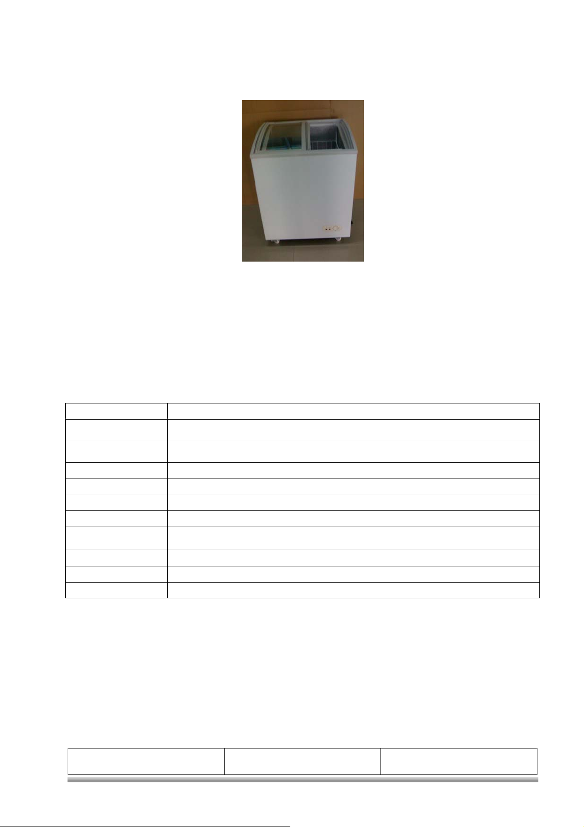
CHEST FREEZER
Model : TSD-27CF
NUAL
TSD-27CF
Specification: Subject to change without notice.
SPECIFICATION TSD-27CF
Classification Direct Cool, Manual Defrost, Tropical
Power Source 115VAC, 60 Hz.
Volume 138 Liters (4.9 cu.ft)
Rated Current 2.0 Amp.
Rated Power Input 135 Watts
Power Consumption
High side /Low side
pressure
1.30 kW·h/24h
155psig/-2.22psig
Refrigerant HFC-134a (Tetrafluoroethane) CF3CH2F 115gm
Overall Dimension 695(W) x595(D) x 910(H) mm
Net Weight/Gross Weight 45 Kg./50 Kg.
ISSUED BY:
REVIEWED BY:
REVISION 2.0
Page 2
PRODUCT SPECIFICATION
CHEST FROZEN SHOWCASE
TSD-27CF
Model TSD-27CF
Classification Sliding glass Door, Direct Cool, Tropical
Color/Door White/ with Door Lock Sliding Glass
Body Finish Baked Acrylic Powder Coat
Temperature Control Thermostat
Defrost System Manual Defrost
Drain Manual Drain
Evaporator Tube Type
Condenser Tube Type
Insulation
Cabinet
Freezer Door
Rigid Polyurethane Foam (Blowing Agent CP)
Rigid Polyurethane Foam
Refrigerant HFC-134a (Tetrafluoroethane) CF3CH2F
Refrigerant Charge (gm.) 115 gm
Door Lamp None
Fan Motor None
Compressor
KONOR GQY50AD
135 Watts
Compressor Oil 290 ml.POE Polyol Ester (Synthetic)
PTC Starter
Overload Protector
11650X011 signT0296/74/T0296/05,B94-130-74,4TM762PBFZZ-51(6.3):Cut temperature:115125 ℃ ;Close temperature:70-52 ℃ ;
current):3.36A/70℃
8115PTH7M4R7MC1 (3.8Ω~5.6Ω, Max current 18A/180V)
Overload current : 27A;UTC(Min action
Dryer (Desiccant) 15 gm.
Overall Dimension (W x D x H mm.) 695(W) x595(D) x 910(H) mm
Packing Dimension (W x D x H mm.) 765 (W) x 680 (D) x 970(H) mm
Net Weight (kg.) 45kg.
Gross Weight (kg.) 50 kg.
CHARACTERISTIC
Operating Temperature (°C)
Model
Dial Position
Temperature Control
WARM 1
NORMAL 4
COLD 7
-10.0°C ± 2 °C
-15.0°C ± 2 °C
-20.0°C ± 2 °C
Page 3
CHEST FROZEN SHOWCASE
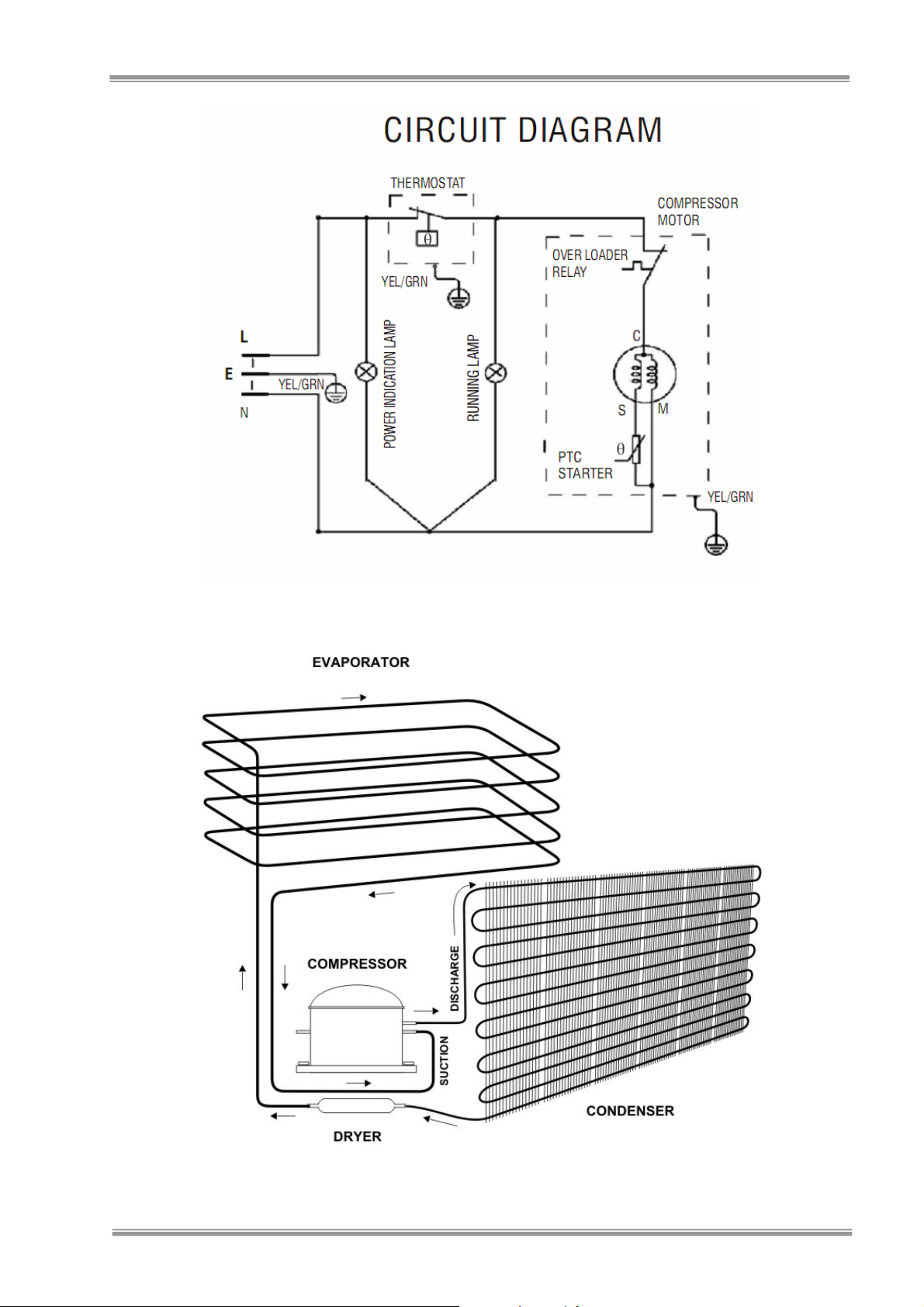
ELEC. CIRCUIT: TSD-27CF
TSD-27CF
COOLING SYSTEM
TSD-27CF
Page 4
CHEST FROZEN SHOWCASE
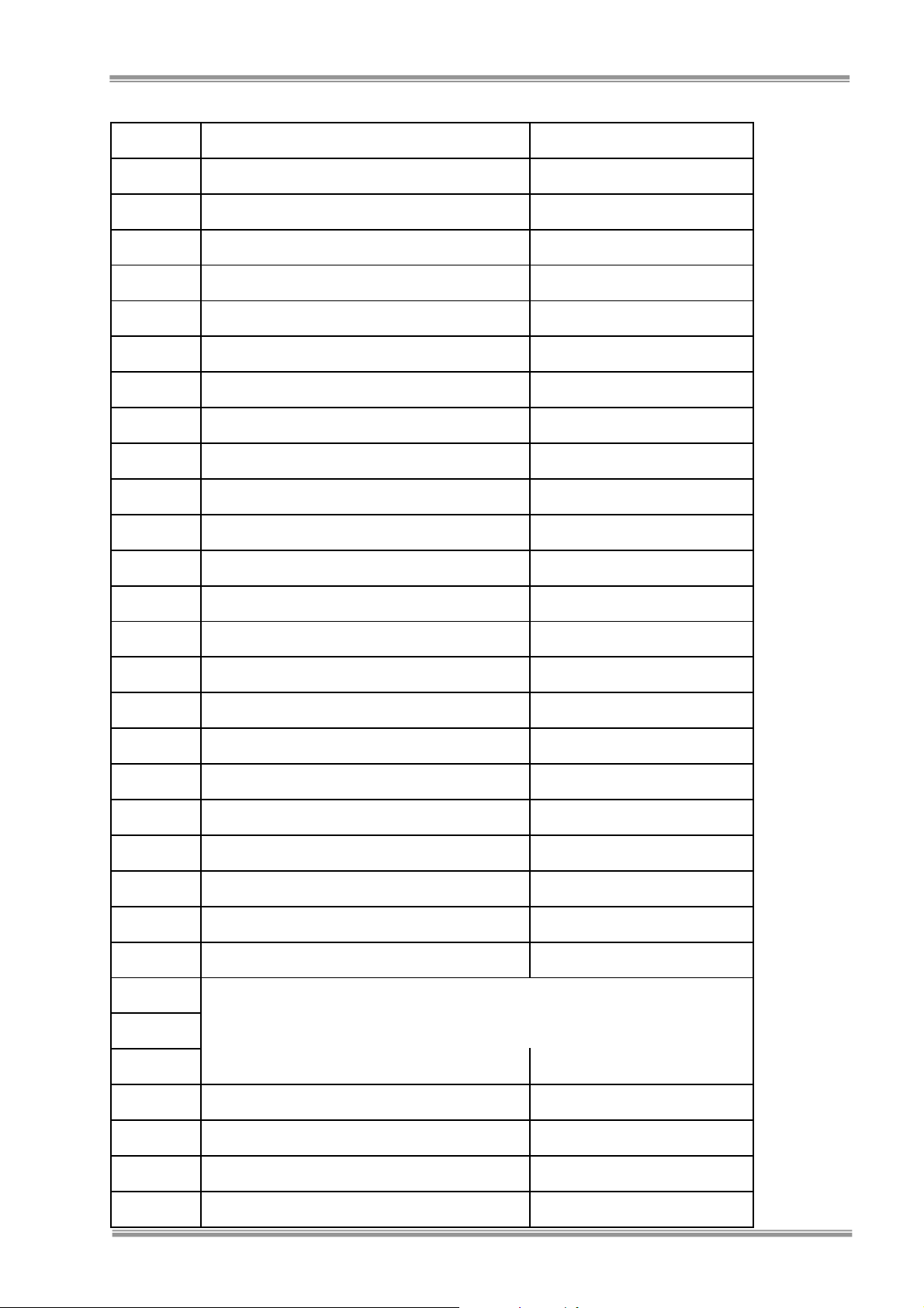
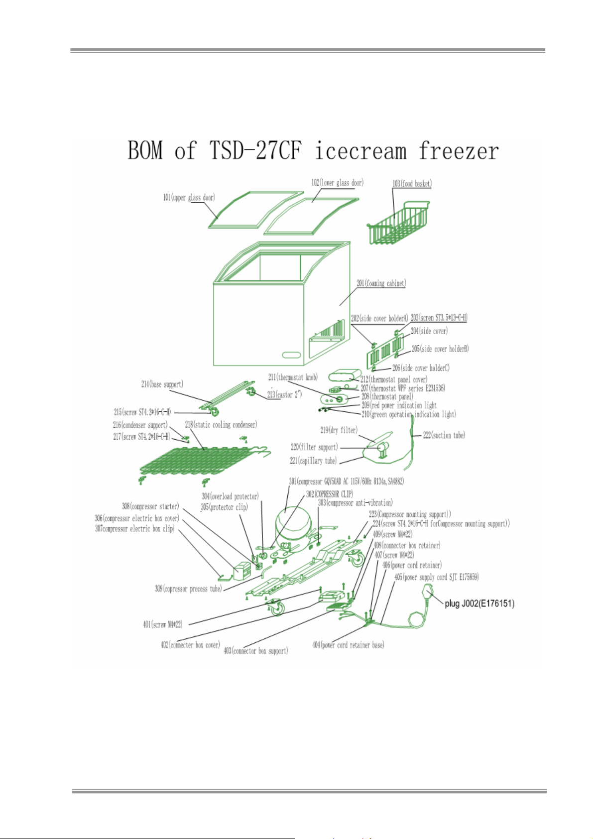
PARTS LIST of TSD-27CF
TSD-27CF
S/N Part name qty
101 Upper glass door 1
102 Lower glass door 1
103 Food basket 2
201 Foaming body 1
202 Side cover holder A 2
203 Screw ST3.5X13-C-H 2
204 Side cover 1
205 Side cover holder B 1
206 Side cover holder C 1
207 thermostat 1
208 Thermostat panel 1
209 Red indicator light 1
210 Green indicator light 1
211 Thermostat knob 1
212 Thermostat panelcover
213 Castor 2” 4
214 Base support 1
215 Screw ST4.2x16-C-H 4
216 Condenser support 4
217 Screw ST4.2x16-C-H 2
218 Condenser 1
219 Dryer filter 1
220 Dryer filter support 1
221
222
Cappilary tube
suction tube
1
1
223 Compressor support 1
301 CompressorGQY50AD 1
302 Compressor clip 2
303 Compressor anti-vibration gasket 4
304 Over load protector 1
Page 5
CHEST FROZEN SHOWCASE
TSD-27CF
305 Protector clip 1
306 Compressor electric box cover 1
307 Compressor electric box clip 1
308 PTC starter 1
309 Compressor process tube 1
401 Screw M4x22 2
402 Connector box cover 1
403 Connector box support 1
404 Power cord retainer base 1
405 Power cord 1
406 Power cord retainer 1
407 Screw M4x20 2
408 Connector box retainer 1
409 Screw M4x20 2
Page 6
Exploded View of TSD-27CF
CHEST FROZEN SHOWCASE
TSD-27CF
Page 7
CHEST FROZEN SHOWCASE
CHARACTERISTIC
TSD-27CF
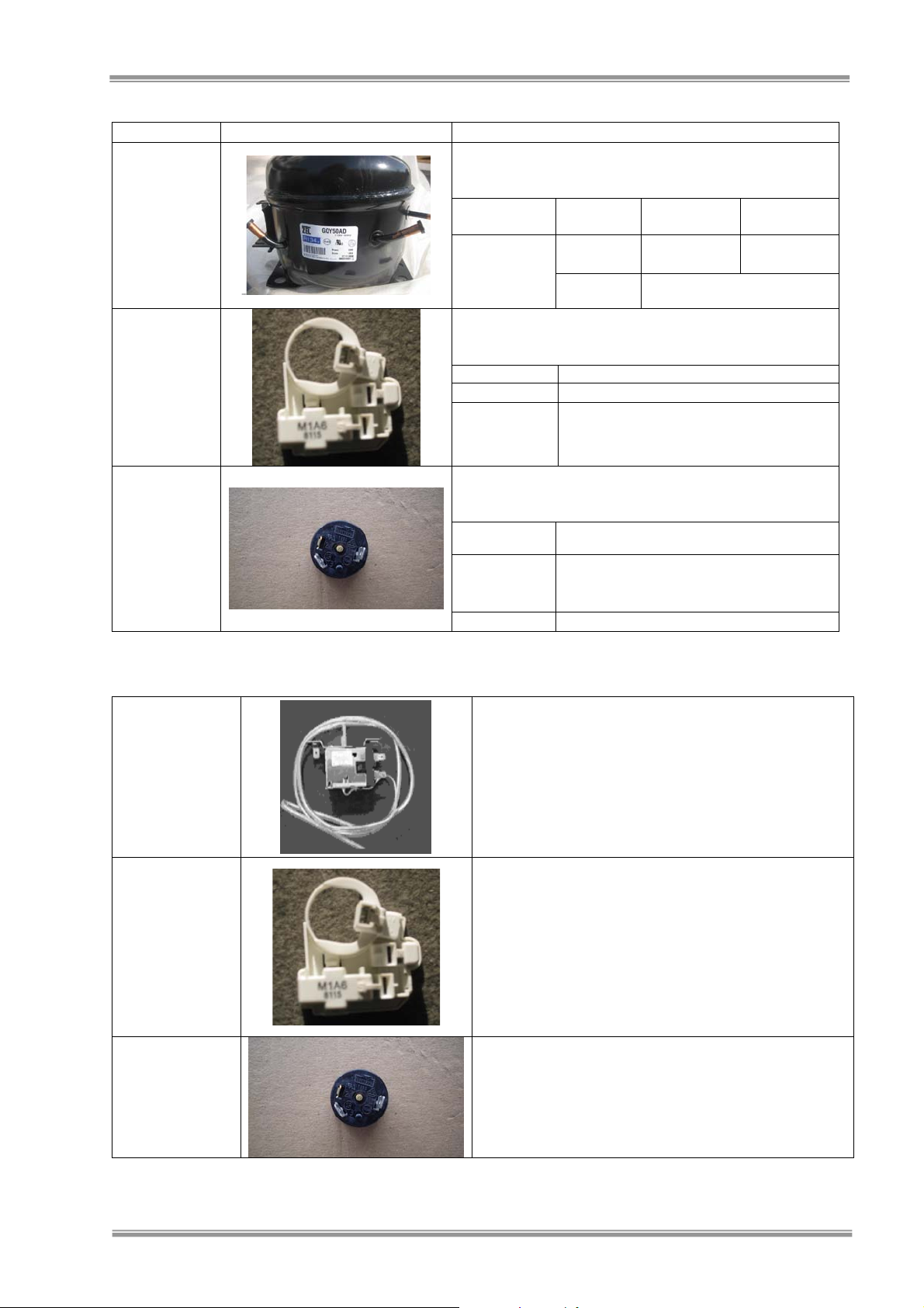
Parts Name Picture Check Method and Criterion
Measure the resistance with a tester.
Compressor
Model :TSD27CF
PTC Starter
Model : TSD27CF
Overload
Protector
Model : TSD27CF
TROUBLE SHOOTING
Thermostat
PTC Starter
Overload Protector
(Ambient temperature : Room temperature 25
Model Main Wiring
KONOR
Normal
GQY50AD
135 WATTS
Abnormal
Measure the resistance with a tester.
(Ambient temperature : Room temperature 25
Model
Normal
Abnormal
(3.8Ω~5.6Ω, Max current 18A/180V)
Open(
Measure the resistance with a tester.
(Ambient temperature : Room temperature 25
Model
T0296/74/T0296/05,B94-130-74,4TM762PBFZZ-
Less than 1
Normal
125℃ ;Close temperature:70-52℃;
current
:27A;UTC(Min action current):3.36A/70℃
Abnormal
Repair Procedure
1. Set Thermo Knob to OFF position, pull & straightened feeler
bulb
2. Remove Thermostat cover and pull out Thermostat from
Thermo Box
3. Short the thermostat terminal and check, if compressor
runs.
4. Replace thermostat
5. After replacing Thermostat, reverse steps above.
Repair Procedure
1. Release Relay Cover Fixing Clip.
2. Remove Relay Cover.
3. Remove PTC Starter
4. Pull out PTC Starter, check if open and compare value of
resistance with given value, if not
5. Hold receptacle terminal then pull electrical wire from PTC
Starter.
6. Replaces PTC Starter (change overload protector together),
reverse the steps above.
Repair Procedure
1. Check for continuity on overload protector, if open
2. Pull out Overload Protector.
3. Hold receptacle terminal then pull electrical wire from
Overload Protector.
4. Replace overload protector.
°
c)
Auxiliary
Wiring
~8Ω
7
(Approx.)S
Open( ∞ Ω ) or Short Circuited ( 0
Ω
)
°
8115PTH7M4R7MC1
∞ Ω
) or Short Circuited ( 0 Ω )
°
51(6.3)
Ω
(Approx.) Cut temperature:115-
9.9
(Approx.)S
c)
c)
~
Overload
Open(
∞ Ω
)
11.3Ω
Page 8
CHEST FROZEN SHOWCASE
TSD-27CF
Cause Check Point Correction
Repair Procedure
Compressor
Check coils
resistances
1. Replace compressor if measured resistances differ from given standard
2. Abnormal noise
Repair Procedure
1. Operate unit for 10 minutes with thermostat set at maximum
Not cooling
Check thermostat
setting
Repair Procedure
Insufficient cooling Check gasket gap
1. Check if gap can be resolved by adjustment of door hinges fixing screws.
2. Defrost if accumulation of frost is more than 10mm.
Repair Procedure
Malfunction due to
leaks or clogged
system
Charged (purge) with
nitrogen into the
refrigeration system
& check for leaks on
welds or clogs
1. Check for clog or leak in the cooling system.
2. Repair or replace the clogged or leak section.
3. Evacuate and change filter dryer.
4. Purge with nitrogen to clean and check for leaks
5. Recharge refrigerant, test run and seal system
TROUBLE INSPECTION CAUSES REMEDY
No Power
No Light
Check electric power
supply voltage
Check electrical circuit
Check lamp
Open circuit breaker or
fuse
Open Fuse Replace
Worn out or defective A/C
cord
Open Replace
Fix or replace
Replace
Check lamps socket
Low Cooling Check for thermo setting Setting too low Set thermostat higher
Defective Cooling
System
Check Overload Protector Check for continuity Replace if open.
Check leaks
Check Thermostat
Check PTC starter
resistance against given
value
Check for leaks
Check Compressor
resistance against given
specification
Check Pipe System
Corroded
Deform or warp door
gasket.
Poor weld on joints
Over storage or load or
heavy frost accumulation
Check if compressor runs
by shortening thermostat
Open, no resistance or
differ from given value
Leaks or poor welds on
joints
Defective
Clogged Pipe System or
oil choke
Replace
Adjust door hinges fixing
screws
Repair, purge with
nitrogen re-charge
refrigerant and test run.
Reduce or re-arrange
load or defrost unit
Replace thermostat if
compressor runs.
Replace PTC starter.
Repair, re-weld, purge,
evacuate and recharge
refrigerant
Replace, weld, purge,
check for leaks and recharge refrigerant, test run
and seal system
1. Evacuate then Purge
with nitrogen to remove
clogs
2. Repair or replace
clogged section, evacuate,
purge, check leak and recharge refrigerant. Test
Run and seal system
Page 9

A
SERVICE M
CHEST FREEZER
Model : TSD-35CF
NUAL
TSD-35CF
Specification: Subject to change without notice.
SPECIFICATION TSD-35CF
Classification Direct Cool, Manual Defrost, Tropical
Power Source 115VAC, 60 Hz.
Volume 208 Liters (7.3 cu.ft.)
Rated Current 3.0 Amp.
Rated Power Input 200 Watts
Power Consumption
High side /Low side
pressure
1.80 kW·h/24h
155psig/-2.22psig
Refrigerant HFC-134a (Tetrafluoroethane) CF3CH2F 160gm
Overall Dimension 895(W) x595(D) x 910(H) mm
Net Weight/Gross Weight 55 Kg./60 Kg.
ISSUED BY:
REVIEWED BY:
REVISION 2.0
Page 10

PRODUCT SPECIFICATION
CHEST FROZEN SHOWCASE
TSD-35CF
Model TSD-35CF
Classification Sliding glass Door, Direct Cool, Tropical
Color/Door White/ with Door Lock Sliding Glass
Body Finish Baked Acrylic Powder Coat
Temperature Control Thermostat
Defrost System Manual Defrost
Drain Manual Drain
Evaporator Tube Type
Condenser Tube Type
Insulation
Cabinet
Freezer Door
Rigid Polyurethane Foam (Blowing Agent CP)
Rigid Polyurethane Foam
Refrigerant HFC-134a (Tetrafluoroethane) CF3CH2F
Refrigerant Charge (gm.) 160 gm
Door Lamp None
Fan Motor None
Compressor
KONOR GQY70AD
165 Watts
Compressor Oil 290 ml.POE Polyol Ester (Synthetic)
PTC Starter
Overload Protector
11650X011 signT0296/74/T0296/05,B94-130-74,4TM762PBFZZ-51(6.3):Cut temperature:115125 ℃ ;Close temperature:70-52 ℃ ;
current):3.36A/70℃
8115PTH7M4R7MC1 (3.8Ω~5.6Ω, Max current 18A/180V)
Overload current : 27A;UTC(Min action
Dryer (Desiccant) 15 gm.
Overall Dimension (W x D x H mm.) 895(W) x595(D) x 910(H) mm
Packing Dimension (W x D x H mm.) 965 (W) x 680 (D) x 970(H) mm
Net Weight (kg.) 55kg.
Gross Weight (kg.) 60 kg.
CHARACTERISTIC
Operating Temperature (°C)
Model
Dial Position
Temperature Control
WARM 1
NORMAL 4
COLD 7
-10.0°C ± 2 °C
-15.0°C ± 2 °C
-25.0°C ± 2 °C
Page 11

CHEST FROZEN SHOWCASE
TSD-35CF
ELEC. CIRCUIT: TSD-35CF
COOLING SYSTEM
TSD-35CF
Page 12

PARTS LIST of TSD-35CF
S/N Part name qty
101 Upper glass door 1
102 Lower glass door 1
103 Food basket 2
201 Foaming body 1
202 Screw ST4.Xx16-C-H 2
203 Exhaust cover 1
204 Side cover holder A 2
205 Screw ST3.5x13-C-H 2
206 Side cover 1
207 Side cover holder B 1
208 Side cover holder C 1
209 thermostat 1
210 Thermostat panel 1
211 Red indicator light 1
212 Green indicator light 1
213 Thermostat knob 1
215 Dryer filter 1
216 Dryer filter support 1
217 Cappilary tube 1
218 suction tube 1
219 Base support 1
220 Screw ST4.2x16-C-H 4
221 Screw 4.2x16-C-H 2
222 Castor 2” 2
223 Screw ST4.2x16-C-H 2
224 Castor 2” 2
225 Screw ST4.2x16-C-H 4
226 Compressor support 1
227
228
301 compressor 1
302 Screw M6x30 4
303 washer 4
304 Over load protector 1
305 Protector clip 1
306 Compressor electric box cover 1
307 Compressor electric box clip 1
308 PTC starter 1
309 Process tube 1
310 Nut M6 4
311 Spring 4
312 Screw M5x10 2
CHEST FROZEN SHOWCASE
TSD-35CF
Fan motor support 1
Screw ST4.2x16-C-H 4
Page 13

CHEST FROZEN SHOWCASE
TSD-35CF
313 anti-vibration gasket cover 4
314 Compressor anti-vibration gasket 4
315 Nut M4 2
316 spring 2
317 Fan motor 1
318 Fan-cool condenser 1
401 Screw M4x22 2
402 Connector box cover 1
403 Connector box support 1
404 Power cord retainer base 1
405 Power cord 1
406 Power cord retainer 1
407 Screw M4x20 2
408 Connector box holder 1
409 Screw M4x20 2
Page 14

Exploded View of TSD-35CF
CHEST FROZEN SHOWCASE
TSD-35CF
Page 15

CHEST FROZEN SHOWCASE
CHARACTERISTIC
TSD-35CF
Parts Name Picture Check Method and Criterion
Measure the resistance with a tester.
Compressor
Model :TSD35CF
PTC Starter
Model : TSD35CF
Overload
Protector
Model : TSD35CF
TROUBLE SHOOTING
Thermostat
PTC Starter
Overload Protector
(Ambient temperature : Room temperature 25
Model Main Wiring
KONOR
Normal
GQY70AD
164 WATTS
Abnormal
Measure the resistance with a tester.
(Ambient temperature : Room temperature 25
Model
Normal
Abnormal
Open(
8115PTH7M4R7MC1
(3.8Ω~5.6Ω, Max current 18A/180V)
∞ Ω
Measure the resistance with a tester.
(Ambient temperature : Room temperature 25
Model
Normal
T0296/74/T0296/05,B94-130-74,4TM762PBFZZ-
Less than 1
125℃ ;Close temperature:70-52℃;Overload
current
Ω
:27A;UTC(Min action current):3.36A/70℃
Abnormal
Repair Procedure
1. Set Thermo Knob to OFF position, pull & straightened feeler
bulb
2. Remove Thermostat cover and pull out Thermostat from
Thermo Box
3. Short the thermostat terminal and check, if compressor
runs.
4. Replace thermostat
5. After replacing Thermostat, reverse steps above.
Repair Procedure
1. Release Relay Cover Fixing Clip.
2. Remove Relay Cover.
3. Remove PTC Starter
4. Pull out PTC Starter, check if open and compare value of
resistance with given value, if not
5. Hold receptacle terminal then pull electrical wire from PTC
Starter.
6. Replaces PTC Starter (change overload protector together),
reverse the steps above.
Repair Procedure
1. Check for continuity on overload protector, if open
2. Pull out Overload Protector.
3. Hold receptacle terminal then pull electrical wire from
Overload Protector.
4. Replace overload protector.
°
c)
Auxiliary
Wiring
~
2.9
2.5
Ω
(Approx.)S
Open( ∞ Ω ) or Short Circuited ( 0
Ω
)
°
4.1
(Approx.)S
c)
~
4.7Ω
) or Short Circuited ( 0 Ω )
°
c)
51(6.3)
(Approx.) Cut temperature:115-
Open(
∞ Ω
)
Page 16

CHEST FROZEN SHOWCASE
TSD-35CF
Cause Check Point Correction
Repair Procedure
Compressor
Check coils
resistances
1. Replace compressor if measured resistances differ from given standard
2. Abnormal noise
Repair Procedure
1. Operate unit for 10 minutes with thermostat set at maximum
Not cooling
Check thermostat
setting
Repair Procedure
Insufficient cooling Check gasket gap
1. Check if gap can be resolved by adjustment of door hinges fixing screws.
2. Defrost if accumulation of frost is more than 10mm.
Repair Procedure
Malfunction due to
leaks or clogged
system
Charged (purge) with
nitrogen into the
refrigeration system
& check for leaks on
welds or clogs
1. Check for clog or leak in the cooling system.
2. Repair or replace the clogged or leak section.
3. Evacuate and change filter dryer.
4. Purge with nitrogen to clean and check for leaks
5. Recharge refrigerant, test run and seal system
TROUBLE INSPECTION CAUSES REMEDY
No Power
No Light
Check electric power
supply voltage
Check electrical circuit
Check lamp
Open circuit breaker or
fuse
Open Fuse Replace
Worn out or defective A/C
cord
Open Replace
Fix or replace
Replace
Check lamps socket
Low Cooling Check for thermo setting Setting too low Set thermostat higher
Defective Cooling
System
Check Overload Protector Check for continuity Replace if open.
Check leaks
Check Thermostat
Check PTC starter
resistance against given
value
Check for leaks
Check Compressor
resistance against given
specification
Check Pipe System
Corroded
Deform or warp door
gasket.
Poor weld on joints
Over storage or load or
heavy frost accumulation
Check if compressor runs
by shortening thermostat
Open, no resistance or
differ from given value
Leaks or poor welds on
joints
Defective
Clogged Pipe System or
oil choke
Replace
Adjust door hinges fixing
screws
Repair, purge with
nitrogen re-charge
refrigerant and test run.
Reduce or re-arrange
load or defrost unit
Replace thermostat if
compressor runs.
Replace PTC starter.
Repair, re-weld, purge,
evacuate and recharge
refrigerant
Replace, weld, purge,
check for leaks and recharge refrigerant, test run
and seal system
1. Evacuate then Purge
with nitrogen to remove
clogs
2. Repair or replace
clogged section, evacuate,
purge, check leak and recharge refrigerant. Test
Run and seal system
Page 17

A
SERVICE M
CHEST FREEZER
Model : TSD-47CF/TSD-60CF
NUAL
TSD-47CF/TSD-60CF
Specification: Subject to change without notice.
SPECIFICATION TSD-47CF TSD-60CF
Classification Direct Cool, Manual Defrost, Tropical
Power Source 115VAC, 60 Hz.
Volume 298 Liters (10.5 cu.ft.) 318 Liters (11.2 cu.ft.)
Rated Current 2.5 Amp.
Rated Power Input 270 Watts
Power Consumption
High side /Low side
pressure
3.2 kW·h/24h 3.5 kW·h/24h
155psig/-2.22psig
Refrigerant HFC-134a (Tetrafluoroethane) CF3CH2F 215gm
Overall Dimension 1215(W) x600(D) x 910(H) mm 1295(W) x600(D) x 910(H) mm
Net Weight/Gross Weight 62 Kg./73 Kg. 64 Kg./75 Kg.
ISSUED BY:
REVIEWED BY:
REVISION 2.0
Page 18

PRODUCT SPECIFICATION
CHEST FROZEN SHOWCASE
TSD-47CF/TSD-60CF
Model TSD-47CF TSD-60CF
Classification Sliding glass Door, Direct Cool, Tropical
Color/Door White/ with Door Lock Sliding Glass
Body Finish Baked Acrylic Powder Coat
Temperature Control Thermostat
Defrost System Manual Defrost
Drain Manual Drain
Evaporator Tube Type
Condenser Tube Type+Fan-cooling Condenser
Insulation
Cabinet
Freezer Door
Rigid Polyurethane Foam (Blowing Agent CP)
Rigid Polyurethane Foam
Refrigerant HFC-134a (Tetrafluoroethane) CF3CH2F
Refrigerant Charge (gm.) 215 gm
Door Lamp None
Fan Motor ZCF-200(100V-125V/60Hz)
Compressor
DONPER EU1121BZ
160 Watts
Compressor Oil 290 ml.POE Polyol Ester (Synthetic)
PTC Starter
QP2-4.7C
Overload Protector B85-105(220VAC 1.5A-15A 80℃-140℃)
compressor capacity CBB60(15µF ±5%C,250V.AC 50/60Hz)
Dryer (Desiccant) 20 gm.
Overall Dimension (W x D x H mm.) 1215(W) x600(D) x 910(H) mm 1295(W) x600(D) x 910(H) mm
Packing Dimension (W x D x H mm.) 1270(W) x680(D) x 980(H) mm 1355(W) x680(D) x 980(H) mm
Net Weight (kg.) 62kg. 64kg.
Gross Weight (kg.) 73 kg. 75 kg.
CHARACTERISTIC
Operating Temperature (°C)
Model
Dial Position
Temperature Control
WARM 1
NORMAL 4
COLD 7
-10.0°C ± 2 °C
-15.0°C ± 2 °C
-25.0°C ± 2 °C
Page 19

CHEST FROZEN SHOWCASE
TSD-47CF/TSD-60CF
ELEC. CIRCUIT: TSD-47CF/TSD-60CF
COOLING SYSTEM
TSD-47CF/TSD-60CF
Page 20

CHEST FROZEN SHOWCASE
PARTS LIST of TSD-47CF/TSD-60CF
TSD-47CF/TSD-60CF
S/N Part name qty
101 Upper glass door 1
102 Lower glass door 1
103 Food basket 4
201 Foaming body 1
202 Screw ST4.Xx16-C-H 2
203 Exhaust cover 1
204 Side cover holder A 2
205 Screw ST3.5x13-C-H 2
206 Side cover 1
207 Side cover holder B 1
208 Side cover holder C 1
209 thermostat 1
210 Thermostat panel 1
211 Red indicator light 1
212 Green indicator light 1
213 Thermostat knob 1
215 Dryer filter 1
216 Dryer filter support 1
217
218
Cappilary tube
suction tube
1
1
219 Base support 1
220 Screw ST4.2x16-C-H 4
221 Screw 4.2x16-C-H 2
222 Castor 2” 2
223 Screw ST4.2x16-C-H 2
224 Castor 2” 2
225 Screw ST4.2x16-C-H 4
226 Compressor support 1
227
228
Fan motor support 1
Screw ST4.2x16-C-H 4
301 Compressor EU1121BZ 1
302 Screw M6x30 4
Page 21

CHEST FROZEN SHOWCASE
TSD-47CF/TSD-60CF
303 washer 4
304 Over load protector 1
305 Protector clip 1
306 Compressor electric box cover 1
307 Compressor electric box clip 1
308 PTC starter 1
309 Process tube 1
310 Nut M6 4
311 Spring 4
312 Screw M5x10 2
313 anti-vibration gasket cover 4
314 Compressor anti-vibration gasket 4
315 Nut M4 2
316 spring 2
317 Fan motor ZCF-200 1
318 Fan-cool condenser 1
401 Screw M4x22 2
402 Connector box cover 1
403 Connector box support 1
404 Power cord retainer base 1
405 Power cord 1
406 Power cord retainer 1
407 Screw M4x20 2
408 Connector box holder 1
409 Screw M4x20 2
Page 22

Exploded View of TSD-47CF
CHEST FROZEN SHOWCASE
TSD-47CF/TSD-60CF
Page 23

Exploded View of TSD-60CF
CHEST FROZEN SHOWCASE
TSD-47CF/TSD-60CF
Page 24

CHEST FROZEN SHOWCASE
CHARACTERISTIC
TSD-47CF/TSD-60CF
Parts Name Picture Check Method and Criterion
Compressor
Model :TSD47CF/TSD60CF
Measure the resistance with a tester.
(Ambient temperature : Room temperature 25
Model Main Wiring
~
2.9
DONPER
EU1121BZ
160 WATTS
Normal
Abnormal
2.5
(Approx.)S
Open( ∞ Ω ) or Short Circuited ( 0
Ω
)
Measure the resistance with a tester.
°
c)
Auxiliary
Wiring
Ω
4.1
~
4.7Ω
(Approx.)S
PTC Starter
Model : TSD47CF/TSD60CF
Overload
Protector
Model : TSD47CF/TSD60CF
compressor
capacity
TROUBLE SHOOTING
Thermostat
PTC Starter
(Ambient temperature : Room temperature 25
Model
Normal
Abnormal
(3.8Ω~5.6Ω, Max current 18A/180V)
Open(
∞ Ω
) or Short Circuited ( 0 Ω )
°
QP2-4.7C
c)
Measure the resistance with a tester.
(Ambient temperature : Room temperature 25
Model
Less than 1
Normal
current
Abnormal
Ω
(Approx.) Cut temperature:115-125
℃ ;Close temperature:70-52℃;
:27A;UTC(Min action current):3.36A/70℃
Open(
B85-105
∞ Ω
°
c)
Overload
)
Measure the resistance with a tester.
(Ambient temperature : Room temperature 25
Model
CBB60(15µF ±5%C,250V.AC 50/60Hz)
°
c)
Normal
Abnormal
Open(
∞ Ω
)
Repair Procedure
1. Set Thermo Knob to OFF position, pull & straightened feeler
bulb
2. Remove Thermostat cover and pull out Thermostat from
Thermo Box
3. Short the thermostat terminal and check, if compressor runs.
4. Replace thermostat
5. After replacing Thermostat, reverse steps above.
Repair Procedure
1. Release Relay Cover Fixing Clip.
2. Remove Relay Cover.
3. Remove PTC Starter
4. Pull out PTC Starter, check if open and compare value of
resistance with given value, if not
5. Hold receptacle terminal then pull electrical wire from PTC
Starter.
6. Replaces PTC Starter (change overload protector together),
reverse the steps above.
Page 25

CHEST FROZEN SHOWCASE
TSD-47CF/TSD-60CF
Repair Procedure
1. Check for continuity on overload protector, if open
Overload Protector
2. Pull out Overload Protector.
3. Hold receptacle terminal then pull electrical wire from Overload
Protector.
4. Replace overload protector.
Cause Check Point Correction
Repair Procedure
Compressor
Check coils
resistances
1. Replace compressor if measured resistances differ from given standard
2. Abnormal noise
Repair Procedure
1. Operate unit for 10 minutes with thermostat set at maximum
Not cooling
Check thermostat
setting
Repair Procedure
Insufficient cooling Check gasket gap
1. Check if gap can be resolved by adjustment of door hinges fixing screws.
2. Defrost if accumulation of frost is more than 10mm.
Repair Procedure
Malfunction due to
leaks or clogged
system
Charged (purge) with
nitrogen into the
refrigeration system
& check for leaks on
welds or clogs
1. Check for clog or leak in the cooling system.
2. Repair or replace the clogged or leak section.
3. Evacuate and change filter dryer.
4. Purge with nitrogen to clean and check for leaks
5. Recharge refrigerant, test run and seal system
TROUBLE INSPECTION CAUSES REMEDY
No Power
No Light
Check electric power
supply voltage
Check electrical circuit
Check lamp
Open circuit breaker or
fuse
Open Fuse Replace
Worn out or defective A/C
cord
Open Replace
Fix or replace
Replace
Check lamps socket
Low Cooling Check for thermo setting Setting too low Set thermostat higher
Defective Cooling
System
Check Overload Protector Check for continuity Replace if open.
Check leaks
Check Thermostat
Check PTC starter
resistance against given
value
Check for leaks
Check Compressor
resistance against given
specification
Check Pipe System
Corroded
Deform or warp door
gasket.
Poor weld on joints
Over storage or load or
heavy frost accumulation
Check if compressor runs
by shortening thermostat
Open, no resistance or
differ from given value
Leaks or poor welds on
joints
Defective
Clogged Pipe System or 1. Evacuate then Purge
Replace
Adjust door hinges fixing
screws
Repair, purge with
nitrogen re-charge
refrigerant and test run.
Reduce or re-arrange
load or defrost unit
Replace thermostat if
compressor runs.
Replace PTC starter.
Repair, re-weld, purge,
evacuate and recharge
refrigerant
Replace, weld, purge,
check for leaks and recharge refrigerant, test run
and seal system
Page 26

CHEST FROZEN SHOWCASE
TSD-47CF/TSD-60CF
oil choke with nitrogen to remove
clogs
2. Repair or replace
clogged section, evacuate,
purge, check leak and recharge refrigerant. Test
Run and seal system
 Loading...