

Page 1
Bakery Case Service Manual
Bakery Case Service Manual
Bakery Case Service Manual
Bakery Case Service Manual
Bakery Case Service Manual
Bakery Case Service Manual
Bakery Case Service Manual
Bakery Case Service Manual
(Model : TCB-5R)
(Model : TCB-5R)
(Model : TCB-5R)
(Model : TCB-5R)
(Model : TCB-5R)
(Model : TCB-5R)
(Model : TCB-5R)
(Model : TCB-5R)
Page 2

Table of Contens
3-5. Front Motor Assembly
r
y
5-2. Function Table
1. Feature Chart
1-1. Front View
1-2. Side View
1-3. Rear View
2. Wiring Diagram
3. Part Details
3-1. Refrigeration Compartment
3-2. Cooling Compartment
3-3. Control Compartment
3-4. Lamp Assembly
-
3-6. Case Drain Assy
4. Main Components
4-1. Compressor
4-2. Liquid Line Filte
4-3. Evaporator Fan Motor
4-4. Condenser Fan Motor
4-5. Condenser Fan Blade
4-6. Evaporatorr Fan Blade
4-7. Power & Light switch
4-8. Ballast
4-9. Lamp(Fluorescent)
4-10. Lamp Socket
4-11. PCB Assy
4-12. Trans Former(Down Trans)
5. Electic Temperature Control Instruction
5-1. How to use the display PCB Panel
-
5-3. Function Table
1
Page 3

6. Trouble Shooting Chart
6 4. When there is a excessive noise
8-1. Side Glass Part
6-1. The refrigerator does not cooling
6-2. The refrigerator does not cooling well
6-3. Lamp does not light well
6-4. When there is a excessive noise
7. Refrigerant Cycle Diagram
8. Replacement of Main Components
8-2. Front Glass Part
8-3.Top Lamp Assy Part
8-4.Wire Shelf Lamp Assy Part
8-5.Front Motor Assy Part
9. Parts List
2
Page 4
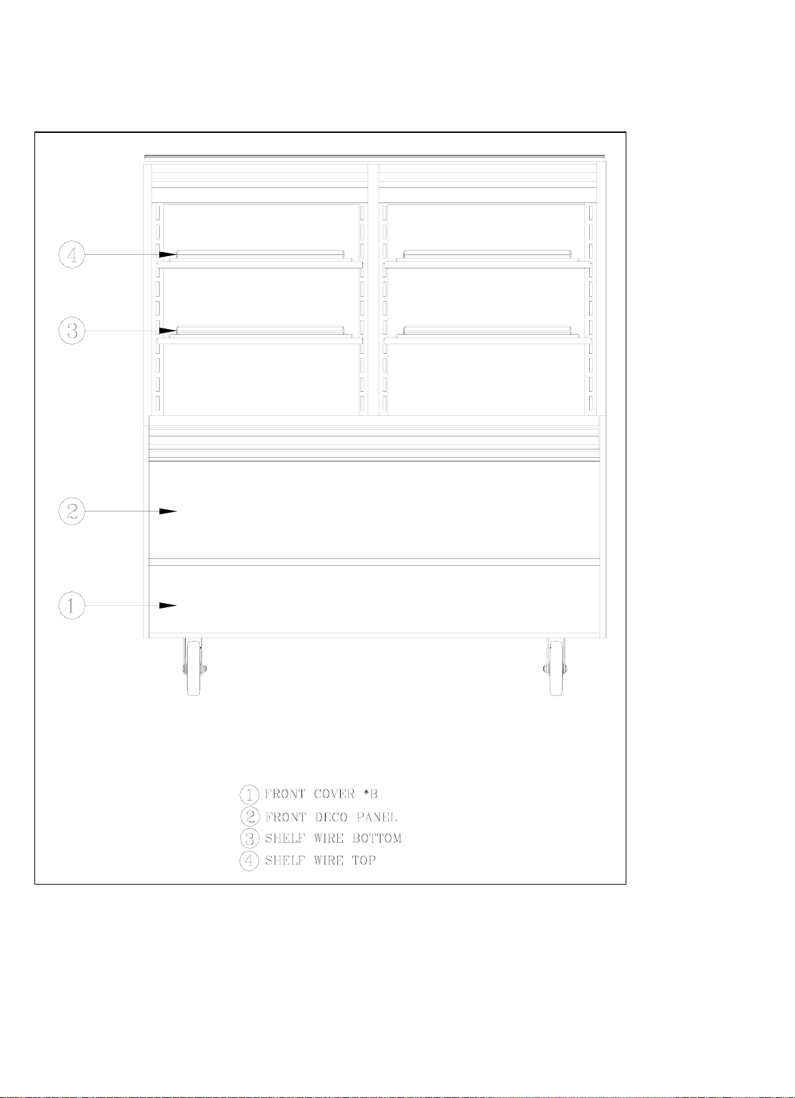
1. Feature Chart
1-1. Front View
3
Page 5
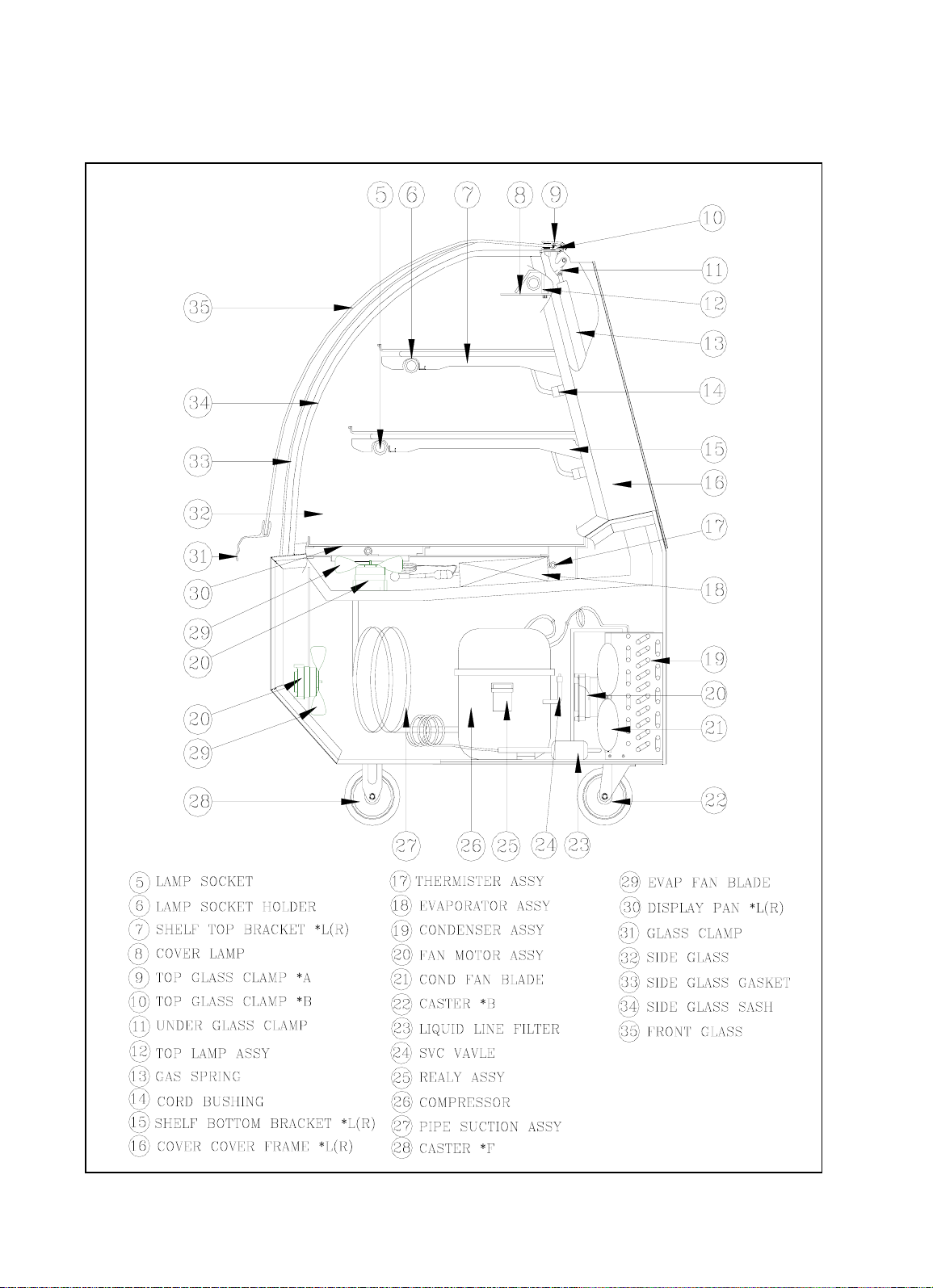
1-2. Side View
4
Page 6
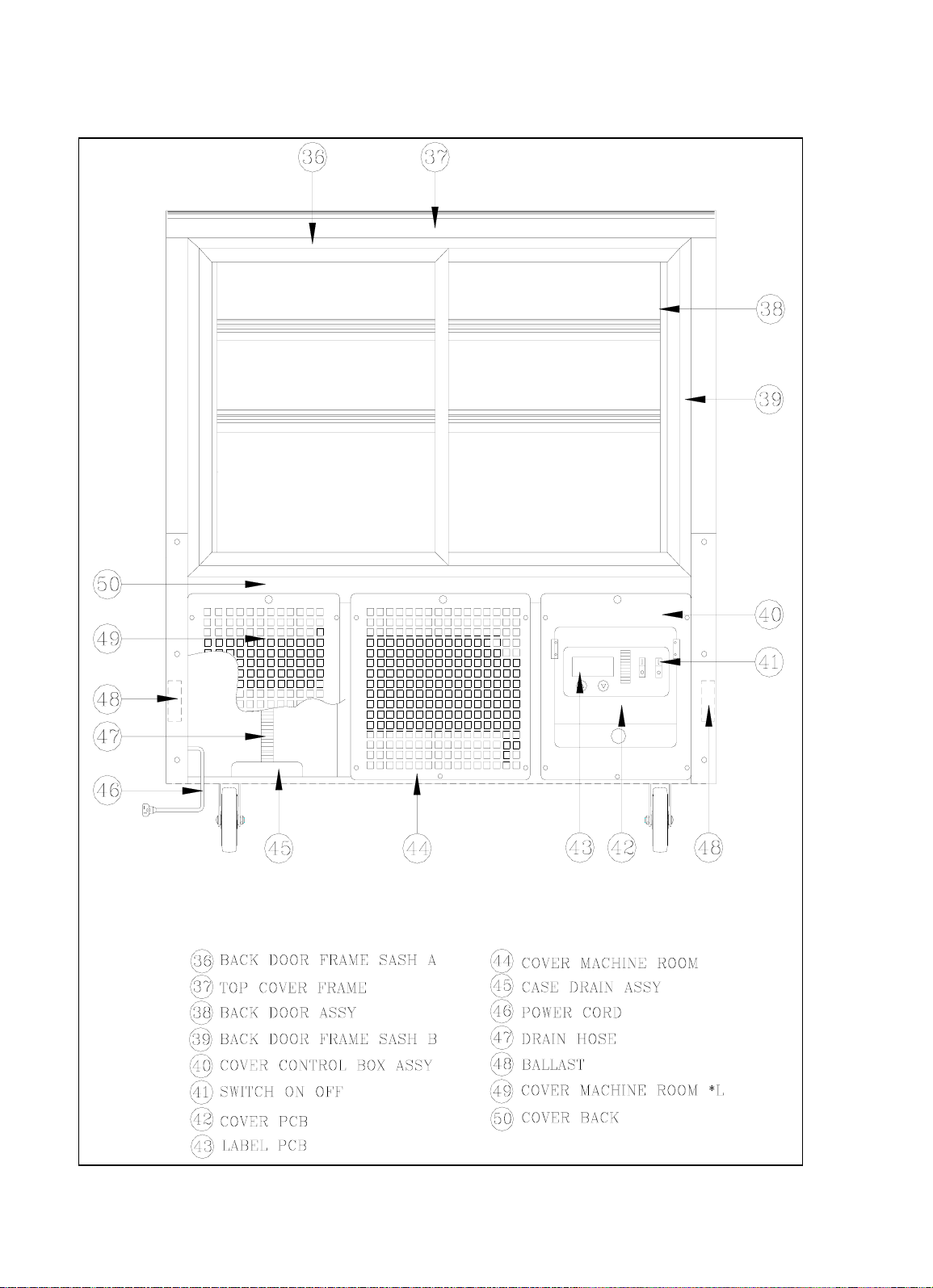
1-3. Rear View
5
Page 7
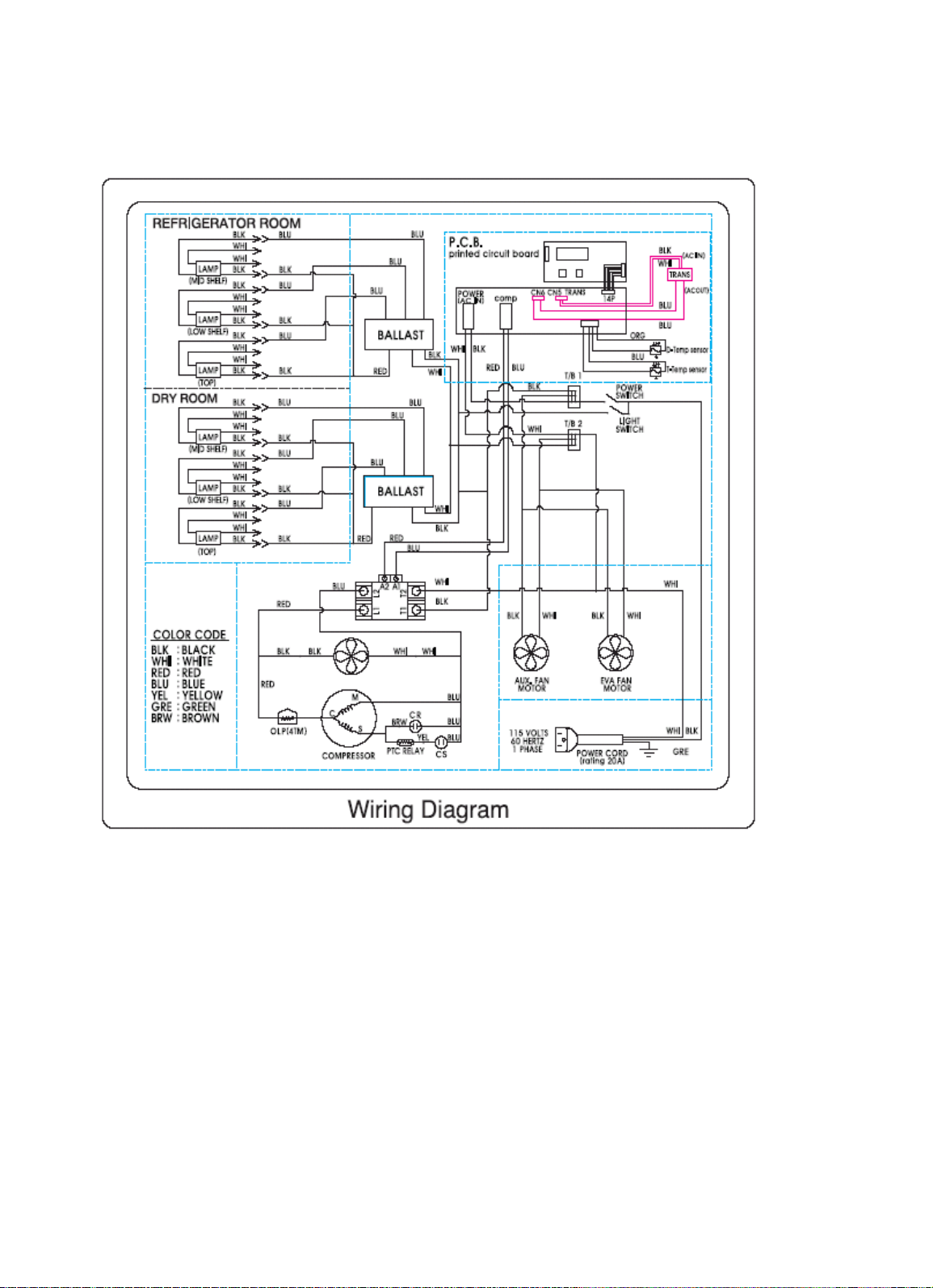
2. Wiring Diagram
6
Page 8
3. Part Details
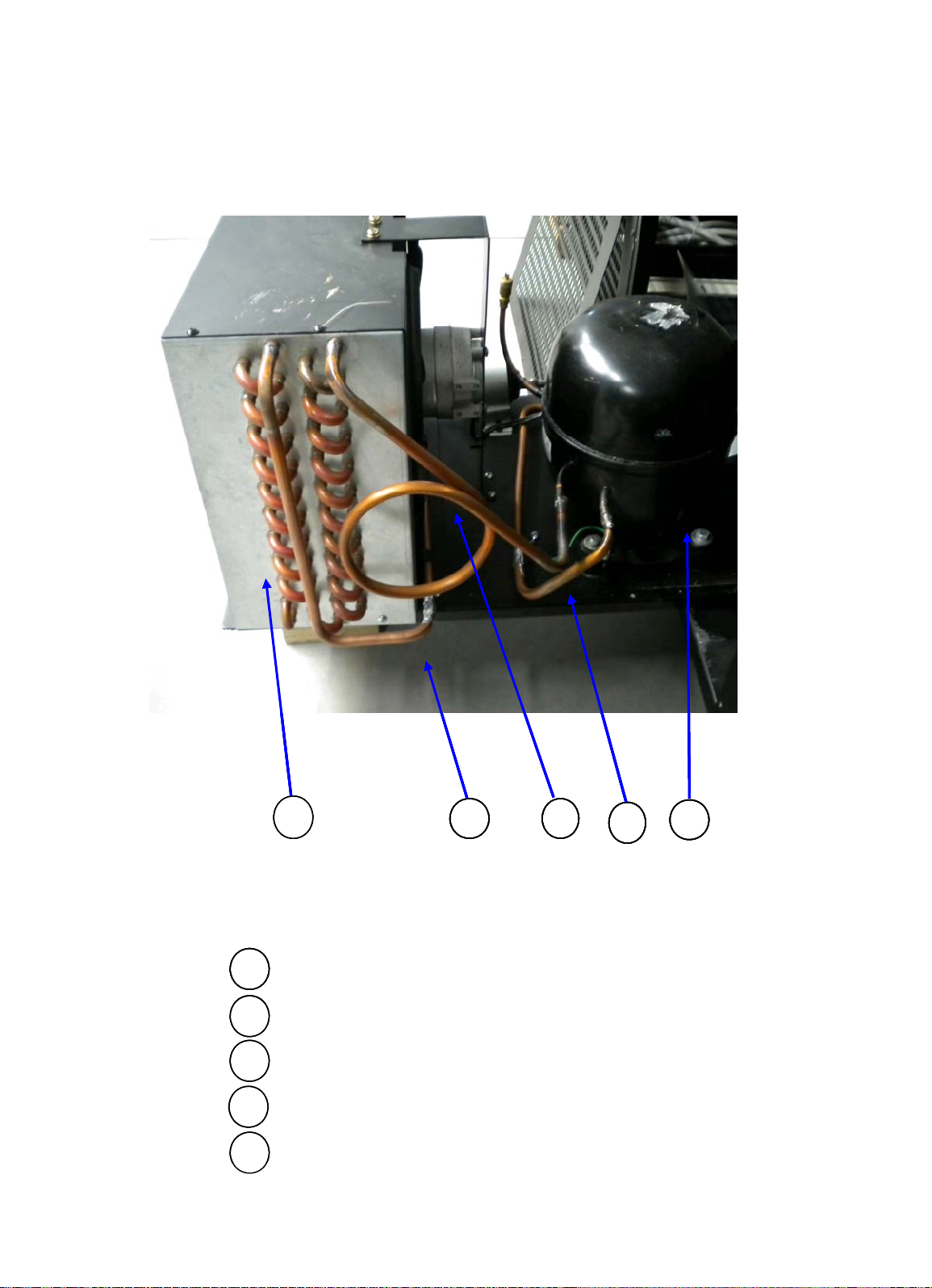
PIPE CONNNECT SUCTION
3-1. Refrigeration Compartment
19
19
19
19
CONDENSER ASSY
19
19
19
COMPRESSOR
26
26
PIPE CONDENSER OUT
51
51
PIPE COMRESSOR OUT
52
52
53
53
52
52
52
52
7
53
53
53
53
2651
2651
2651
2651
Page 9
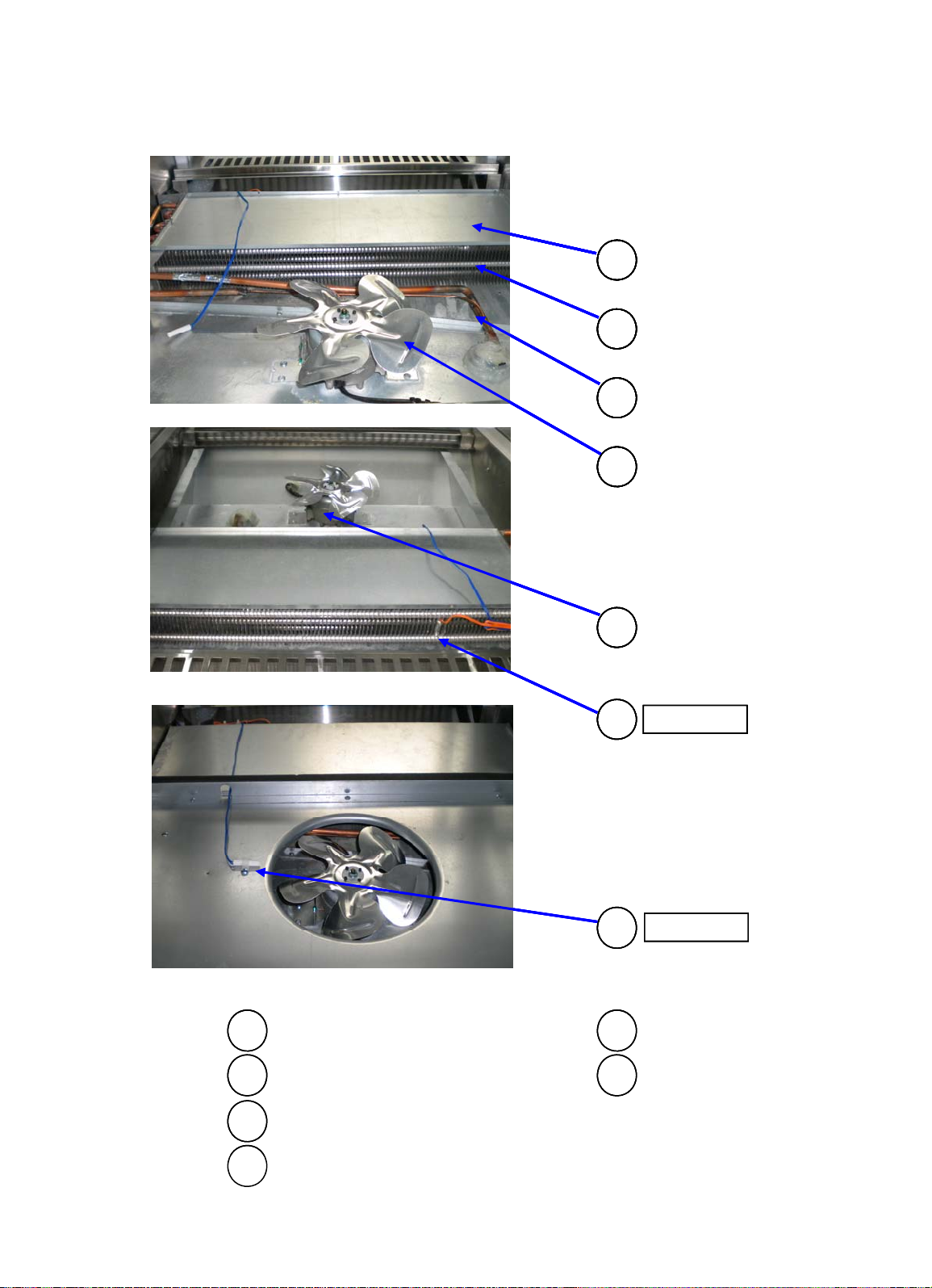
3-2. Cooling Compartment
54
54
54
54
54
54
185418
18
18
18
18
18
27
27
27
27
27
27
29
29
29
29
29
29
20
20
20
20
20
D-Sensor
D-Sensor
D-Sensor
54
54
D-Sensor
T-Sensor
T-Sensor
T-Sensor
17
17
17
17
17
17
17
THERMISTER ASSY(D-SENSOR) EVAP FAN BLADE
17
17
EVAPORATOR ASSY COVER EVAPORATOR
18
18
32
32
FAN MOTOR ASSY
20
20
27
PIPE SUCTION ASSY
8
Page 10
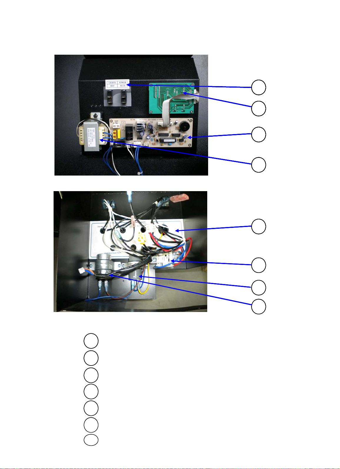
3-3. Control Compartment
55
55
55
55
55
55
55
56
56
56
56
56
56
56
56
56
56
56
56
56
56
57
57
57
57
57
57
LABEL SWITCH
55
55
55
PCB ASSY
56
56
56
DOWN TRANS
57
57
LABEL CONTROL BOX
58
58
58
58
58
58
58
59
59
59
59
60
60
60
60
61
61
61
61
SWITCH MAGNETIC CONNECTER
59
59
CAPACITOR STARTING
60
CAPACITOR RUNNING
61
9
Page 11

3-4. Top Lamp Assy
LAMP SOCKET
63
63
62
62
62
5
5
5
LAMP SOCKET HOLDER
6
6
LAMP
62
62
63
63
TUBE LAMP
SCREW MACHINE
64
LAMP CLIP
65
63
64
64
64
65
65
65
5
5
6
6
6
5
10
Page 12

3-5. Front Motor Assembly
66
66
66
66
66
20
20
29
29
67
67
67
67
67
20
20
20
20
20
FAN MOTOR ASSY SCREW MACHINE
EVAP FAN BLADE PACKING MOTOR
68 29
68 29
68 29
68 29
68 29
69
69
70
70
69
69
69
69
69
70
70
70
70
71
71
71
71
72
72
72
66
66
67
68
BRAKET FRONT MOTOR NUT MOTOR
COVER FRONT MOTOR *L WASHER MOTOR
SCREW MACHINE
71
71
72
11
Page 13

3-6. Case Drain Assy
CASE DRAIN
73
73
73
73
HOLDER PAPER
74
PLATE VAPORI PAPER
75
74
74
75
75
12
Page 14

4. Main Components
g
g
4-2. Liquid Line Filter
Qty
1
1
4-1. Compressor
Model
Refrigerant
Volta
Comp Model
Part Code
Starting Type
Model TB-5R TCB-5R
Refrigerant R-134a
Pressure Min 667psig
Model DML0535
Part Code MSC4401300
4-3. Evaporator Fan Motor
e
MSC1300100
TB-5R TCB-5R
R-134a
115V 60Hz
CAJ447Y
CSIR
SK1A1C-L2W
MSC1300200
Remark
←
←
CSR
Remark
←
←
←
←
Model TB-5R TCB-5R
Voltage 115V 60Hz , 9W
Model SE-046
Q'ty 3 2
Type CW
Part Code MSC1800300
4-4. Condenser Fan Motor
Model TB-5R TCB-5R
Voltage 115V 60Hz , 16W 115V 60Hz , 9W
Model SE-083 SE-046
'
Type CW
Part Code MSC1800400 MSC1800300
Remark
←
←
←
←
Remark
←
4-5. Condenser Fan Blade
13
Page 15

Model TB-5R TCB-5R
Part Code
MSC1800200
Specification
Φ200 4B
←
g
A
Rating
120V 770mA
Remark
Metal Aluminum
Specification Φ250 4B
Type CW
Part Code MSC1800200
4-6. Evaporatorr Fan Blade
Model TB-5R TCB-5R
Metal Aluminum
Q'ty 3 2
Type CW
Part Code MSC1800100
4-7. Power & Light switch
Model TB-5R TCB-5R
←
←
←
←
Remark
←
←
←
Remark
Marked "I" and "O"
Rating 125V 15A
Model RL1-3
Part Code MSC8100200
4-8. Ballast
Model TB-5R TCB-5R
Ratin
Model TP120-3/32IS
Q'ty 1 2
Part Code MSC3600300
120V 770m
←
←
←
←
Remark
←
←
←
14
Page 16

4-9. Lamp(Fluorescent)
/
Model
FLR32SS 865
FL20SS/18D
Remark
Model
TB-5R
TCB-5R
g
Rating
115V/60Hz
Model TB-5R TCB-5R
Rating 32W 18W
Model FLR32SS 865 FL20SS
Q'ty 3 6
Part Code MSC3600500 MSC3600400
4-10. Lamp Socket
Rating 250V 2A
Model JS-103
Q'ty 6 12
Part Code MSC3600100
4-11. PCB Assy
Model TB-5R TCB-5R
Remark
18D
←
←
←
Remark
Rating 115V/60Hz
Specification Bakery-A9-6H
Part Code MSC4300100
4-12. Trans Former(Down Trans)
Model TB-5R TCB-5R
Ratin
Model DWS-1310U
Part Code MSC8400100
115V/60Hz
←
←
←
Remark
←
←
←
15
Page 17

5. Electric Temperature Control Instruction
5-1. Refrigerator Control
5-1-1. How to use the display PCB Panel
- LED
- It indicates setting temperature.
COOL
COOL
COOL
COOL
COOL
COOL
COOL
COOL
NORMAL
NORMAL
NORMAL
NORMAL
NORMAL
NORMAL
NORMAL
NORMAL
COLD
COLD
COLD
COLD
COLD
COLD
COLD
COLD
TEMPERATURE
TEMPERATURE
TEMPERATURE
TEMPERATURE
TEMPERATURE
TEMPERATURE
TEMPERATURE
TEMPERATURE
BAKERY SHOW CASE
BAKERY SHOW CASE
BAKERY SHOW CASE
BAKERY SHOW CASE
BAKERY SHOW CASE
BAKERY SHOW CASE
BAKERY SHOW CASE
BAKERY SHOW CASE
F
F
F
F
F
F
F
F
- Temperature can be controlled by the user.
POWER LIGHTS
POWER LIGHTS
POWER LIGHTS
POWER LIGHTS
POWER LIGHTS
POWER LIGHTS
POWER LIGHTS
POWER LIGHTS
REFRIGERATOR MANUFACTURER
REFRIGERATOR MANUFACTURER
REFRIGERATOR MANUFACTURER
REFRIGERATOR MANUFACTURER
REFRIGERATOR MANUFACTURER
REFRIGERATOR MANUFACTURER
REFRIGERATOR MANUFACTURER
REFRIGERATOR MANUFACTURER
- Factory setting is level "NORMAL". Setting can be changed by pressing
up/down button.
5-1-2. Error Code
Code
Code
Code
Code
Code
Code
Code
Code
TE
TE
TE
TE
TE
TE
TE
TE
CE
CE
CE
CE
CE
CE
CE
CE
Content
Content
Content
Content
Content
Content
Content
Content
T-Sensor
T-Sensor
T-Sensor
T-Sensor
T-Sensor
T-Sensor
T-Sensor
T-Sensor
C-Sensor
C-Sensor
C-Sensor
C-Sensor
C-Sensor
C-Sensor
C-Sensor
C-Sensor
Perception Method
Perception Method
Perception Method
Perception Method
Perception Method
Perception Method
Perception Method
Perception Method
Open
Open
Open
Open
Open
Open
Open
Open
Short
Short
Short
Short
Short
Short
Short
Short
Open
Open
Open
Open
Open
Open
Open
Open
Short
Short
Short
Short
Short
Short
Short
Short
Refrigeration state
Refrigeration state
Refrigeration state
Refrigeration state
Refrigeration state
Refrigeration state
Refrigeration state
Refrigeration state
- NORMAL operation
- NORMAL operation
- NORMAL operation
- NORMAL operation
- NORMAL operation
- NORMAL operation
- NORMAL operation
- NORMAL operation
- Time Control
- Time Control
- Time Control
- Time Control
- Time Control
- Time Control
- Time Control
- Time Control
Compressor ON : 10Minutes
Compressor ON : 10Minutes
Compressor ON : 10Minutes
Compressor ON : 10Minutes
Compressor ON : 10Minutes
Compressor ON : 10Minutes
Compressor ON : 10Minutes
Compressor ON : 10Minutes
Compressor OFF : 10Minutes
Compressor OFF : 10Minutes
Compressor OFF : 10Minutes
Compressor OFF : 10Minutes
Compressor OFF : 10Minutes
Compressor OFF : 10Minutes
Compressor OFF : 10Minutes
Compressor OFF : 10Minutes
Maintain normal operation
Maintain normal operation
Maintain normal operation
Maintain normal operation
Maintain normal operation
Maintain normal operation
Maintain normal operation
Maintain normal operation
16
Page 18

5-1-3. Function Table
f
f
f
f
f
f
f
f
Controlled
Controlled
Controlled
Controlled
Controlled
Controlled
Controlled
No
No
No
No
No
No
No
No
1
1
1
1
1
1
1
1
Function
Function
Function
Function
Function
Function
Function
Function
Operation
Operation
Operation
Operation
Operation
Operation
Operation
Operation
Controlled
Description
Description
Description
Description
Description
Description
Description
Description
1. LED displays inside temperature.
1. LED displays inside temperature.
1. LED displays inside temperature.
1. LED displays inside temperature.
1. LED displays inside temperature.
1. LED displays inside temperature.
1. LED displays inside temperature.
1. LED displays inside temperature.
2. Begins to run immediately if higher
2. Begins to run immediately if higher
2. Begins to run immediately if higher
2. Begins to run immediately if higher
2. Begins to run immediately if higher
2. Begins to run immediately if higher
2. Begins to run immediately if higher
2. Begins to run immediately if higher
than 41℉ and begin to run after 5
than 41℉ and begin to run after 5
than 41℉ and begin to run after 5
than 41℉ and begin to run after 5
than 41℉ and begin to run after 5
than 41℉ and begin to run after 5
than 41℉ and begin to run after 5
than 41℉ and begin to run after 5
minutes pause if lower than 41℉.
minutes pause if lower than 41℉.
minutes pause if lower than 41℉.
minutes pause if lower than 41℉.
minutes pause if lower than 41℉.
minutes pause if lower than 41℉.
minutes pause if lower than 41℉.
minutes pause if lower than 41℉.
1. The temperature can be changed
1. The temperature can be changed
1. The temperature can be changed
1. The temperature can be changed
1. The temperature can be changed
1. The temperature can be changed
1. The temperature can be changed
1. The temperature can be changed
by pushing up/down buttons.
by pushing up/down buttons.
by pushing up/down buttons.
by pushing up/down buttons.
by pushing up/down buttons.
by pushing up/down buttons.
by pushing up/down buttons.
by pushing up/down buttons.
2. LED displays inside temperature.
2. LED displays inside temperature.
2. LED displays inside temperature.
2. LED displays inside temperature.
2. LED displays inside temperature.
2. LED displays inside temperature.
2. LED displays inside temperature.
2. LED displays inside temperature.
3. Buzzer buzzes 1 time whenever
3. Buzzer buzzes 1 time whenever
3. Buzzer buzzes 1 time whenever
3. Buzzer buzzes 1 time whenever
3. Buzzer buzzes 1 time whenever
3. Buzzer buzzes 1 time whenever
3. Buzzer buzzes 1 time whenever
3. Buzzer buzzes 1 time whenever
a button is pressed.
a button is pressed.
a button is pressed.
a button is pressed.
a button is pressed.
a button is pressed.
a button is pressed.
a button is pressed.
4. Compressor automatically turns on
4. Compressor automatically turns on
4. Compressor automatically turns on
4. Compressor automatically turns on
4. Compressor automatically turns on
4. Compressor automatically turns on
4. Compressor automatically turns on
4. Compressor automatically turns on
Temperatuer
Temperatuer
Temperatuer
Temperatuer
Temperatuer
Temperatuer
Temperatuer
Temperatuer
2
2
2
2
2
2
2
2
Control
Control
Control
Control
Control
Control
Control
Control
Compressor
Compressor
Compressor
Compressor
Compressor
Compressor
Compressor
Compressor
LED
LED
LED
LED
LED
LED
LED
LED
and off T-Sensor(except error mode)
and off T-Sensor(except error mode)
and off T-Sensor(except error mode)
and off T-Sensor(except error mode)
and off T-Sensor(except error mode)
and off T-Sensor(except error mode)
and off T-Sensor(except error mode)
and off T-Sensor(except error mode)
5. Compressor On/Off temperature(℉)
5. Compressor On/Off temperature(℉)
5. Compressor On/Off temperature(℉)
5. Compressor On/Off temperature(℉)
5. Compressor On/Off temperature(℉)
5. Compressor On/Off temperature(℉)
5. Compressor On/Off temperature(℉)
5. Compressor On/Off temperature(℉)
Setting Bar Display
Setting Bar Display
Setting Bar Display
Setting Bar Display
Setting Bar Display
Setting Bar Display
Setting Bar Display
Notch Comp. OnComp. Of
Notch Comp. OnComp. Of
Notch Comp. OnComp. Of
Notch Comp. OnComp. Of
Notch Comp. OnComp. Of
Notch Comp. OnComp. Of
Notch Comp. OnComp. Of
Notch Comp. OnComp. Of
1(Cool) 57℉ 46℉ 1(Cool)
1(Cool) 57℉ 46℉ 1(Cool)
1(Cool) 57℉ 46℉ 1(Cool)
1(Cool) 57℉ 46℉ 1(Cool)
1(Cool) 57℉ 46℉ 1(Cool)
1(Cool) 57℉ 46℉ 1(Cool)
1(Cool) 57℉ 46℉ 1(Cool)
1(Cool) 57℉ 46℉ 1(Cool)
2 52℉ 41℉ 2
2 52℉ 41℉ 2
2 52℉ 41℉ 2
2 52℉ 41℉ 2
2 52℉ 41℉ 2
2 52℉ 41℉ 2
2 52℉ 41℉ 2
2 52℉ 41℉ 2
3(Normal) 46℉ 35℉ 3(Normal)
3(Normal) 46℉ 35℉ 3(Normal)
3(Normal) 46℉ 35℉ 3(Normal)
3(Normal) 46℉ 35℉ 3(Normal)
3(Normal) 46℉ 35℉ 3(Normal)
3(Normal) 46℉ 35℉ 3(Normal)
3(Normal) 46℉ 35℉ 3(Normal)
3(Normal) 46℉ 35℉ 3(Normal)
4 44℉ 33℉ 4
4 44℉ 33℉ 4
4 44℉ 33℉ 4
4 44℉ 33℉ 4
4 44℉ 33℉ 4
4 44℉ 33℉ 4
4 44℉ 33℉ 4
4 44℉ 33℉ 4
5(Cold) 41℉ 30℉ 5(Cold)
5(Cold) 41℉ 30℉ 5(Cold)
5(Cold) 41℉ 30℉ 5(Cold)
5(Cold) 41℉ 30℉ 5(Cold)
5(Cold) 41℉ 30℉ 5(Cold)
5(Cold) 41℉ 30℉ 5(Cold)
5(Cold) 41℉ 30℉ 5(Cold)
5(Cold) 41℉ 30℉ 5(Cold)
Setting Bar Display
17
Page 19

6. Trouble Shooting Chart
No
6-1. The refrigerator does not cooling
Does not
Does not
Does not
Does not
Does not
Does not
Does not
compressor run
compressor run
compressor run
compressor run
compressor run
compressor run
compressor run
normally?
normally?
normally?
normally?
normally?
normally?
Yes No No
Is there a defect on
Is there a defect on
Is there a defect on
Is there a defect on
Is there a defect on
welding point of
welding point of
welding point of
welding point of
welding point of
cooling cycle?
cooling cycle?
cooling cycle?
cooling cycle?
cooling cycle?
No No No
Yes Yes
No Yes
Expansion
Expansion
Expansion
Expansion
valve clogged
valve clogged
valve clogged
valve clogged
Does the rated voltage
Does the rated voltage
Does the rated voltage
Does the rated voltage
Does the rated voltage
Does the rated voltage
Does the rated voltage
supply?
supply?
supply?
supply?
supply?
supply?
supply?
Check continuity
Check continuity
Check continuity
Check continuity
Check continuity
power cord
power cord
power cord
power cord
power cord
Defective
Defective
Defective
Defective
power cord
power cord
power cord
power cord
Yes
Does the compressor
Does the compressor
Does the compressor
Does the compressor
Does the compressor
Does the compressor
Does the compressor
run normally after
run normally after
run normally after
run normally after
run normally after
run normally after
run normally after
short circuit the
short circuit the
short circuit the
short circuit the
short circuit the
short circuit the
Yes
Check to see if the
Check to see if the
Check to see if the
Check to see if the
Check to see if the
electricaty both poles
electricaty both poles
electricaty both poles
electricaty both poles
electricaty both poles
on the overload
on the overload
on the overload
on the overload
on the overload
without problem
without problem
without problem
without problem
without problem
Defective
Defective
Defective
Defective
Defective
Defective
main PCB
main PCB
main PCB
main PCB
main PCB
main PCB
&
&
&
&
&
Defective
Defective
Defective
Defective
over load
over load
over load
over load
Leakage of
Leakage of
Leakage of
refrigerant
refrigerant
refrigerant
Dose the
Dose the
Dose the
electricity fuse
electricity fuse
electricity fuse
Yes Yes
Defective wiring Defective
Dose the electricity
Dose the electricity
Dose the electricity
on relay flow?
on relay flow?
on relay flow?
Defective
Defective
relay
relay
Page 20

18
g
temperature contro
Yes
6-2. The refrigerator does not cooling well
Check to see whether
Check to see whether
Check to see whether
Check to see whether
Check to see whether
Check to see whether
Check to see whether
Check to see whether
system does not work
system does not work
system does not work
system does not work
system does not work
system does not work
system does not work
system does not work
or stop frequently
or stop frequently
or stop frequently
or stop frequently
or stop frequently
or stop frequently
or stop frequently
No Yes
Yes No
Defective PCB and
Defective PCB and
Defective PCB and
Defective PCB and
Defective PCB and
Defective PCB and
Defective PCB and
thermister
thermister
thermister
thermister
thermister
thermister
thermister
Check to seee if
Check to seee if
Check to seee if
Check to seee if
Check to seee if
Check to seee if
Check to seee if
Check to seee if
the refrigerant
the refrigerant
the refrigerant
the refrigerant
the refrigerant
the refrigerant
the refrigerant
the refrigerant
leakage
leakage
leakage
leakage
leakage
leakage
leakage
Check to see if the
Check to see if the
Check to see if the
Check to see if the
Check to see if the
Check to see if the
Check to see if the
front gasket
front gasket
front gasket
front gasket
front gasket
front gasket
front gasket
leakage
leakage
leakage
leakage
leakage
leakage
No
Check to see if
Check to see if
Check to see if
Check to see if
Check to see if
Check to see if
the location of
the location of
the location of
the location of
the location of
the location of
setting is
setting is
setting is
setting is
setting is
No
Adjustment for
Adjustment for
Adjustment for
Adjustment for
Adjustment for
temprature notch
temprature notch
temprature notch
temprature notch
Welding the
Welding the
Welding the
Welding the
Welding the
Welding the
Welding the
Welding the
refri
refrigerant leak
refrigerant leak
refrigerant leak
refrigerant leak
refrigerant leak
refrigerant leak
refrigerant leak
Sealing should
Sealing should
Sealing should
Sealing should
Sealing should
Sealing should
Yes
Sealing should
be done the leak
be done the leak
be done the leak
be done the leak
be done the leak
be done the leak
be done the leak
Defective
Defective
Defective
Defective
Defective
Defective
control PCB
control PCB
control PCB
control PCB
control PCB
control PCB
Yes
Check to see if the
Check to see if the
Check to see if the
Check to see if the
Check to see if the
clooing effect when
clooing effect when
clooing effect when
clooing effect when
clooing effect when
temperature control
temperature control
temperature control
temperature control
is on cool
is on cool
is on cool
is on cool
erant leak
l
Defective for the
connection point of pcb
19
No
Eliminate
Eliminate
Eliminate
No
Eliminate
the frost
the frost
the frost
the frost
Yes
Check to see
Check to see
Check to see
if the frost
if the frost
if the frost
foams
foams
foams
Make the air
Make the air
circulation
circulation
No
Check to see if the
Check to see if the
Yes
over load work when
the degree of
suroundings
on
on
on
on
well
well
Page 21

6-3. Lamp does not light well
No
Check the connecting
Check the connecting
Check the connecting
Check the connecting
Check the connecting
Check the connecting
point with socket
point with socket
point with socket
point with socket
point with socket
Yes Yes
Check to see if the
Check to see if the
Check to see if the
Check to see if the
lamp color changed
lamp color changed
lamp color changed
lamp color changed
to black
to black
to black
to black
Adjust the lamp
Adjust the lamp
Adjust the lamp
Adjust the lamp
Adjust the lamp
for good
for good
for good
for good
for good
connection
connection
connection
connection
No
Check to see if the
Check to see if the
Check to see if the
Check to see if the
Check to see if the
Check to see if the
electricity both poies
electricity both poies
electricity both poies
electricity both poies
electricity both poies
of lamp flow each
of lamp flow each
of lamp flow each
of lamp flow each
of lamp flow each
No
Defective
Defective
Defective
Defective
Defective
lamp
lamp
lamp
lamp
lamp
Check continuity of
Check continuity of
Check continuity of
Check continuity of
lamp switch
lamp switch
lamp switch
lamp switch
No
Yes Yes
Check
Defective lamp
Defective lamp
Check
continuity of
continuity of
wiring
wiring
Yes
No
Defective
Defective
Defective
switch
switch
switch
Does the rated
Does the rated
voltage supply
voltage supply
Defective
wiring
20
Page 22

6-4. When there is a excessive noise
Check to see if the
Check to see if the
Check to see if the
Check to see if the
location for
location for
location for
location for
refrigerator is level
refrigerator is level
refrigerator is level
refrigerator is level
No No
Check or set up the
Check or set up the
Check or set up the
refrigerator
refrigerator
refrigerator
again(Keep horzontal
again(Keep horzontal
again(Keep horzontal
Yes Yes
Yes Yes
Does the high
Does the high
Does the high
Does the high
voltage supply?
voltage supply?
voltage supply?
voltage supply?
Is there a vibration
Is there a vibration
Is there a vibration
between pipes?
between pipes?
between pipes?
Yes
Adjust the votage
Adjust the votage
Adjust the votage
Adjust the votage
Eliminte vibration
Eliminte vibration
Eliminte vibration
between pipes
between pipes
between pipes
Check looseness
Check looseness
of screw
21
Page 23

7. Refrigerant Cycle Diagram
22
Page 24

8. Replacement of Main Components
②
Remove the fixed screw on top of the
8-1. Side Glass Part
- Side Glass
- Side Glass Gasket Sash
- Side Glass Gasket Sash
① Open the Front Glass and then separate
the left and right Side Gasket.
Separate side
Separate side
Separate side
Separate side
Separate side
Side Gasket Sash.
Remove the fixed
Remove the fixed
Remove the fixed
Remove the fixed screw
Remove the fixed screw
③ Remove the fixed screw on the lower
end of the Side Gasket Sash.
④ Pull out the Side Glass.
23
Page 25

8-2. Front Glass Part
- Front Glass
- Top Glass Clamp *B
- Top Glass Clamp *A
- Gas Spring
① Two person hold the Front Glass.
② Remove the fixed sixangular on the Top
Glass Clamp by L-wrench.
Pull out top glass clamp *A
Pull out top glass clamp *A
③ Disassemble the Front Glass from the
glass clamp.
④ Pull out the Top Glass Clamp *A in a
beeline.
24
Page 26

⑥
R
the fixed rivet on the Top of
Cut the silicon
Cut the siliconCut the silicon
Cut the silicon
Cut the silicon
⑤ Remove the fixed screw on the back left
and right Side of Glass Clamp *A.
emove
Cover Frame by drill.
⑦ Cut the silicon that sealing on the Cover
Frame by the back of a sword.
⑧ Disassemble Cover Frame.
⑨ Remove the fixed screw on Gas Spring
Pin that fixed Gas Spring.
⑩ Remove the fixed Supporter R on Gas
Spring.
Supporter R
25
Page 27

8-3.Top Lamp Assy Part
①
Take out the inside and out side Door
- Lamp
- Lamp Socket
- Lamp Tube
Assy.
② Remove the fixed screw on the
Cover Lamp.
③ Pull out Cover Lamp.
④ Pull out the Lamp Assy from the Lamp
clip.
⑤ Pull out the Lamp Socket from the Lamp
26
Page 28

8-4.Wire Shelf Lamp Assy Part
①
Open the Front Glass
- Lamp
- Lamp Socket
- Lamp Tube
.
② Pull out the Lamp Assy from the Lamp
clip.
③ Pull out the Lamp Socket from the Lamp
27
Page 29

8-5.Front Motor Assy Part
①
Remove the fixed screw on the lower
Bak
r
- Fan Motor Assy
- Evaporator Fan Blade
Front Deco Guide
Front Deco Guide Front Deco Guide
Front Deco Guide
Front Deco Guide
Front Deco Guide
Front Deco Guide
end Front Deco Guide *B.
② Pull out Front Deco Guide *B and
Front Cover *B from Bakery Case.
③ Pull out Front Deco Panel as picture.
Cover Front A
Cover Front A
Cover Front A
Cover Front A
④ Remove the fixed screw on the Cover
Front A *M.
⑤ Pull out Cover Front A * M from
ery Case.
⑥ Remove the fixed screw on the Cove
Front Motor *L.
28
Page 30

Frame Front Panel
⑧
Pull out Front Motor Assy form Bakery
A
Frame Front Panel
Frame Front Panel
Frame Front Panel
Frame Front Panel
Frame Front Panel Frame Front Panel
⑦ Remove the fixed screw on the Frame
Front Panel Bracket.
Case.
⑨ Remove the fixed Special Motor Nut
on the Fan Motor Assy.
⑩ Pull out Washer Motor and Packing
Motor from Fan Motor Assy.
⑪ Remove the fixed screw on Fan Motor
ssy.
29
Page 31

9. Parts List
p
y
11
Under Glass Clamp
MSC1200100
AL t19
2
Common Bakery Model
T
L
q
()
No Part Code Q'ty Remark
1 Front Cover *B MSC1402700 EGI t0.8 + Paint 1 Common(Bakery 5ft)
2 Front Deco Panel MSC1600800 EGI t0.8 + Paint 1 Common(Bakery 5ft)
3 Shelf Wire Bottom MSC7801800 SWRM 4
4 Shelf Wire Top MSC7801900 SWRM 4
5 Lamp Socket MSC3600100 250V 2A 12 Common(All Model)
6 Lamp Socket Holder MSC3600200 12 Common(All Model)
Shelf Top Bracket *L MSC7800300 T3.2+Paint 2 Common Bakery Model
7
Shelf Top Bracket *R MSC7800400 T3.2+Paint 2 Common Bakery Model
8 Cover Lamp MSC1403000 Acryl t3.0 2
9 Top Glass Clamp *A MSC9800300 AL 1 Common Bakery Model
10 Top Glass Clamp *B MSC9800400 AL 1 Common Bakery Model
12 Top Lamp Assy MSC1402400 2
13 Gas Spring MSC5100100 2 Common(Bakery 5ft)
Part name Description
14 Cord Bushing MSC1000200 7NR-16 6 Common(All Model)
Shelf Bottom Bracket
15
Shelf Bottom Bracket MSC7800400T3.2+Paint 2 Common Bakery Model
Cover Side Frame *L MSC1404700 ABS 1 Common(All Model)
16
Cover Side Frame *R MSC1404800 ABS 1 Common(All Model)
17 Thermister Assy MSC4800100 1 Common(All Model)
18 Evaporator Assy MSC7000100 TCB-5R 1
19 Condenser Assy MSC4400600 TCB-5R 1
20 Fan Motor Assy MSC1800300 115V/60HZ 9W 3 Common(All Model)
21 Cond Fan Blade MSC1800200 AL Φ250 1 Common(All Model)
22 Caster *B MSC6500200
23 Liquid Line Filter MSC4401200 1 Common(All Model)
24 SVC Valve MSC4401300 1 Common(All Model)
25 Relay Assy MSC8100100 1
26 Compressor MSC1300200 SK1AAC-L2W 1 Samsung
MSC7800300 T3.2+Paint 2 Common Bakery Model
P5050-01 HDP T
2 Common(All Model)
27 Pipe Suction Assy MSC4400200 TCB-5R 1
30
Page 32

No Part Code Q'ty Remark
play
L
Display Pan L
MSC4200310
SUS304 t0.8
1
34
Side Glass Sash
MSC5800900
PVC-H L1100
2
Common Bakery Model
s
(
)
48
Ballast
MSC3600300
120V 60HZ
2
Common(All Model)
53
Pipe Connect Suction
MSC4400500
TCB-5R
1
28 Caster *F MSC6500100 TP5050-01 HDP 2 Common(All Model)
29 Evap Fan Blade MSC1800100 AL Φ200 2 Common(All Model)
Part name Description
Dis
30
Display Pan *R MSC4200320 SUS304 t0.8 1
31 Glass Clamp MSC9800500 AL 1 Common(Bakery 5ft)
32 Side Glass MSC9800100 Glass 2 Common Bakery Model
33 Side Glass Gasket MSC2300100 PVC-S L1100 2 Common Bakery Model
35 Front Grass MSC9800600 Glass 1 Common(Bakery 5ft)
36 Back DR Frame Sash MSC2204600 PVC-H L1449 1 Common(5ft Model)
37 Top Cover Frame MSC1404900 ABS L1475 1 Common(Bakery 5ft)
38 Back Door Assy MSC1700300 2 Common(5ft Model)
39 Back DR Frame Sash MSC2204400 PVC-H L658 2 Common(All Model)
40 Cover Control Box As
41 Switch On Off MSC8100200 125V 15A 2 Common(All Model)
42 Cover PCB MSC1404900 Acryl t4.0 1 Common(All Model)
43 Label PCB MSC3501700 1 Common(TB-5R)
Pan *
MSC4200310 SUS304 t0.8 1
MSC1401500 EGI t0.8 + Paint 1 Common(5ft Model)
44 Cover Machine Room MSC1400800 EGI t0.8 + Paint 1 Common(All Model)
45 Case Drain Assy MSC1100200 1 Common(Bakery)
46 Power Cord MSC1000100 20A 1 Common(All Model)
47 Drain Hose MSC3200100 Φ30.5XL1050 1 Common(All Model)
48 Ballast MSC3600300 120V 60HZ 2 Common
49 Cover Machine rRoomMSC1401800 EGI t0.8 + Paint 1 Common(5ft Model)
50 Cover Back MSC1403900 EGI t0.8 + Paint 1 Common(5ft Model)
51 Pipe Condenser Out MSC4400400 TCB-5R 1
52 Pipe Compressor Out MSC4400300 TCB-5R 1
54 Cover Evaporator MSC1401010 GI t0.8 1
55 Label Switch MSC3501800 Light/Power 1 Common(All Model)
56 PCB Assy MSC4300100 Bakery-A9-6H 1 Common(Bakery)
57 Down Trans MSC8400100 120V/60Hz 1 Common(All Model)
All Model
31
Page 33

No Part Code Q'ty Remark
p
g
㎌
61
Capacitor Running
MSC6400100
250V 12
㎌
1
66
Braket Front Motor
MSC0601600
GI t1.6
1
Common(All Model)
N
N
58 Label Control Box MSC3500300 UPAPER 1 Common(All Model)
59 Magnetic Connecter MSC8100300 GMC-30P2 1 Common(All Model)
60 Capacitor Stating MSC6400100 125V 125㎌ 1
Part name Description
61 Ca
62 Lamp MSC3600400 18W 6
63 Tube Lamp MSC9500300 T0.5 L585 6
64 Screw Machine R142040821 M4 TRS 4X8 SUS 4
65 Lamp clip MSC9500400 SUS Φ32 12 Common(All Model)
67 Cover Front Motor *L MSC1401800 GI t0.8 1 Common(TB-5R)
68 Screw Machine R142041012 M4 TRS 4X10 MFZ
69 Screw Machine R242061612 M6 PAN 6X16 MFZ
70 Packing Motor MSC4002000 Rubber 3 Common(All Model)
71 Special Motor Nut MSC6000100 M6 MFZN 3 Common(All Model)
72 Washer Motor MSC9200100 GI 3 Common(All Model)
73 Case Drain MSC1100100 PP 1 Common(Bakery)
74 Holder Paper MSC3000100 ABS 40X444 1 Common(Bakery)
75 Plate Vapori Paper MSC4500200 PAPER 83X180 5 Common(Bakery)
acitor Runnin
MSC6400100 250V 12
1
12 Common(All Model)
4 Common(All Model)
32
 Loading...