

Page 1

Turbo air Speeds Up the Pace of Inno vation
Beer Dispenser & Back-Bar Cooler
Installation and Operation Manual
Please read this manual completely before attempting to install or operate this equipment!
TCB-2SD,TCB-3SD, TCB-4SD(Stainless Steel)
TCB-2SB,TCB-3SB, TCB-4SB(Black Paint)
TBD-1SD, TBD-2SD, TBD-3SD, TBD-4SD(Stainless Steel)
TBD-1SB, TBD-2SB, TBD-3SB, TBD-4SB(Black Paint)
TBB-1SB, TBB-2SB, TBB-3SB, TBB-4SB(Solid Door)
TBB-2SG, TBB-3SG, TBB-4SG(Glass Door)
This equipment is intended for the storage and display of non-potentially hazardous, bottled or canned
products only
Page 2

CONTENTS
PAGE
SPECIFICATIONS ........................................................................................... 2
SERIAL NUMBER............................................................................................ 2
INSTALLATION OF THE CASTERS.................................................................3
Draft Arms Towers Installation Schematic Diagram......................................... 3
Beer Line & CO2
Line Installation Schematic Diagram..................................... 4
Caution "IMPORTANT" .................................................................................... 5
INSTALLATION................................................................................................ 7
CLEANING....................................................................................................... 8
BASIC OPERATION ........................................................................................ 9
BEFORE REQUESTING SERVICE............................................................... 10
WARRANTY..............................................................................................11~12
SERIAL NUMBER
The serial number is located on the rating label which is on interior left side wall.
Please retain the unit’s serial number for service purpose.
2
Turbo air
Page 3
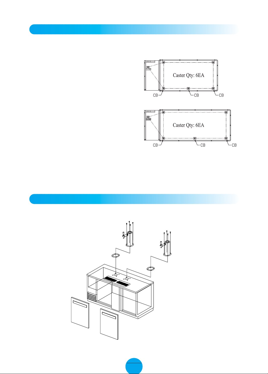
INSTALLA TION OF THE CASTERS
Screw(M4xL12) x 4EA
Screw(M4xL12) x 4EA
Draft T ower Assembly
Draft T ower Assembly
Rubber Gasket
Rubber Gasket
According to model, refer to the assembly position of casters.
TCB-2SD, TBD-2SD, TBB-2SB, TBB-2SG
TCB-3SD, TBD-3SD, TBB-3SB, TBB-3SG
TCB-4SD, TBD-4SD, TBB-4SB, TBB-4SG
picture is a plan view of bottom cabinets.
※ This
CB is an abbreviation of the caster with a brake.
Other casters don't have a brake.
DRAFT ARMS TOWERS Installation Schematic Diagram
* Assemble DRAFT TOWER as above drawing.
TCB-2SD, TCB-3SD, TCB-4SD
TBD-2SD, TBD-3SD, TBD-4SD
TBD-2SB, TBD-3SB, TBD-4SB
3
Turbo air
Page 4
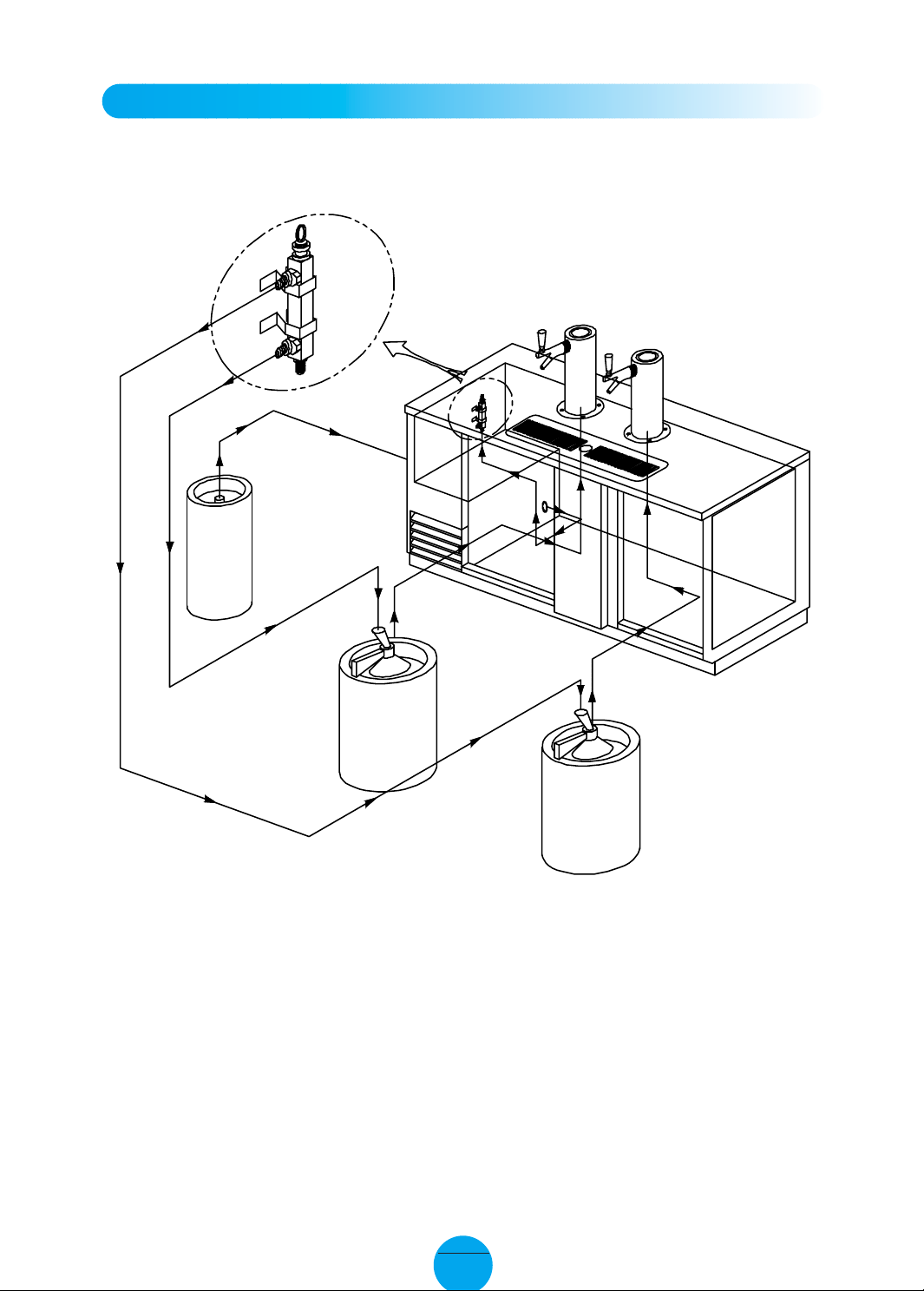
BEER LINE & CO2LINE Installation Schematic Diagram
Distributor Fixture
CO
2 Line
Beer Line#1
Beer Line#2
Beer #1
Beer #2
CO
2
TCB-2SD, TCB-3SD, TCB-4SD
TBD-2SD, TBD-3SD, TBD-4SD
* Assemble BEER LINE & CO2 LINE as above drawing.
TBD-2SB, TBD-3SB, TBD-4SB
4
Turbo air
Page 5

CA UTION "IMPORTANT"
* Don't pull out or Turn drain line.
DIRECT DRAW
On direct-draw dispensers the drain is
located at the front of the cabinet.
To plumb in the drain, connect 5/8”
P.V.C. pipe to the 5/8” barbed fitting
supplies with the unit.
5
Turbo air
Page 6

CA UTION "IMPORTANT"
TBB-2SG, TBB-3SG,
TBB-4SG
A. Excessively opening the door will cause the breakdown.
B. Handle with care as shutting the door.
1. POWER CORD
- Be sure the power cord is connected to the proper voltage, and amps
should be run before connecting power cord to outlet.
- A protected circuit of the correct voltage and amperage must be run for
connection of the line cord.
- Unplug the unit, whenever performing maintenance functions or cleaning
the refrigerated cabinet.
- Compressor warranty is void if burnt out due to low voltage.
2. RE-STARTING
- If unpluged, wait 5 minutes before re-starting.
6
Turbo air
Page 7

INSTALLA TION
1. GOOD AIR CIRCULATION
- Do not place any object that will restrict air flow in front or back grills.
- Turbo air highly recommends that there is ample space in rear of unit. 3 inches or
more is best.
2. PLACE ON STRONG GR OUND
- Be sure the location chosen has a floor strong enough to support the total weight of
the cabinet and contents.
3. DO NOT PLA CE NEAR HEAT
- Be sure to avoid hot corners and locations near stoves.
- High ambient temperature will make cooling efficiency lower.
4. INDOOR USAGE ONLY
- Be sure to install this unit indoor, so it will not get wet from the rain.
5. STABILIZING
- Make sure the unit is installed in a stable condition.
6. LEVELING
- Be sure that the unit is level from front to back and side to side.
7. Do not plug in with other units on same breaker.
8. Do not run on extension cord.
7
Turbo air
Page 8

CLEANING
Before cleaning, unplug the unit.
1. CLEANING THE INTERIOR AND EXTERIOR
- The interior and exterior of the unit can be cleaned using warm water with soap.
- Do not use an abrasive cleaner because it will scratch the surface.
2. CLEANING THE CONDENSER FINS
- To maintain proper refrigeration performance, the Condenser coil must be free of
dust, dirt, and grease.
This will require periodic cleaning. Condenser fins should be cleaned at least every
three months (90 days) or as needed.
- To clean condenser, unplug the unit. Condenser can be cleaned with vacuum, brush,
or CO
3. CLEAN THE GASKET
- The door gasket should be cleaned frequently to maintain proper sealing.
4. CLEAN THE DRAIN PAN
(high pressure air).
2
- Empty the Drain Pan which is located under the unit, periodically.
- When reinstalling Drain Pan, make sure Drain Hose is placed back in pan.
5. CHECK AFTER CLEANING
- Plug unit back in.
- Check that the unit is operating properly.
8
Turbo air
Page 9

BASIC OPERATION
REFRIGERATORS
1. The controller(thermostat) is located at the back right inside of the unit.
2. The factory setting maintains about 38˚F(3˚C) inside.
3. Set toward “counter clock wise” warmer temperature and “clock wise” for colder
temperature.
Temperature Controller
(Thermostat)
4. The thermostat controls compressor’s cycling by sensing inside temperature.
5. When unit will not be used for a long time, unplug the unit.
9
Turbo air
Page 10

BEFORE REQUESTING SER VICE
SYMPTOMS CAUSES SOLUTIONS
Cooler is freezing
products
The unit does not
refrigerate at all.
The unit does not
refrigerate well.
There is a loud noise.
There are dew-drops
on the unit exterior .
• Thermostat set too cold.
• There is a power connection
failure problem.
• The unit is in sunlight or near a
heating device.
• Product was put in warm.
• The unit door is opened too
frequently or left open too long.
• The temp. dial is not on the
correct position.
• The condenser is clogged.
• The floor is too weak or the
leveling feet are set incorrectly.
• The backside of the unit is too
close to the wall.
• High-moisture air can produce
dewdrops during rainy seasons.
• Turn the temperature dial to a
warmer setting.
• Check the power cord to make
sure the unit is pluged in it
correctly.
• Move out of sunlight or away
from heater.
• Check the condition of stored
food.
• Check the position of the temp
control dial.
• Check the installation.
• Wipe with a dry cloth.
There are dew-drops
on the unit interior.
• The door is opened too
frequently or left open too long.
• Keep the door closed to
remove dewdrops.
The following points are not malfunctions:
• A water-flowing sound can be heard when the compressor stops.
This is the sound of REFRIGERANT flowing.
• The compressor does not run during the defrost cycle.
10
Turbo air
Page 11

Warranty
Warranty Claims
All claims for labor or parts must be made directly through Turbo Air. If unit was manufactured more than one year,
proof of purchase must be faxed in or sent with claim. All claims should include: model number of the unit, the serial
number of the cabinet, and all pertinent information supporting the existence of the alleged defect.
If compressor is replaced under warranty, Turbo Air will either request the compressor or compressor tag be returned.
Compressor or tag must be returned with all information related to the unit. Any action or breach of these warranty
provisions must be commenced within one year after said cause of action has occurred.
One Y ear Parts & Labor W arranty
Turbo Air warrants to the original purchaser of every new Turbo Air refrigerated unit, the cabinet and all parts thereof,
to be free from defects in material or workmanship, under normal and proper use and maintenance service as
specified by Turbo Air and upon proper installation and start-up in accordance with the instruction packet supplied
with each Turbo Air unit. Turbo Air’s obligation under this warranty is limited to a period of one (1) year from the date
of original installation or 15 months after shipment date from Turbo Air, whichever occurs first.
Any parts, covered under this warranty, that are determined by Turbo Air to have been defective within one (1) year
of original installation or fifteen (15) months after shipment date from manufacturer, whichever occurs first, is limited to
the repair or replacement, including labor charges, of defective parts or assemblies. The labor warranty shall include
standard straight time labor charges only and reasonable travel time, as determined by Turbo Air.
Additional Four Year Compressor Warranty
In addition to the one (1) year warranty stated above, Turbo Air warrants its hermetically sealed compressor to be free
from defects in both material and workmanship under normal and proper use and maintenance service for a period of
four (4) additional years from the date of original installation, but not to exceed five (5) years and three (3) months
after shipment from the manufacturer.
Compressor determined by Turbo Air to have been defective within this extended period will, at Turbo Air’s option, be
either repaired or replaced with a compressor or compressor parts of similar design and capacity.
The four (4) year extended compressor warranty applies only to hermetically sealed parts of the compressor and
does not apply to any other parts or components, including, but not limited to, cabinet, paint finish, temperature
control, refrigerant, metering device, driers, motor starting equipment, fan assembly or and other electrical
component, etcetera.
404A / 134A Compressor Warranty
The four-year compressor warranty detailed above will be voided if the following procedure is not carefully adhered to:
1. This system contains R404A or R134A refrigerant and polyolester lubricant. The polyol ester lubricant has
rapid moisture absorbing qualities.
2. Drier replacement is very important and must be changed when a system is opened for servicing. A 620
copper drier or better is highly recommended.
3. Micron level vacuums must be achieved to insure low moisture levels in the system. 500 microns or lower
must be obtained.
4. When compressor is grounded, suction filter drier and 620 drier or better must be replaced.
5. Compressor must be obtained through Turbo Air Inc., unless otherwise specified in writing, through Turbo
Air’s warranty department.
11
Turbo air
Page 12

What Is Not Covered By This W arranty
Turbo Air’s sole obligation under this warranty is limited to either repair or replacement of parts, subject to the
additional limitations below. This warranty neither assumes nor authorizes any person to assume obligations other
than those expressly covered by this warranty.
NO CONSEQUENTIAL DAMAGES. TURBO AIR IS NOT RESPONSIBLE FOR ECONOMIC LOSS; PROFIT
LOSS; OR SPECIAL, INDIRECT, OR CONSEQUENTIAL DAMAGES, INCLUDING WITHOUT LIMITATION,
LOSSES, OR DAMAGES ARISING FROM FOOD OR PRODUCT SPOILAGE CLAIMS WHETHER OR NOT
BECAUSE of REFRIGERATION FAILURE.
WARRANTY IS NOT TRANSFERABLE. This warranty is not assignable and applies only in favor of the original
purchaser / user to whom delivered. ANY SUCH ASSIGNMENT OR TRANSFER SHALL VOID THE WARRANTIES
HEREIN MADE AND SHALL VOID ALL WARRANTIES, EXPRESS OR IMPLIED, INCLUDING ANY WARRANTY
OF MERCHANTABILITY OR FITNESS FOR A PARTICULAR PURPOSE.
IMPROPER USAGE. TURBO AIR ASSUMES NO LIABILITY FOR PARTS OR LABOR COVERAGE FOR
COMPONENT FAILURE OR OTHER DAMAGES RESULTING FROM IMPROPER USAGE OR INSTALLATION
OR FAILURE TO CLEAN AND / OR MAINTAIN PRODUCT AS SET FORTH IN THE WARRANTY PACKET
PROVIDED WITH THE UNIT.
ALTERATION, NEGLECT, ABUSE, MISUSE, ACCIDENT, DAMAGE DURING TRANSIT OR INSTALLATION,
FIRE, FLOOD, ACTS OF GOD. Turbo Air is not responsible for the repair or replacement of any parts that Turbo Air
determines have been subjected after the date of manufacture to alteration, neglect, abuse, misuse, accident,
damage during transit or installation, fire, flood, or act of God.
IMPROPER ELECTRICAL CONNECTIONS. TURBO AIR IS NOT RESPONSIBLE FOR THE REPAIR OR
REPLACEMENT OF FAILED OR DAMAGED COMPONENTS RESULTING FROM ELECTRICAL POWER
FAILURE, THE USE OF EXTENSION CORDS, LOW VOLTAGE, OR VOLTAGE DROPS TO THE UNIT.
NO IMPLIED WARRANTY OF MERCHANTABILITY OR FITNESS FOR A PARTICULAR PURPOSE: THERE
ARE NO OTHER WARRANTIES, EXPRESSED, IMPLIED OR STATUTORY, EXCEPT THE ONE (1) YEAR
PARTS & LABOR WARRANTY AND THE ADDITIONAL FOUR (4) YEAR COMPRESSOR WARRANTY AS
DESCRIBED ABOVE. THESE WARRANTIES ARE EXCLUSIVE AND IN LIEU OF ALL OTHER WARRANTIES,
INCLUDING IMPLIED WARRANTY AND MERCHANTABILITY OR FITNESS FOR A PARTICULAR PURPOSE.
THERE ARE NO WARRANTIES, WHICH EXTEND BEYOND THE DESCRIPTION ON THE FACE HEREOF.
OUTSIDE U.S. AND CANADA: This warranty does not apply to, and Turbo Air is not responsible for, any warranty
claims made on products sold or used outside the United State and Canada.
CHANGES MADE TO WARRANTY COMMENCED ON 5/1/2002
12
Turbo air
Page 13

13
Turbo air
1250 Victoria street
CARSON, CA 90746
TEL: 310-900-1000
FAX: 310-900-1077
Toll Free: 1-800-627-0032
(U.S.A. In Canada)
http://www.turboairinc.com
 Loading...