

Page 1

REFRIGERATOR MANUFACTURER
TBC
95SD/SB
Turbo air
Commercial
Refrigerator
Service Manual
Horizontal Bottle Coolers
Model No. : TBC-24SD/SB
TBC-36SD/SB
TBC-50SD/SB
TBC-65SD/SB
TBC-80SD/SB
-
Page 2

TABLE OF CONTENTS
1. FEATURE CHART
2. WIRING DIAGRAM
3. PART DETAILS
4. MAIN COMPONENTS
5. TEMPERATURE CONTROL INSTRUCTION
6. PARTS LIST
7. REPLACEMENT OF MAIN COMPONENTS
Page 3
1. FEATURE CHART
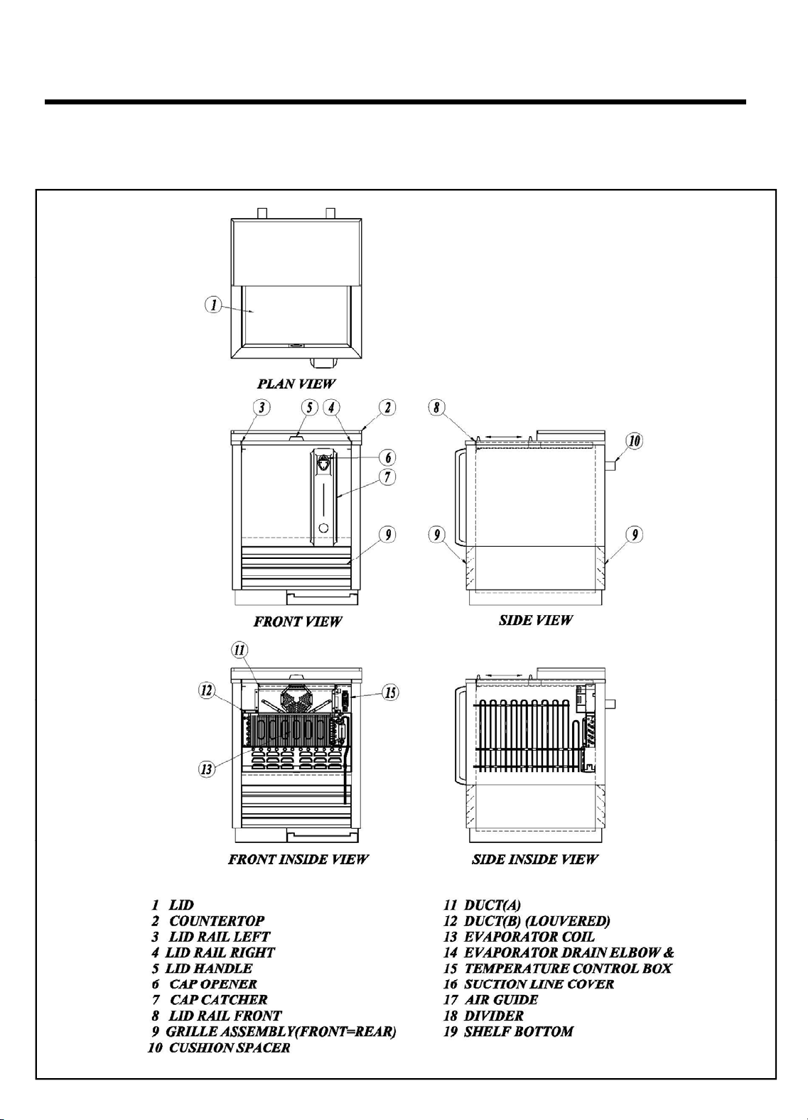
1-1. TBC-24SD/SB
Page 4
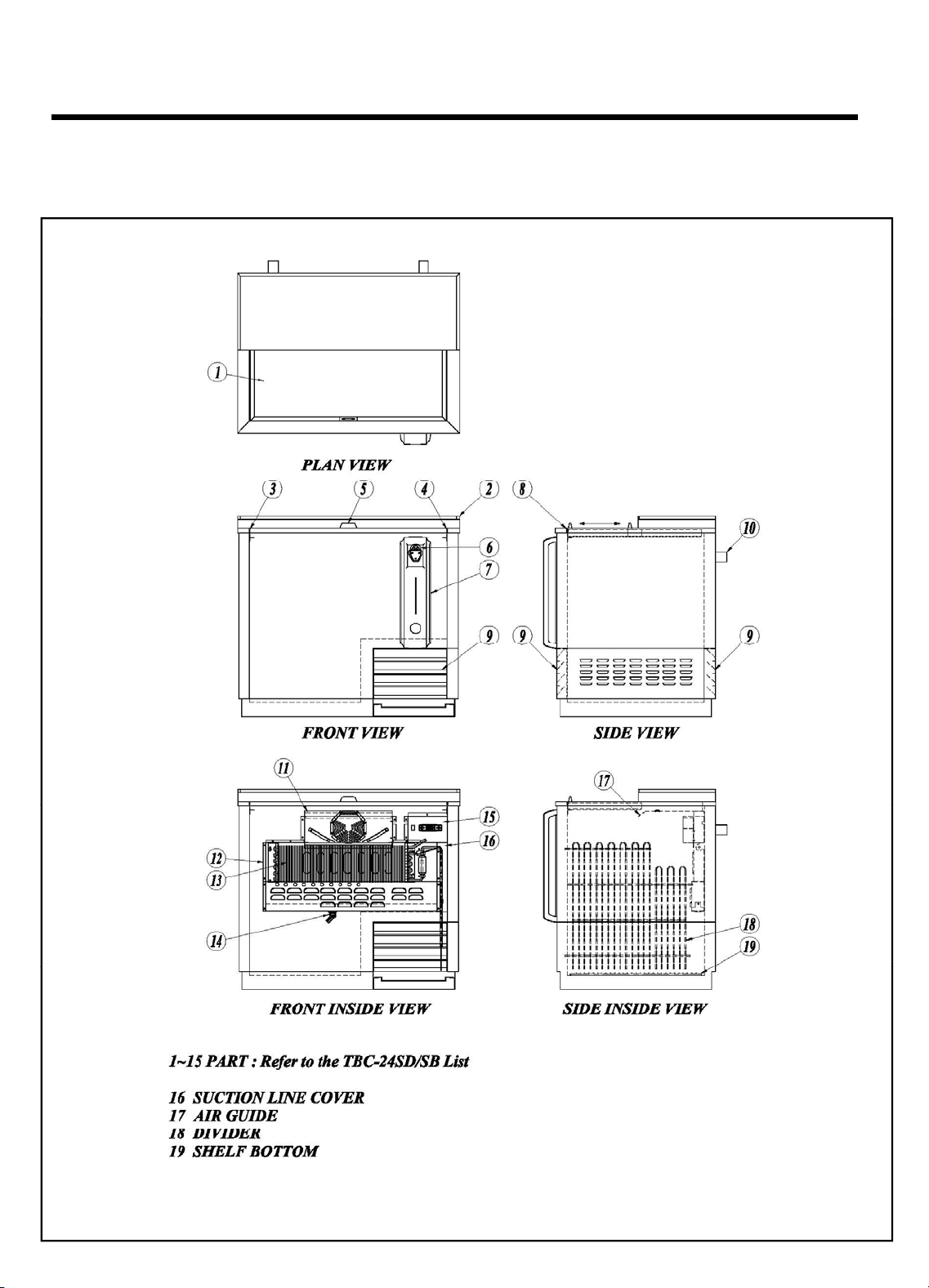
1-2. TBC-36SD/SB
FEATURE CHART
Page 5
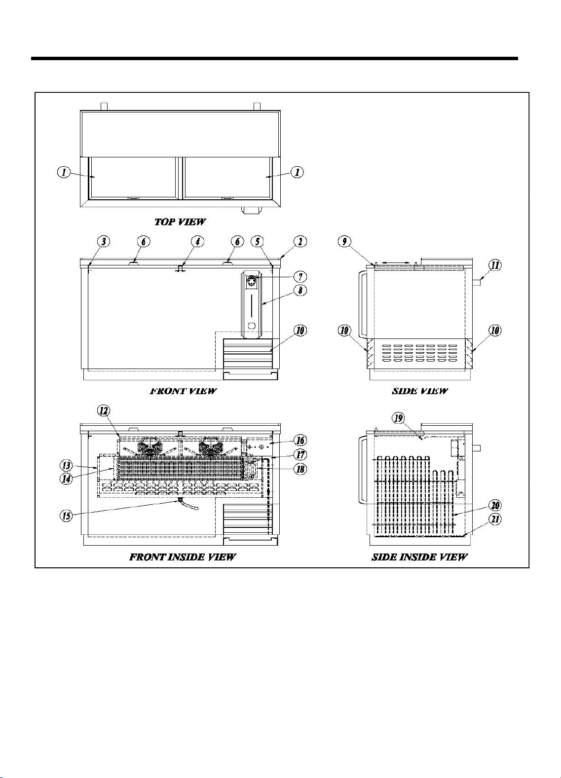
1-3. TBC-50SD/SB, TBC-65SD/SB
1.LID
11.CUSHION SPACER
8.CAP CATCHER
18.LEAK TEST COVER
FEATURE CHART
2. COUNTER TOP
3. LID RAIL LEFT
4. LID RAIL MIDDLE
5. LID RAIL RIGHT
6. LID HANDLE
7. CAP OPENER
9. LID RAIL FRONT
10. GILLE ASSEMBLEY(FRONT = REAR)
12. DUCT(A)
13. DUCT(B) (LOUVERED)
14. EVAPORATOR COIL
15. EVAPORATOR DRAIN ELBOW & HOSE
16. TEMPERATURE CONTROL BOX
17. SUCTION LINE COVER
19. AIR GUIDE
20. DIVIDER
21. SHELF BOTTOM
Page 6
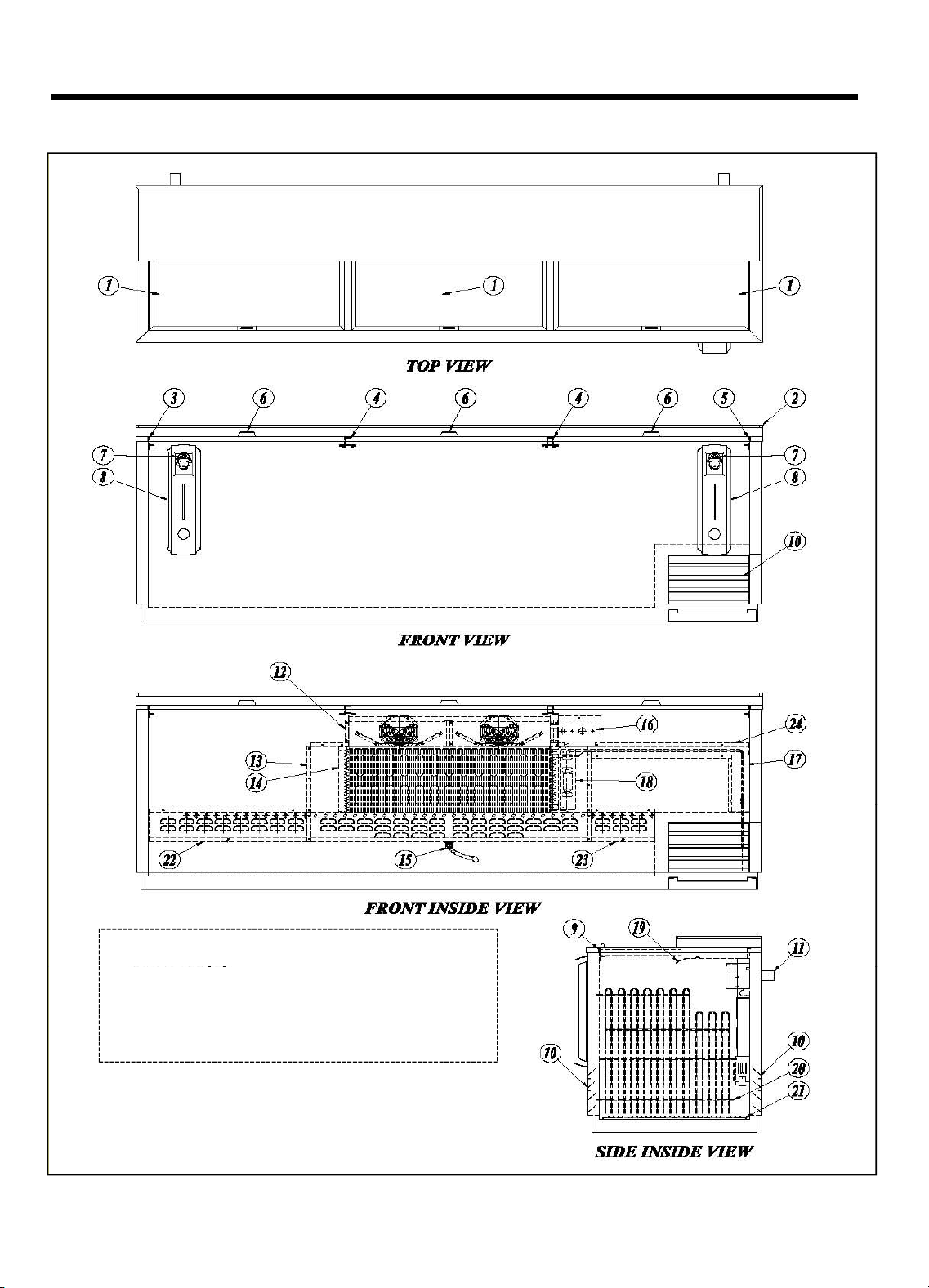
1-4. TBC-80SD/SB, TBC-95SD/SB
FEATURE CHART
1~21 PART : Refer to the TBC-50SD/SB LIST
22. DUCT(C)
23. DUCT(D)
24. SUCTION LINE COVER(HORIZONTAL)
Page 7
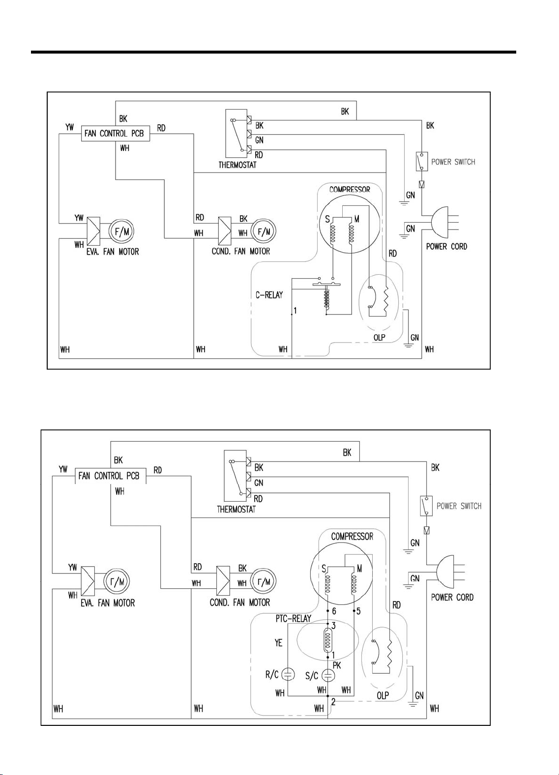
2. WIRING DIAGRAM
2-1. TBC-24SD/SB
2-2. TBC-36SD/SB
Page 8
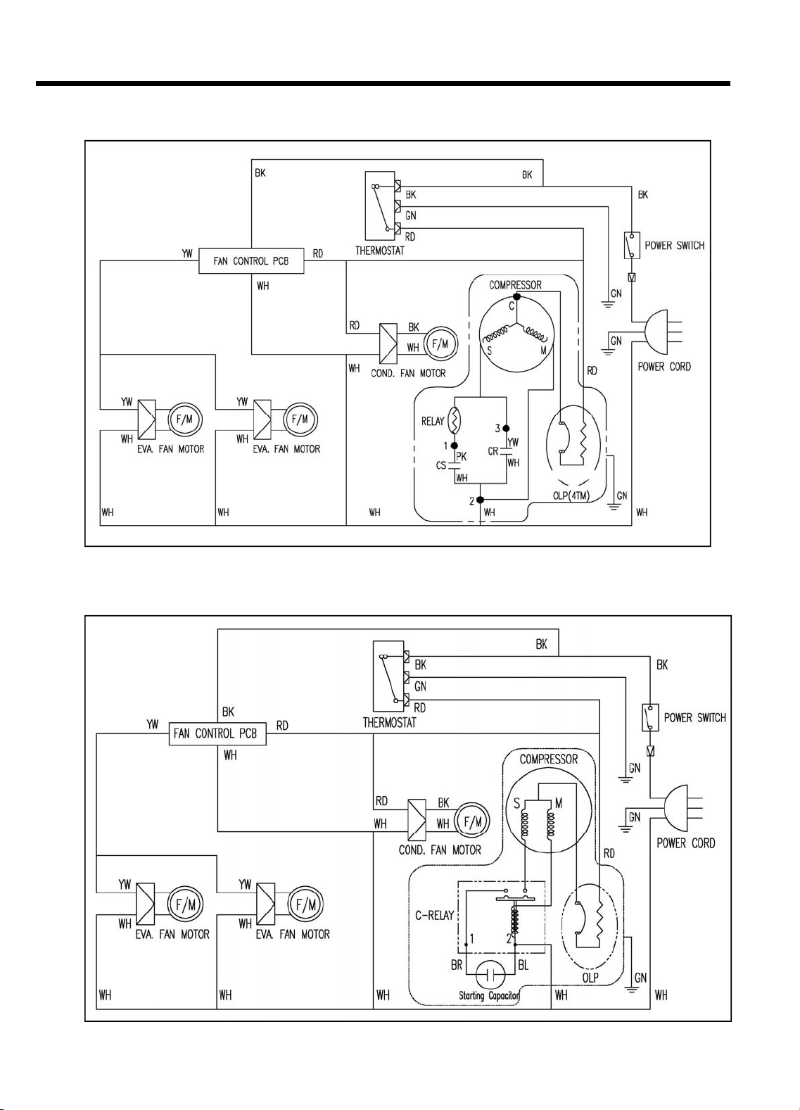
WIRING DIAGRAM
2-3. TBC-50SD/SB, TBC-65SD/SB
2-4. TBC-80SD/SB, TBC-95SD/SB
Page 9

3. PART DETAILS
3-1. EVAPORATOR FAN MOTOR
Motor B
t
TBC
50SD/SB
3-2. CONDENSER FAN MOTOR
Evaporator Fan Blade
Motor Bracket
Evaporator Fan Motor
Condenser Fan Blade
Motor Bracket
Condenser Fan Motor
TBC-24SD/SB
TBC-36SD/SB
racke
Condenser Fan Motor
Condenser Fan Blade
TBC-65SD/SB
TBC-80SD/SB
TBC-95SD/SB
Page 10

PART DETAILS
3-3. DUCT(A) : EVAPORATOR FAN MOTOR DUCT
3-4. DUCT(B),(C),(D)
DUCT(C)
DUCT(B) DUCT(D)
Page 11

PART DETAILS
3-5. EVAPORATOR COIL
[ TBC-50SD/SB, TBC-65SD/SB ]
[ TBC-80SD/SB, TBC-95SD/SB ]
SENSOR INLET
ACCUMULATOR
Page 12

PART DETAILS
3
6. CONDENSER COIL
-
[ TBC-50SD/SB, TBC-65SD/SB ] [ TBC-80SD/SB, TBC-95SD/SB ]
Page 13

PART DETAILS
3-7. DIVIDER
[ TBC-24SD/SB]
[ TBC-36SD/SB, TBC-50SD/SB, TBC-65SD/SB ]
3-8. DIVIDER SPRING
[ TBC-80SD/SB, TBC-95SD/SB ]
Page 14

PART DETAILS
AC input
3-9. COUNTER TOP
3-10. Fan Control PCB
Fan output
Compressor
on/off signal
Page 15

4. MAIN COMPONENTS
1. COMPRESSOR
896 BTU/h
LBP
C-95SD/S
C
95S /S
TBC-95SD/SB
TBC-80SD/SB
MODEL PART NAME PART NO.
TBC-24SD/SB HFL11Y-1 30289A0400 1/10 HP
TBC-36SD/SB HBL27YE-1 3952127G10 1/4 HP
TBC-50SD/SB
TBC-65SD/SB
TBC-80SD/SB
TB
B
SK1A1C-L2W 30200Q1200 1/3 HP
CAE4456Y 30200B4500 1/2 HP
HORSE
POWER MOTOR (RLA)
CAPACITY
373 BTU/h LBP
(94 Kcal/h) RSIR
(226 Kcal/h) CSR
1,202 BTU/h LBP
(303 Kcal/h) CSR
5,592BTU/h HBP
(1,410 Kcal/h)
TYPE OF Current
1.9A DAEWOO
3.7A DAEWOO
4.0A SAMSUNG
CSIR
9.0A TECUMSEH
2. COMPRESSOR RELAY, OVERLOAD
MODEL RELAY OVERLOAD PROTECTOR MAKER
TBC-24SD/SB S068 (PTC-RSIR) 4TM-293THBYY-52 DAEWOO
TBC-36SD/SB S068 (PTC-CSR) 4TM 783SHBZZ-52 DAEWOO
MAKER
TBC-50SD/SB
J531Q34E22OM3503 4TM 795TFBZZ-53 SAMSUNG
TBC-65SD/SB
TBC-80SD/SB
KPF498***** T0889 TECUMSEH
3. COMPRESSOR CAPACITOR
MODEL STARTING PART NO. RUNNING PART NO.
TBC-24SD/SB - - - TBC-36SD/SB 220V/100
TBC-50SD/SB
125V / 125
TBC-65SD/SB
160V / 315
TBC-95SD/SB
㎌
㎌
㎌
3017906900 230V/10
- 250V / 12
---
㎌
㎌
381791600
-
Page 16

MAIN COMPONENTS
4. EVAPORATOR FAN MOTOR
▶
THERMOSTAT ON/OFF SPEC
MODEL PART NAME PART NO. POLE BLADE SIZE MAKER
ALL DAI-6202DEUA 3963339930 2P ZITEL 110mm DAE-YOUNG
5. CONDENSER FAN MOTOR
MODEL PART NAME PART NO. POLE BLADE SIZE MAKER
TBD-1SD
IS-3225DWSQ-2 3963326710 2P ZITEL 150mm SUNG-SHIN
TBB-1SB
TBC-50SD/SB
TBC-65SD/SB
TBC-80SD/SB
TBC-95SD/SB
6. THEMOSTAT
MODEL PART NAME PART NO. MAKER
ALL GNA-242L 30283F1000 SHIN-HAN
MODEL
GNA-242L 8.0 -5.0 5.0 -9.0 2.8 -12.5
IS-4420DWSG-1 3963320410 4P Aluminum 200mm SUNG-SHIN
.
WARM NORMAL COLD
On Off On Off On Off
7. FAN-CONTROL PCB
MODEL PART NAME PART NO. MAKER
ALL FAN CONTROL PCB P0143A0100 NEUROSYS
Page 17

5. TEMPERATUR CONTROL INSTRUCTION
▶
Compressor is automatically turned on and off by thermostat.
5-1. HOW TO USE THE TEMPERATURE CONTROL
▶ Temperature can be controlled by the user.
▶ Settings can be changed by “Dial Knob”.
TEMPERATURE CONTROL
5-2. FAN CONTROL PCB
▶ Cooling Fan Motors are controlled by “Fan Control PCB”
▶ Cooling Fan Motors are continuously operating while compressor is operating
▶ It is repeated during compressor is not operaing that Cooling Fan Motors are
not operating 3 minutes and operating 1 minutes.
Page 18

6. PARTS LIST
Page 19

PARTS LIST
Page 20

7. REPLACEMENT OF MAIN COMPONENTS
▶
CAUTION : Unpl
ug the unit before replacing any part.
7-1. REPLACING DOOR THE EVAPORATOR COIL
A. Remove all lids. Remove the dividers.
(Now, you can replace the evaporator fan motor or the temperature control(thermostat) if you
unscrew the duct(A) or the temperature control box.)
B. Cut the silicone line around the countertop frame with a knife.
Remove all screws in back of the countertop frame.
C. Remove all the screws around the lid rail.
Lift the countertop from the rear first. Push countertop forward and top will come off.
Page 21

REPLACEMENT OF MAIN COMPONENTS
D. Carefully move the countertop to a safe place.
See the join bracket and understand join system.
E. This is the duct(A) and the temperature control box.
Unscrew the temperature control box if necessary.
E. Unplug the temperature control harness assembl y.
Page 22

REPLACEMENT OF MAIN COMPONENTS
G. Pull the sensing tube of the temperature control.
Replace the temperature control if necessary.
H. Remove the screws on duct(A) and Remove.
I. Unplug the evaporator fan motor harness assembly if necessary.
Page 23

REPLACEMENT OF MAIN COMPONENTS
J. Remove screws to the evaporator fan motor if necessary and replace it with new one.
K. Remove the screws on duct(B) and Remove.
L. Remove the screws on the suction line cover(horizontal) if necessary.
Page 24

REPLACEMENT OF MAIN COMPONENTS
() () y
M. Remove screws to the duct(C) and the duct(D) if necessary.
N. Now evaporator coil is visible.
To replace it, cut out at the welding point between the accumulator and the suction line,
and also of the end of the capillary tube.
Page 25

REPLACEMENT OF MAIN COMPONENTS
() () y
In pushing the compressor compartment to the original position, please be careful so the
O. Remove screws to the duct(C) and the duct(D) if necessary.
7-2. ACCESSING CONDENSER COMPARTMENT
A. After removing the front grille assembly, unscrew the compressor base.
Pull the compressor compartment slowly.
Compressor, Condenser coil, Condenser fan motor, etc. can be replaced.
•
capillary tube does not bend.
 Loading...