

Page 1
CAUTION!
PLEASE KEEP POWER
SWITCH ON BEFORE
OPERATING THIS EQUIPMENT
Turbo Air Speed up the Pace of Innovation
Display Cases
Bakery Cases
Service Manual
Please read this manual completely before attempting to install or operate this equipment!
TB-4 TB-4R
TB-5 TB-5R
www.turboairinc.com
Page 2

TABLE OF CONTENTS
1. FEATURE CHART
1-1. FRONT VIEW
1-2. SIDE VIEW
1-3. REAR VIEW
2. WIRING DIAGRAM
2-1. REFRIGERATOR (A PART OF PRODUCT BEFORE APR 2005)
2-2. REFRIGERATOR (APPLY FROM TB5R004001, TB4R004001)
2-3. REFRIGERATOR (REMOVE THE CONDENSER REMOVE)
2-4. DRY CASE
3. PART DETAILS
3-1. SIDE GLASS PART
3-2. FRONT GLASS PART
3-3. WIRE SHELF LATHE PART
3-4. LAMP ASSY
3-5. FRONT MOTOR PART
3-6. FRONT GASKET PART
3-7. REFRIGERATION COMPARTMENT
3-8. COOLING COMPARTMENT
3-9. CONTROL BACK
3-10. WIRING BACK
3-11. BACK DOOR
4. MAIN COMPONENTS
4-1. COMPRESSOR
4-2. LIQUID LINE FILTER
4-3. EXPANSION VALVE
4-4. EVAP & COND FAN MOTOR
4-5. CONDENSER FAN BLADE
4-6. EVAP FAN BLADE
4-7. POWER SWITCH
4-8. CONDENSER REMOVE
4-9. BALLAST F LAMP
4-10. FLUORESCENT LAMP
4-11. LAMP SOCKET
4-12. MAIN PCB
4-13. DISPLAY PCB
4-14. TRANS FORMER
4-15. GAS SPRING
4-16. SERVICE VALVE
5. ELECTRONIC CONTROL INSTRUCTIONS
5-1. REFRIGERATOR CONTROL
5-1-1. HOW TO USE THE DISPLAY PCB PANEL
5-1-2. ERROR CODE
5-1-3. FUNCTION TABLE
Page 3

6. TROUBLE SHOOTING CHART
6-1. THE REFRIGERATOR DOES NOT COOLING
6-2. THE REFRIGERATOR DOES NOT COOLING WELL
7. REFRIGERANT CYCLE DIAGRAM
8. REPLACEMENT OF MAIN COMPONENTS
8-1. END CLASS PART
8-2. FRONT GLASS PART
8-3. LATHE TOP COVER PART
8-4. WIRE SHELF LATHE PART
8-5. FRONT MOTOR PART
8-6. FRONT GLASS PART
8-7. REFRIGERATION COMPARTMENT
8-8. COOL COMPARTMENT
8-9. CONTROL BACK PART
8-10. MAIN WIRING PART
9. PART LIST
Page 4
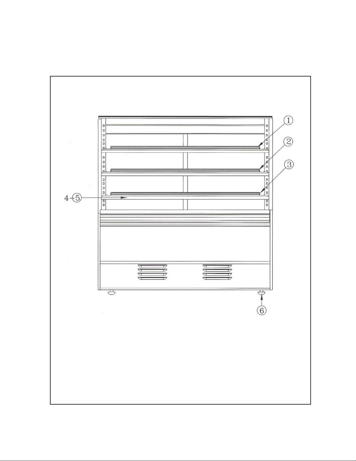
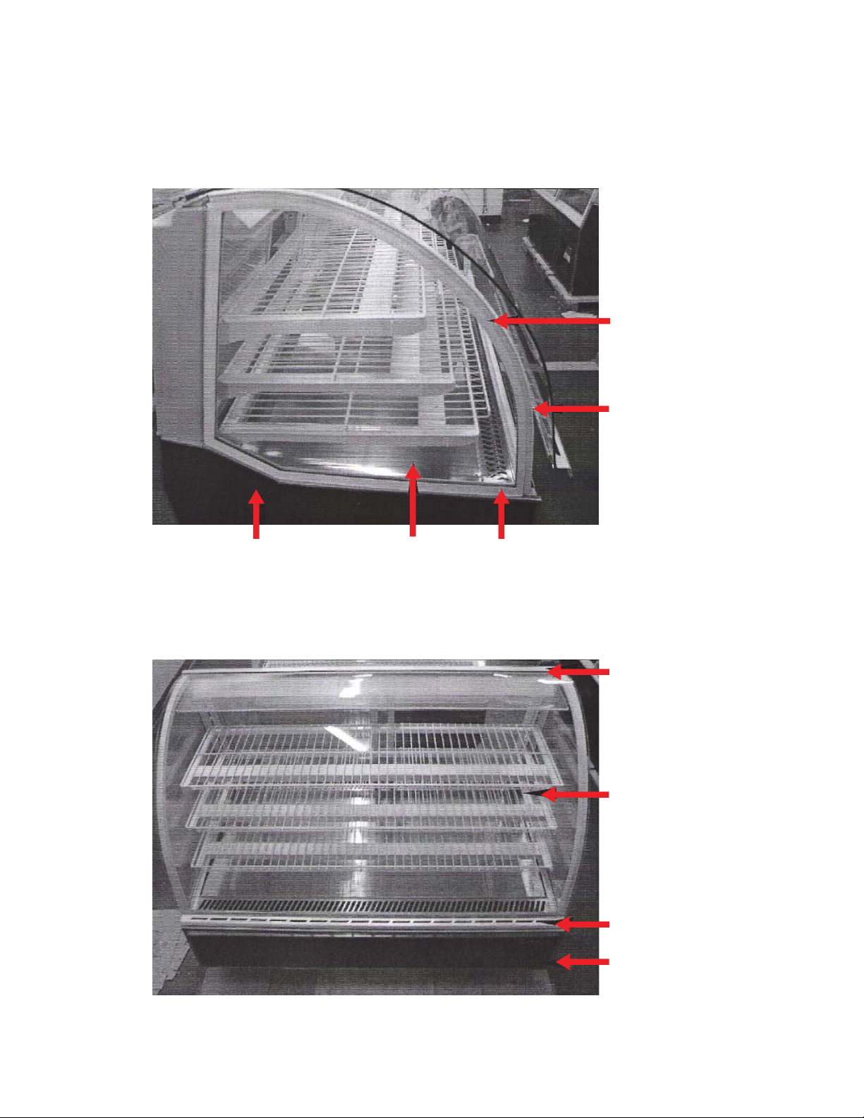
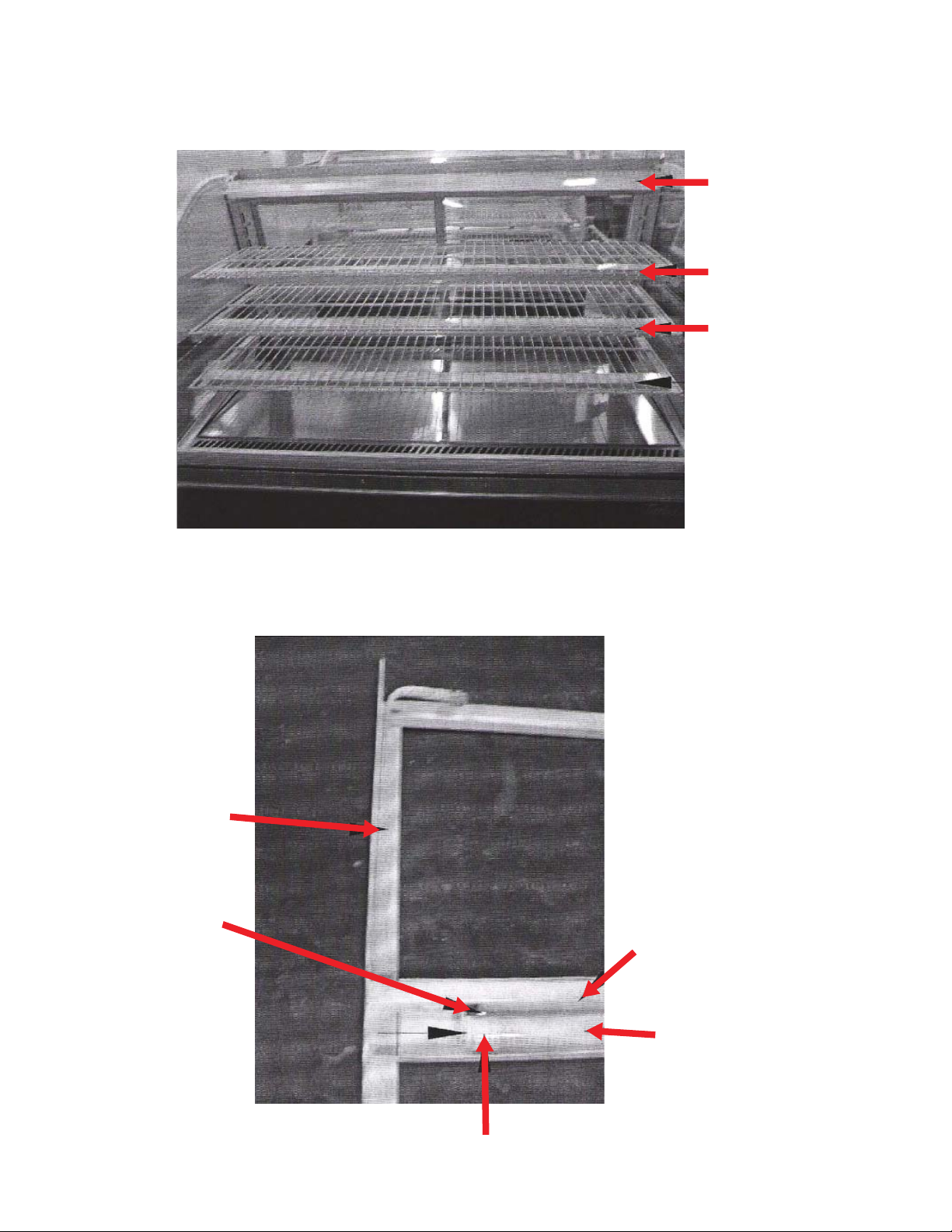
1. FEATURE CHART
1-1. FRONT VIEW
1. WIRE SHELF TOP ASSY (LAMP INSIDE)
2. WIRE SHELF MIDDLE ASSY (LAMP INSIDE)
3. WIRE SHELF LOWER ASSY (LAMP INSIDE)
4. FLUORESCENT TUBE
5. FLUORESCENT LAMP
6. LEG BOLT
Page 5
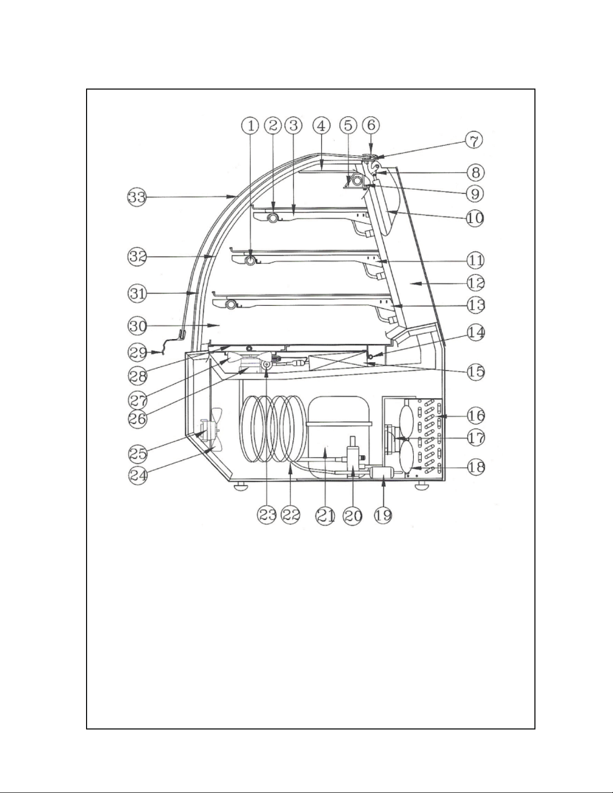
1-2. SIDE VIEW
1. LAMP SOCKET
2. LAMP SOCKET COVER
3. WIRE SHELF LAT SHOT ASSY
4. ARCYLE COVER A
5. ARCYLE COVER C
6. TOP GLASS CLAMP A
7. TOP GLASS CLAMP B
8. UNDER GLASS CLAMP
9. LATHE TOP COVER ASSY
10. GAS SPRING
11. WIRE SHELF LAT MID ASSY
12. COVER FRAME L (R)
13. WIRE SHELF LAT LARGE ASSY
14. THERMISTER ASSY
15. EVAP COIL ASSY
16. CONDENSER ASSY
17. COND FAN MOTOR ASSY
18. COND FAN BLADE
19. LIQUID LINE FILTER
20. SVC VALVE
21. COMPRESSOR
22. SUCTION LINE
23. EXPANSION VALVE
24. FRONT FAN BLADE
25. FRONT FAN MOTOR
26. EVAP FAN MOTOR
27. EVAP FAN BLADE
28. DISPLAY PAN
29. GLASS CLAMP
30. END GLASS
31. SIDE GLASS GASKET
32. SIDE GLASS SASH
33. FRONT GLASS
Page 6

1-3. REAR VIEW
1. BACK DOOR FRAME SASH A
2. TOP COVER FRAME
3. BACK DOOR RIGHT ASSY
4. BACK DOOR FRAME SASH B
5. CONTROL AREA
6. POWER SWITCH
7. MAIN PCB ASSY
8. TRANS FORMER
9. DISPLAY PCB
10. UNIT AREA
11. COMP ELECTR BOX
12. BALLAST F LAMP
13. CONDENSER REMOVE
14. DRAIN HOSE
15. WIRE JOINT AREA
16. BACK DOOR LEFT ASSY
Page 7
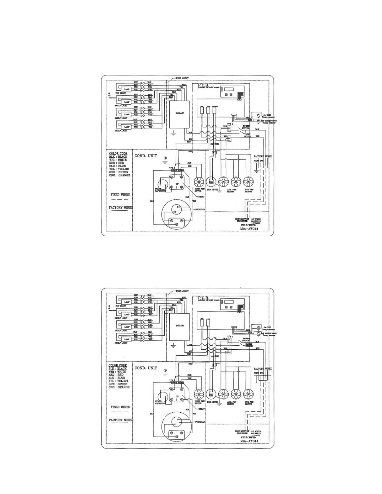
2. WIRING DIAGRAM
2-1. REFRIGERATOR
(A PART OF PRODUCTE BEFORE APR 2005)
COPPER ALUMINUM CONDUCTOR ONLY
2-2. REFRIGERATOR
(APPLY FROM TB5R004001, TB4R004001)
COPPER ALUMINUM CONDUCTOR ONLY
Page 8
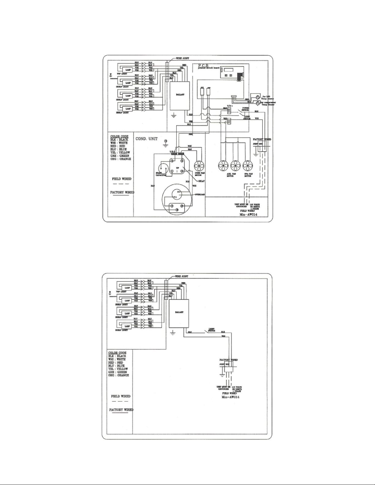
2-3. REFRIGERATOR
(REMOVE THE CONDENSER REMOVE)
2-4. DRY CASE
COPPER ALUMINUM CONDUCTOR ONLY
COPPER ALUMINUM CONDUCTOR ONLY
COPPER ALUMINUM CONDUCTOR ONLY
Page 9
3. PART DETAILS
3-1. SIDE GLASS PART
END GLASS
GASKET SASH
END GLASS
GASKET
SIDE PANEL END GLASS END GLASS SASH
3-2. FRONT GLASS PART
TOP GLASS
CLAMP A(B)
FRONT GLASS
GLASS CLAMP
FRONT PANEL
Page 10
3-3. WIRE SHELF LATHE PART
LATHE TOP
COVER ASSY
WIRE SHELF LATHE
SHOT ASSY
WIRE SHELF LATHE
MID ASSY
WIRE SHELF LATHE
LARGE ASSY
3-4. LAMP ASSY
WIRE SHELF
LATHE PART
(BACK)
LAMP SOCKET
CLAMPER
LAMP SOCKET
COVER
FLUORESCENT
LAMP
LAMP SOCKET
Page 11
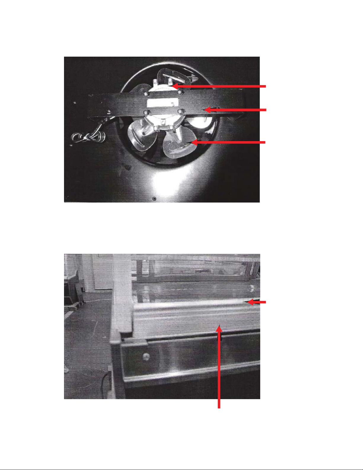
3-5. FRONT MOTOR PART
FAN MOTOR (9W)
MOTOR BRACKET
FAN BLADE (Ø200)
3-6. FRONT GASKET PART
FRONT GASKET
FRONT GASKET SASH
Page 12
COMPRESSOR
SVC VALVE
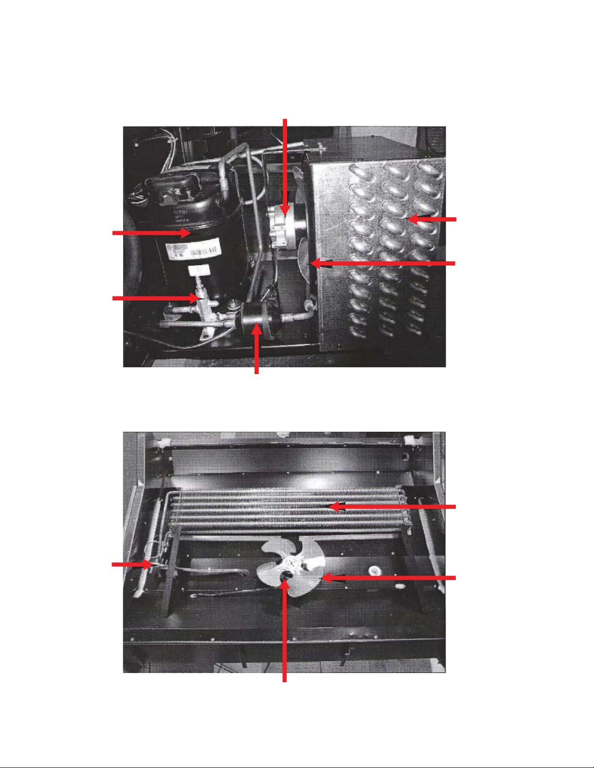
3-7. REFRIGERATION COMPARTMENT
CONDENSING UNIT
FAN MOTOR (9W)
CONDENSER
FAN BLADE (Ø250)
EXPANSION
VALV E
LIQUID LINE FILTER
3-8. COOLING COMPARTMENT
EVAP COIL
FAN BLADE (Ø200)
FAN MOTOR (9W)
Page 13
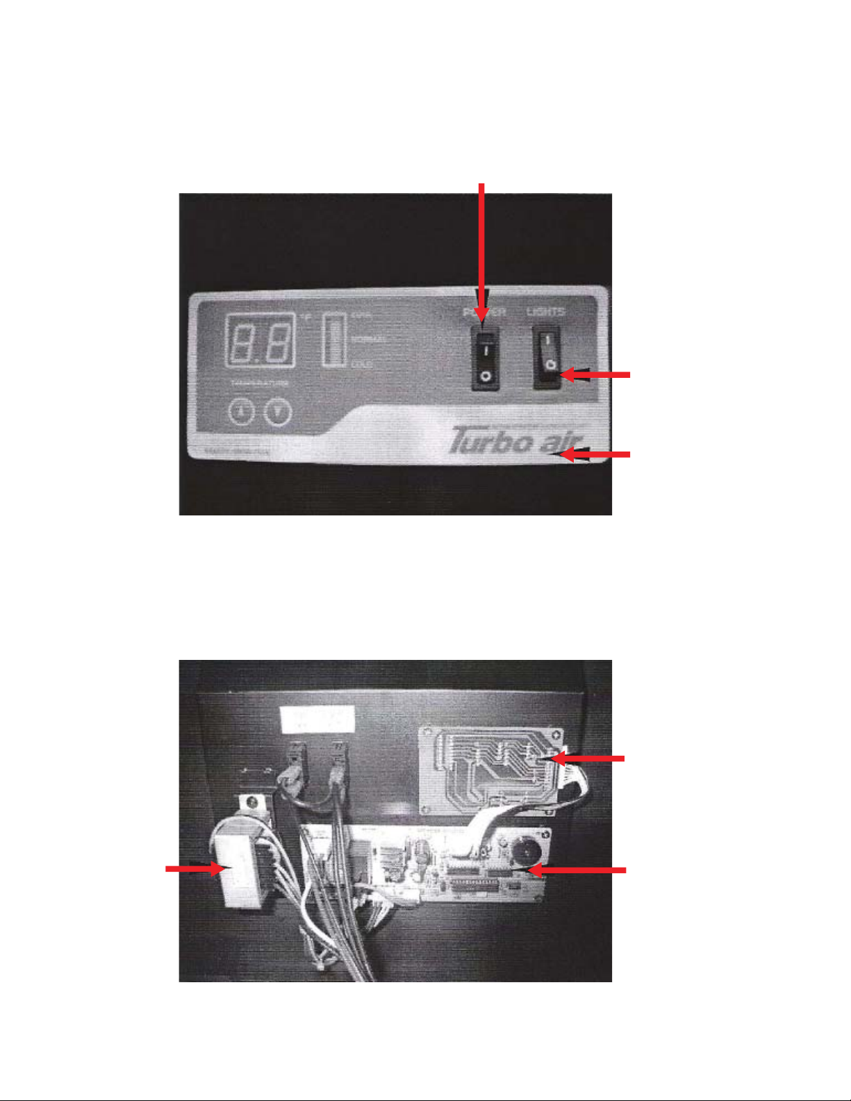
3-9. CONTROL BACK
DISPLAY
POWER SWITCH
LIGHTS SWITCH
INLAY PCB
TRANSFORMER
DISPLAY PCB & MAIN PCB
DISPLAY PCB
MAIN PCB
Page 14
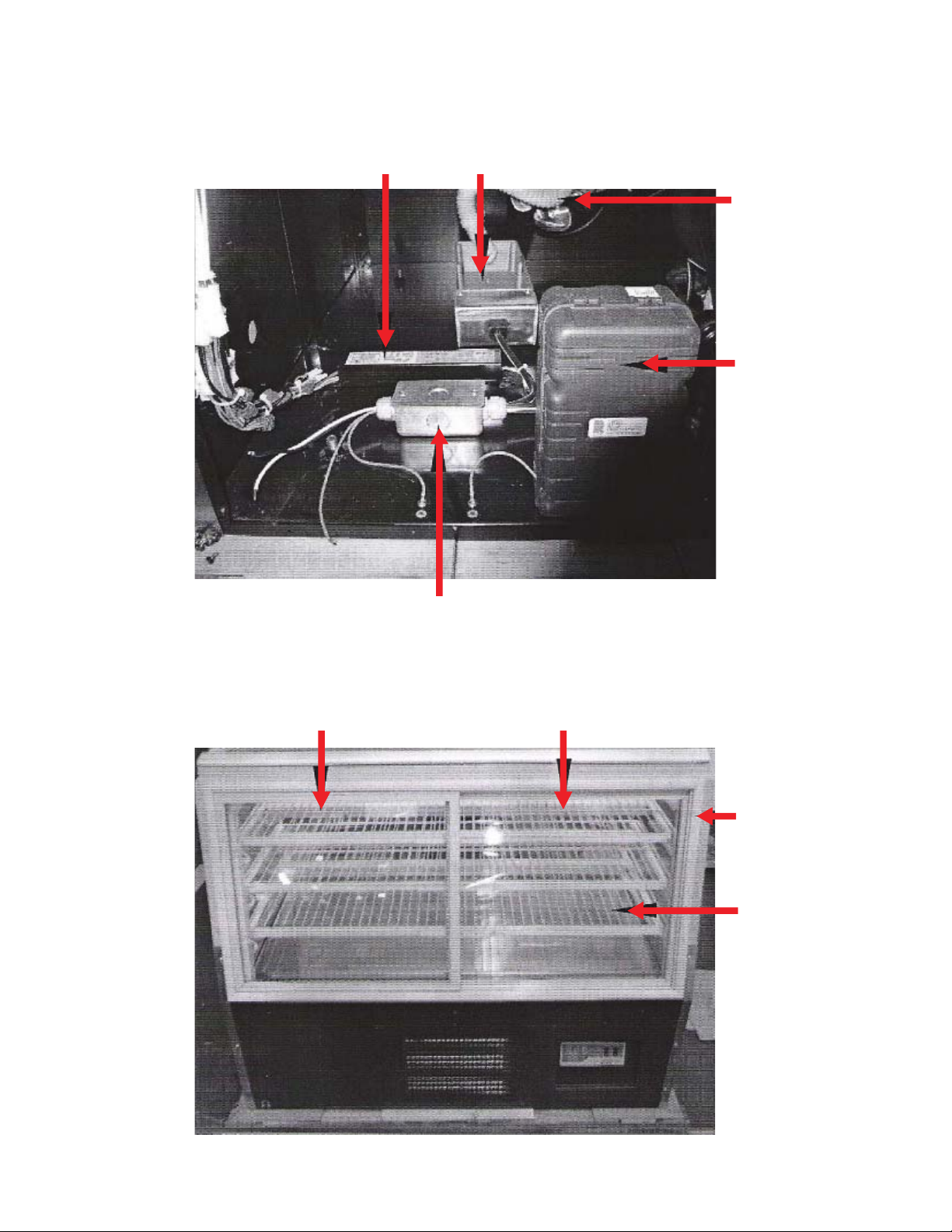
3-10 WIRING AREA
BALLAST F LAMP CONDENSER REMOVE
DRAIN HOSE
COMPRESSOR
ELECT BOX
3-11. BACK DOOR
BACK DOOR LEFT BACK DOOR RIGHT
JOINT BOX
DOOR SASH
GLASS
Page 15
4. MAIN COMPONENTS
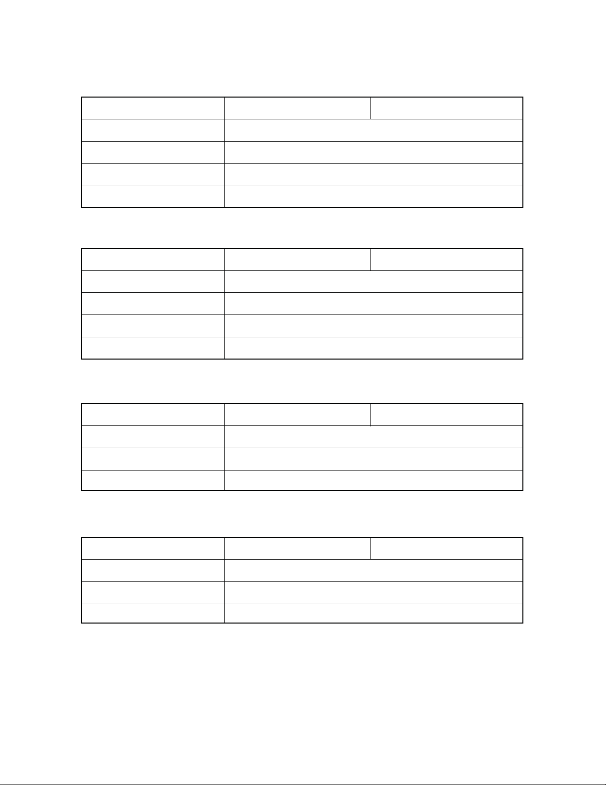
4-1. COMPRESSOR
MODEL
REFRIGERANT
VOLTAGE
COMP MODEL
PART CODE
STARTING TYPE
4-2. LIQUID LINE FILTER
MODEL
REFRIGERANT
PRESSURE
MODEL
PART CODE
TB-4R TB-5R
R-134A
115V / 60HZ
CAJ4476Y (AKA4476YXA)
BS1C001
CSIR
TB-4R TB-5R
R-134A
MIN 610 PSIG
SMGT-7
BS1O300
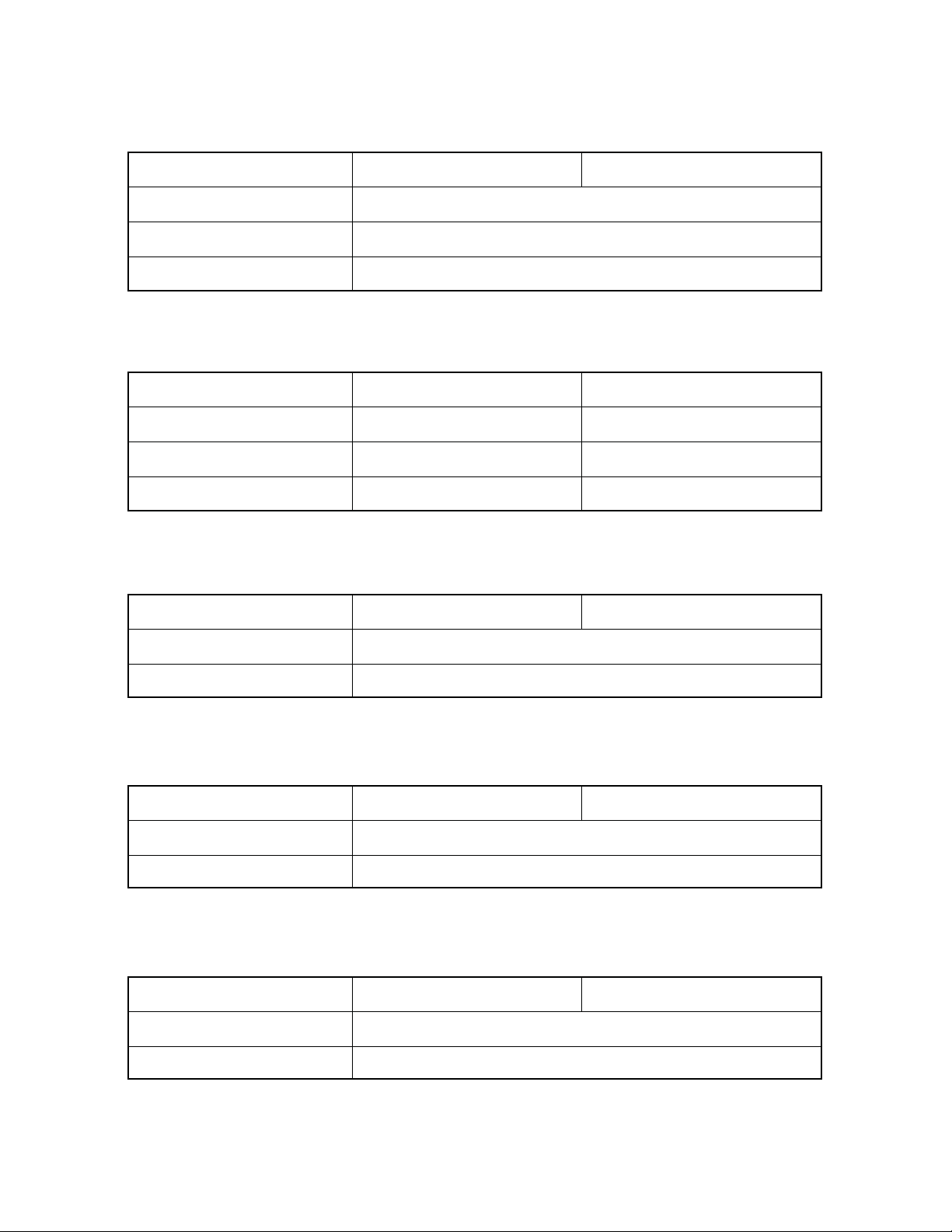
4-3. EXPANSION VALVE
MODEL
REFRIGERANT
VOLTAGE
COMP MODEL
PART CODE
4-4. EVAP & CON’D FAN MOTOR
MODEL
REFRIGERANT
VOLTAGE
COMP MODEL
PART CODE
TB-4R TB-5R
R-134A
1 / 4X1 / 2 IN
ORIF, NO, 4
BS10130
TB-4R TB-5R
R-134A
115V / 60HZ
CAJ4476Y (AKA4476YXA)
BS1C001
Page 16
4-5. CONDENSER FAN BLADE
MODEL
METAL
SPEC
PART CODE
TYPE
4-6. EVAP FAN BLADE
MODEL
METAL
SPEC
PART CODE
TYPE
4-7. POWER SWITCH
TB-4R TB-5R
AL
Ø250 4B
BS1Z149
CCW
TB-4R TB-5R
AL
Ø200 5B
BS1Z148
CCW
MODEL
MARKED
RATING
PART CODE
4-8. CONDENSER REMOVE
MODEL
RATING
MODEL
PART CODE
TB-4R TB-5R
“I” AND “O”
125V, 20FLA, 3/4HP
BS10300
TB-4R TB-5R
117V, 300W
TG12-5000
BS10307
Page 17
4-9. BALLAST F LAMP
MODEL
RATING
MODEL
PART CODE
4-10. FLUORESCENT LAMP
MODEL
RATING
MODEL
PART CODE
4-11. LAMP SOCKET
MODEL
TB-4R TB-5R
120V, 114W
LA432I120EN
BS1C149
TB-4R TB-5R
30W
TL-D30W
BS10303
TB-4R TB-5R
32W
FLR32SS
BS10305
RATING
PART CODE
4-12. MAIN PCB
MODEL
RATING
PART CODE
4-13. DISPLAY PCB
MODEL
RATING
PART CODE
300V, 1A
BS10338
TB-4R TB-5R
115V, 60HZ
BS1X154A
TB-4R TB-5R
115V, 60HZ
BS1X174A
Page 18

4-14. TRANS FORMER
MODEL
RATING
MODEL
PART CODE
4-15. GAS SPRING
MODEL
SPEC
PART CODE
4-16. SERVICE VALVE
MODEL
SPEC
TB-4R TB-5R
AC120V, DC12V
EP-0301D
BS1R100
TB-4R TB-5R
550N
BS10308
TB-4R TB-5R
3/8”
770N
BS10310
PART CODE
BS1C001
Page 19

5. ELEC’T CONTROL INSTRUCTIONS
5-1. REFRIGERATOR CONTROL
5-1-1. HOW TO USE THE DISPLAY PCB PANEL
- LED
- It indicates setting temperature.
- Temperature can ne controlled by the user
- Factory setting is level “normal” setting can
be changed by pressing up/down button.
5-1-2. ERROR CODE
CODE
CONTENT
PERCEPTION METHOD REFRIGERATION STATE
OPEN
TE
T-SENSOR
SHORT
OPEN
CE
C-SENSOR
SHORT
OPEN
SHORT
CE
T-SENSOR
C-SENSOR
- NORMAL OPERATION
- TIME CONTROL
COMP ON : 10 MINUTES
COMP OFF : 10 MINUTES
- NORMAL OPERATION
- TIME CONTROL
COMP ON : 10 MINUTES
COMP OFF : 10 MINUTES
Page 20

5-1-3. FUNCTION TABLE
NO
1
TEMPERATURE
2
FUNCTION
OPERATION
CONTROL
CONTROLLED
PA RT
COMPRESSOR
LED
DESCRIPTION
1. Led displays inside temperaturer
2. Begins to run immediately if higher than
41˚F and begin to run after 5 minutes pause
if lower than 41˚F
1. The Temperature can be changes by
pushing up/down buttons.
2. LED displays inside temperature.
3. Buzzer buzzes 1 time whenever a button
is pressed.
4. Compressor automatically turns on and
o by C-sensor (except error mode)
5. Comp on/o temperature (˚F)
NOTCH
1 (COOL)
(NORMAL)
3
COMP ON COMP OFF SETTING BAR DISPLAY
55˚F
2
4
48˚F
46˚F
43˚F
32˚F
28˚F
25˚F
23˚F
1 (COOL)
2
3
(NORMAL)
4
5 (COLD)
5 (COLD)
39˚F
21˚F
Page 21

6. TROUBLE SHOOTING CHART
6-1. THE REFRIGERATOR DOES NOT COOLING
DOES THE
COMPRESSOR
RUN NORMALLY?
YES
IS THERE A DEFECT
ON WELDING POINT
OF COOLING CYCLE?
NO NO
YES
NO
DOES THE
RATED VOLTAGE
SUPPLY?
NO
CHECK CONTINUITY
POWER CORD
YES
DOES THE
COMPRESSOR RUN
NORMALLY AFTER SHORT
CIRCUIT THE DISPLAY?
YES
NO
DEFECTIVE
MAIN PCB &
THERMISTOR
CHECK TO SEE IF THE
ELECTRICITY BOTH POLES
ON THE OVERLOAD
GLOE WITHOUT
PROBLEM
NO
YESYES
LEAKAGE OF
REFRIGERANT
EXPANSION
VALVE CLOGGED
DEFECTIVE
POWER CORD
DOES THE ELECTRICITY
FUSE FLOW?
YES YES
DOEW THE ELECTRICITY
ON RELAY FLOW?
DEFECTIVE RELAY
DEFECTIVE WIRING DEFECTIVE CAPACITOR
DEFECTIVE
OVERLOAD
NO
Page 22

6-2. THE REFRIGERATOR DOES NOT COOLING WELL
CHECK TO SEE
WHETHER SYSTEM
DOES NOT WORK OR
STOP FREQUENTLY
YES
DEFECTIVE
PCB AND
THERMISTER
NO
CHECK TO SEE IF
THE REFRIGERANT
LEAKAGE
NO
CHECK TO SEE IF
THE FRONT GASKET
LEAKAGE
NO
CHECK TO SEE IF
THE LOCATION OF
SETTING IS NORMAL
NO
YES
YES
WELDING THE
REFRIGERANT LEAK
SEALING SHOULD
BE DONE TO
THE LEAK
DEFECTIVE
CONTROL PCB
NO
YES
CHECK TO SEE IF
THE COOLING EFFECT
WHEN TEMPERATURE
CONTROL IS ON COOL
ADJUSTMENT FOR
TEMP NOTCH
DEFECTIVE FOR THE
CONNECTION POINT
OF PCB
NO
NO
ELMINATE THE
EVAPORATOR
CHECK TO SEE IF
THE FROST FOMS
EXCESSIVELY
NO
MAKE THE AIR
CIRCULATION WELL
CHECK TO SEE IF
THE OVER LOAD WORK
WHEN THE DEGREE OF
SUROUNDINGS
INCREASES
FROST ON
YES
YES
Page 23

6-3. LAMP DOES NOT LIGHT WELL
CHECK THE
CONNECTING POINT
WITH SOCKET
YES
CHECK TO SEE IF
THE LAMP COLOR
CHANGED TO BLACK
YES
DEFECTIVE
LAMP
YES
ADJUST THE LAMP
FOR GOOD
CONNECTION
NO
CHECK TO SEE IF
THE ELECTRICITY
BOTH POIES OF
LAMP FIOW EACH OTHER
YES
CHECK CONTINUITY
OF LAMP SWITCH
YES
DEFECTIVE
NO
DEFECTIVE
LAMP
NO
LAMP
CHECK
CONTINUITY
OF WIRING
YES
DOES THE RATED
VOLAGE SUPPLY
NO
DEFECTIVE
WIRING
Page 24

6-4. WHEN THERE IS A EXCESSIVE NOISE
CHECK TO SEE IF THE
LOCATION FOR
REFRIGERATOR
IS LEVEL PLACE
NO
CHECK OR SET UP
THE REFRIGERATOR AGAIN
(KEPP HORIZONTAL/VERTICAL)
YES
DOES THE HIGH
YES
VOLTAGE SUPPLY?
NO
YES YES
IS THERE A VIBRATION
BETWEEN PIPES
NO
CHECK LOOSENESS
OF SCREW
ADJUST THE
VOLTAGE
ELMINATE
VIBRATION
BETWEEN PIPES
Page 25

7. REFRIGERANT CYCLE DIAGRAM
Page 26

8. REPLACEMENT OF MAIN COMPONENTS
8-1. END GLASS PART
- END GLASS
- END GLASS GASKET SASH
- END GLASS GASKET
A. Open the front glass and then
dissemble the left and right side
gasket as the picture.
B. Remove the xed screw on
top of the side gasket sash.
C. Remove the xed screw on
the lower end of the side
gasket sash.
Page 27

8-2. FRONT GLASS PART
- TOP GLASS CLAMP A
- TOP GLASS CLAMP B
- GAS SPRING
D. Pull out the side glass
as picture.
SIDE GLASS
FRONT GLASS
A. Two person hold the
front glass
B. Remove the xed sixangular
on the top glass clamp by
L-wrench.
TOP GLASS CLAMP B
Page 28

C. Dissamble the Front glass
from the glass clamp.
D. Pull out the glass guide
in a beeline.
FRONT GLASS
TOP GLASS CLAMP B
E. Pull out the top glass clamp
A in a beeline.
Page 29

F. Remove the xed screw on
the back, left and right side
of GLASS CLAMP A.
G. Remove the xed rivet on
the top of COVER FRAME by
drill
COVER FRAME L(R)
H. Cut the silicon that sealing on
the COVER FRAME by the back
of a sword.
Page 30

I. Dissenble COVER FRAME.
UNDER GLASS CLAMP
J. Remover the xed screw on
PIN that xed GAS SPRING.
K. Dissemble the GAS SPRING.
GAS SPRING PIN
Page 31

L. Pull out the GAS SPRING
in the vertical line.
GAS SPRING
M. Remove the xed PIN on
GAS SPRING
SUPPORT R
Page 32

8-3. LATHE TOP COVER PART
- FLUORESCENT LAMP
- LAMP SOCKET
A. Take out the inside and
out side DOOR ASSY.
LATHE TOP COVER
ACYLE COVER C
B. Remove the xed screw
on ACYLE COVER.
C. Pull out ACYLE COVER.
Page 33

SOCKET LAMP CLAMP
D. Pull out the lamp assy from
the socket lamp clamp.
SOCKET LAMP
E. Pull out the socket lamp
from lamp
8-4. WIRE SHELF LATHE PART
- FLUORESCENT LAMP
- LAMP SOCKET
A. Open the front glass.
Page 34

B. Open the back door, take out
holding that connect wire
shelf lathe.
WIRE SHELF LATHE
C. Pull out the shelf.
D. Pull out the wire shelf lathe
from the left and right side hole.
Page 35

E. Pull out the
wire shelf lathe.
F. Remove the lamp assy from
the socket clamp in the back of
wire shelf lathe.
G. Pull out socket lamp
from lamp
FLUORESCENT LAMP
Page 36

8-5. FRONT MOTOR PART
- FAN MOTOR
- FAN BLADE
FRONT COVER B
FRONT PANEL
A. Remove the xed screw on
the lower end front decor
guide B.
B. Pull out front decor guide B
from front panel.
C. Pull out front panel as
picture.
Page 37

D. Remove the xed screw on
the top and lower end of
front cover B.
E. Cut the wire of fan motor.
F. Remove 4 xed screw on the
top and lower end of
fan motor bracket.
Page 38

G. Pull out fan motor assy
H. Remove the xed screw on
the fan motor
I. Take out fan motor B/K
FAN BLADE
Page 39

J. Remove the xed nut on
The fan blade.
K. Dissemble fan blade.
Page 40

8-6. FRONT GASKET PART
- FRONT GASKET SASH
- FRONT GASKET
SIDE GASKET SASH
A. Push the side gasket
as picture.
B. Pull out front gasket
as picture.
C. Remove the xed screw on
the front gasket sash.
Page 41

8-7. REFRIGERATION COMPARTMENT
- COMPRESSOR ASSY
- CONDENSER ASSY
- FAN MOTOR ASSY
- FAN BLADE
- LIQUID LINE FILTER
- SVS VALVE
D. Dissemble front gasket sash
from the body.
A. Remove the xed screw on
machine room cover
which back side of the body.
Page 42

B. Pull out the unit assy.
C. Support with a post after
pull out till show all part.
(pipe broken)
D. Remove the xed screw
on the top and lower end of
fan motor assy.
Page 43

E. Remove the xed screw
on the fan motor.
F. Dissemble fan motor B/K.
G. Dissemble fan motor B/K.
Page 44

8-8. COOLING COMPARTMENT
- THERMISTA ASSY
- EVAPORATOR ASSY
- EXPANSION VALVE
- FAN BLADE
- FAN MOTOR ASSY
A. Remove the xed screw
on the display.
B. Pull out the display pan.
Remove the unit on fan blade.
Page 45

D. Dissenble the fan blade.
E. Remove the xed screw on
the side that hold
evap fan cover.
F. Open the back door remove
the xed screw on the left
and right side of fan motor.
Page 46

G. Pull out evap fan cover.
H. Remove the xed screw on
the left and right side of
fan motor.
I. Dissemble fan motor.
Page 47

8-9. CONTROL BACK PART
- MAIN PCB ASSY
- DISPLAY PCB ASSY
- POWER SWITCH
- TRANS FORMER
A. Remove the xed screw on
the control back panel assy.
B. Remove the xed screw on
the top and lower end of the
control panel and back panel.
C. Open the control back panel.
Page 48

D. Opening control part.
E. Dissemble the housing
on the main PCB
F. Remove the xed screw on
the main PCB.
Page 49

G. Remove the xed screw on
the display PCB.
H. Remove the xed screw on
the trans former.
I. While pushing the power
switch leaking circumference
pull out it.
Page 50

8-10. MAIN WIRING PART
- BALLAST F LAMP
- CONDENSER REMOVE
- POWER CORD
8-10-1. CONDENSER REMOVE
A. Remove the xed screw on
the left side of back cover.
WIRING LAMP HOUSHIG
(Wiring opening)
Page 51

B. Pull out cord on the
condenser remove.
C. Little twist and then pull
out the condenser remove.
8-10-2. BALLAST F LAMP
A. Remove the xed screw on
the ballast f lamp.
Page 52

B. Pull out the ballast f lamp.
C. Cut the cable tie for wire.
D. Cut the wire of already
disconnected ballast f lamp.
Page 53

9. PART LIST
PART NAME
FRONT GLASS
FRONT GLASS
GAS SPRING
GAS SPRING
LIQUID LINE FILTER
SVS VALVE
END GLASS
BACK DOOR LF ASSY
BACK DOOR LF ASSY
BACK DOOR RH ASSY
BACK DOOR RH ASSY
CORD DESCRIPTION MODEL
BS10312
BS10313
BS10308
BS10310
BS10300
BS1C004
BS1D147
BS1D400A
BS1D400A
BS1D402A
BS1D402A
RD PVC & GLASS
RD PVC & GLASS
RD PVC & GLASS
RD PVC & GLASS
T6
T6
550N
770N
R-134A
3/8”
PAIR
TB-4R
TB-5R
TB-4R
TB-5R
USE FOR PUBLIC
USE FOR PUBLIC
USE FOR PUBLIC
TB-4R
TB-5R
TB-4R
TB-5R
BALLAST F LAMP
FLUORESCENT LAMP
FLUORESCENT LAMP
CONDENSER REMOVE
COMPRESSOR
CONDENSER ASSY
EVAPORATOR
EVAPORATOR
POWER SWITCH
ACYEL COVER A
BS1C149
BS10303
BS10305
BS10307
BS1C001
BS1X194A
BS1X112A
BS1X111A
BS10309
BS1M104
120V, 32W
30W
32W
117V, 600W
CAJ4476Y
CU PIPE & AL FIN
CU PIPE & AL FIN
CU PIPE & AL FIN
125V, 20FLA
T5
USE FOR PUBLIC
TB-4R
TB-5R
USE FOR PUBLIC
USE FOR PUBLIC
USE FOR PUBLIC
TB-4R
TB-5R
USE FOR PUBLIC
TB-4R
Page 54

PART NAME
CORD DESCRIPTION MODEL
ACYEL COVER A
ACYEL COVER B
ACYEL COVER C
ACYEL COVER C
WIRE LATHE TOP
WIRE LATHE TOP
WIRE LATHE MID
WIRE LATHE MID
WIRE LATHE BOTT
WIRE LATHE BOTT
SIDE GLASS SASH
SIDE GLASS GASKET
BS1M166
BS1M105A
BS1M266
BS1M267
BS1W166
BS1W169
BS1W167
BS1W171
BS1W168
BS1W173
BST323
BST324A
T5
T3
T5
T5
MSWR10 & PVC WHT
MSWR10 & PVC WHT
MSWR10 & PVC WHT
MSWR10 & PVC WHT
MSWR10 & PVC WHT
MSWR10 & PVC WHT
MD PVC WHT
SF PVC WHT
TB-5R
USE FOR PUBLIC
TB-4R
TB-5R
TB-4R
TB-5R
TB-4R
TB-5R
TB-4R
TB-5R
USE FOR PUBLIC
USE FOR PUBLIC
FRONT GASKET
FRONT GASKET
FRONT GASKET SASH
FRONT GASKET SASH
LAMP SOCKET ASSY
BACK DOOR FRAME A
BACK DOOR FRAME A
BACK FRAME SASH B
FAN MOTOR
BST324B
BST324C
BST325
BST326
BS10339
BS1T120A
BS1T208A
BS1T206A
BS1C136
SF PVC WHT
SF PVC WHT
RD PVC WHT
RD PVC WHT
300V, 1A
RD PVC GRY
RD PVC GRY
RD PVC GRY
115V, 9W, CCW
TB-4R
TB-5R
TB-4R
TB-5R
USE FOR PUBLIC
TB-4R
TB-5R
USE FOR PUBLIC
Page 55

PART NAME
CORD DESCRIPTION MODEL
COND FAN BLADE
EVAP FAN BLADE
THERMISTOR ASSY
MAIN PCB ASSY
DISPLAY PCB ASSY
TRANS FORMER
GLASS CLAMP
GLASS CLAMP
FRONT PANEL
FRONT PANEL
SIDE PANEL
COVER FRAME L
BS1Z149
BS1Z148
BS1C152
BS1X154A
BS1X174A
BS1R100
BS1W155A
BS1W156A
BS1V103A
BS1V029A
BS1W156A
BS1T098A
ø250 CCW
ø250 CCW
MICOM PROGRAM
DIGITAL NOTCH 5
DC12V
AL
AL
BLK VINYL G1 T1
BLK VINYL G1 T1
BLK VINYL G1 T1
ABS GRY T1 5
USE FOR PUBLIC
USE FOR PUBLIC
USE FOR PUBLIC
USE FOR PUBLIC
USE FOR PUBLIC
USE FOR PUBLIC
TB-4R
TB-5R
TB-5R
TB-4R
USE FOR PUBLIC
USE FOR PUBLIC
COVER FRAME R
TOP COVER FRAME
TOP COVER FRAME
BS1T099A
BS1T096A
BS1T098A
ABS GRY T1 5
ABS GRY T1 5
ABS GRY T1 5
USE FOR PUBLIC
TB-4R
TB-5R
 Loading...