

Page 1

Commercial
Refrigerator
Service Manual
Under Counter Table / Series Salad / Dual Table Series
KUR9-1 KUF9-1 KGR9-1 KHR9-1 KSR9-1
KUR12-2 KUF12-2 KGR12-2 KHR12-2 KSR12-2 KURF12-2
KUR15-2 KUF15-2 KGR15-2 KHR15-2 KSR15-2 KURF15-2
KUR18-3 KUF18-3 KGR18-3 KHR18-3 KSR18-3 KURF18-3
Page 2

1
TABLE OF CONTENTS
Section 1 General Information ................................................................................................................................................................................ 4
1-1. How to use Power Cord ? .......................................................................................................................................................................... 4
1-2. How to disconnect the power cord? .................................................................................................................................................... 4
Section 2 Installation Instructions .......................................................................................................................................................................... 5
2-1. How to remove packing instructions.................................................................................................................................................... 5
2-2. Location Product ............................................................................................................................................................................................ 6
Section 3 ............................................................................................................................................................................................................................... 7
Product Instructions ......................................................................................................................................................................................................... 7
3-1. EXPLODE VIEW ................................................................................................................................................................................................ 7
3-1-1. KUR 9-1 / KUF9-1/KGR9-1 Explode View ............................................................................................................................. 7
3-1-2. KHR 9-1 /KSR9-1 Explode View ................................................................................................................................................ 8
3-1-3. KUR12-2/ KUF12-2/KGR12-2 Explode View ......................................................................................................................... 9
3-1-4. KHR12-2/KSR12-2 Explode View ............................................................................................................................................. 10
3-1-5. KURF12-2 Explode View .............................................................................................................................................................. 12
3-1-6. KUR15-2/ KUF15-2/KGR15-2 Explode View ....................................................................................................................... 13
3-1-7. KHR15-2/KSR15-2 Explode View ............................................................................................................................................. 14
3-1-8. KURF15-2 Explode View .............................................................................................................................................................. 15
3-1-9. KUR18-3/ KUF18-3/KGR18-3 Explode View ....................................................................................................................... 16
3-1-10. KHR18-3/KSR18-3 Explode View .......................................................................................................................................... 17
3-1-11. KURF18-3Explode View ............................................................................................................................................................. 19
3-2. Wiring Diagram ............................................................................................................................................................................................. 20
3-2-1 (KUR 9-1, KUR12-2, KUR15-2, KUR18-3 KGR 9-1, KGR12-2, KGR15-2, KGR18-3) ...................................................... 20
3-2-2. Wiring Diagram (KUF 9-1, KUF12-2, KUF15-2, KUF18-3) ..................................................................................................... 20
3-2-3. Wiring Diagram (KHR 9-1, KHR12-2, KHR15-2, KHR18-3 KSR 9-1, KSR12-2, KSR15-2, KSR18-3) .................... 21
3-2-4. Wiring Diagram ( KURF12-2, KURF15-2, KURF18-3) ............................................................................................................... 21
3-4. PCB Control Instruction ............................................................................................................................................................................. 22
Page 3

2
3-3-1. Basic Operation ............................................................................................................................................................................... 22
3-4. PCB Function Manual ................................................................................................................................................................................. 23
3-4-1.How to set up manual defrost .................................................................................................................................................. 23
3-4-2. How to remove the manual defrosting ............................................................................................................................... 23
3-4-3. How to set up the correction of inside temperature .................................................................................................... 24
3-4-4. Correction Temperature on Display PCB ............................................................................................................................. 24
3-4-5. Change Model ................................................................................................................................................................................. 25
3-4-6. Change the defrost cycle ............................................................................................................................................................ 25
3-4-7. Change the deforst temperature ............................................................................................................................................ 26
3-4-8. Change Temperature showing method ............................................................................................................................... 26
3-4-9. Control Eva fan motor.................................................................................................................................................................. 27
3-4-10. Verify Error Code .......................................................................................................................................................................... 27
3-5. PCB function instructionDry –type model ( REF / FRE) ............................................................................................................. 28
3-6. COMPRESSOR running、starting、stopping .................................................................................................................................. 28
3-6-1. COMP running ................................................................................................................................................................................. 28
Section 4 Replacement Of Main Components .............................................................................................................................................. 29
4-1. Mullion Heater replacement ................................................................................................................................................................... 29
4-2. Cabinet Heater replacement ................................................................................................................................................................... 30
4-3. Refrigeration compartment replacement ......................................................................................................................................... 32
4-4.Remove Counter Top ................................................................................................................................................................................... 33
4-5.Remove Evap Motor ..................................................................................................................................................................................... 34
4-6.Remove Evaporator ....................................................................................................................................................................................... 35
Section 5 Customer Support .................................................................................................................................................................................. 36
5-1. MAIN COMPONENTS ................................................................................................................................................................................. 36
5-1-1.COMPRESSOR .................................................................................................................................................................................... 36
5-1-2.COMPRESSOR RELAY, OVERLOAD ........................................................................................................................................... 36
5-1-3.COMPRESSOR CAPACITOR .......................................................................................................................................................... 37
Page 4

3
5-1-4.CONDENSER FAN MOTOR ........................................................................................................................................................... 37
5-1-5.EVAPORATOR FAN MOTOR ......................................................................................................................................................... 37
5-2. Filter Dryer .................................................................................................................................................................................................... 38
5-3. Defrost Heater ............................................................................................................................................................................................. 38
5-4. Thermal Fuse ................................................................................................................................................................................................ 38
5-5. Capillary Tube Spec .................................................................................................................................................................................. 39
5-6. The cycle pressure of model starting (refrigerant weight) ..................................................................................................... 39
5-7. Service Part list
Page 5
4
Section 1 General Information
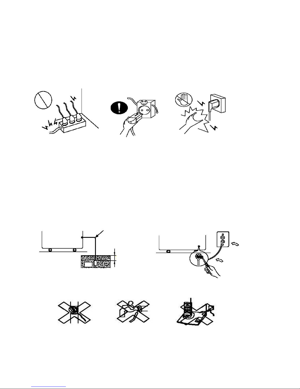
1-1. How to use Power Cord ?
1-1-1. Be sure not put more plug in the socket. Please use the dedicated outlet.
-Overheated wire, which will cause fire or start malfunction
1-1-2. Wet hands off the power.
- Life is in danger
1-2. How to disconnect the power cord?
☞ To prohibit leakage or electric shock, please use the prescript method to connect ground.
1-2-1. If there are grounds connectors for 220v units, units don’t need ground while outlet is for AC 220v. (Please
make sure that there are grounds in buildings, then units can use AC 220v outlets with grounds connectors.)
1-2-2. The power is 220v without ground connector, use dedicated outlet to ground.
A. Please connect earth wire to copper, which will be covered under moisture ground. (The depth is more than
17cm)
- copper item : thickness : >0.7mm square: >900cm2
B. Please connect the dedicated ground outlet.
1-2-3. Prohibition ground places
Gas pipe Water-pipe Telephone lines
Page 6
5
Section 2 Installation Instructions
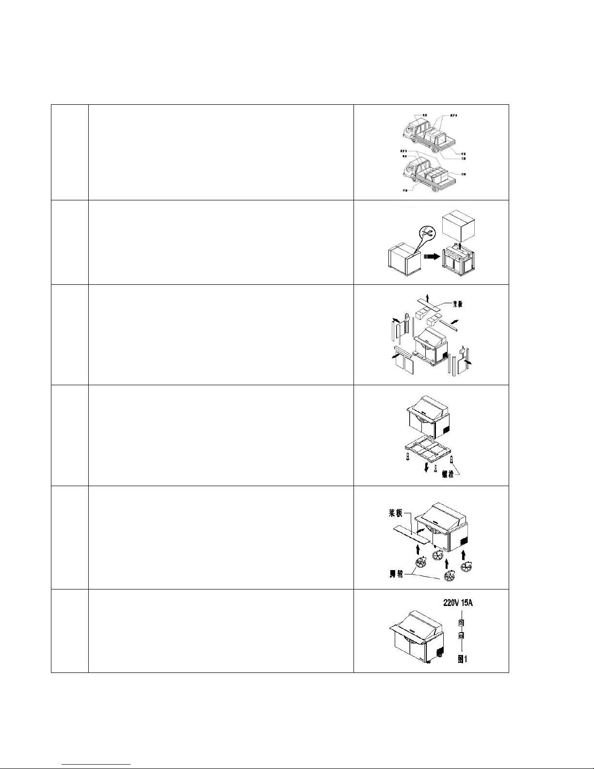
2-1. How to remove packing instructions
1
Please set doors of products towards the same direction, tie
the packing stick with ropes.
2
Please cut the PE bag, then remove the packing box.
3
Please remove all the packing parts around the products.
4
Lift up the product, disassemble four screws, then remove
the packing base.
5
Install the fours casters, insert the kitchen board into the
slot.
6
Caution: 1> Please use dedicated outlet.
2> Please let the unit is grounded while you work.
3> Please connect the power with leakage
protector.
Page 7
6
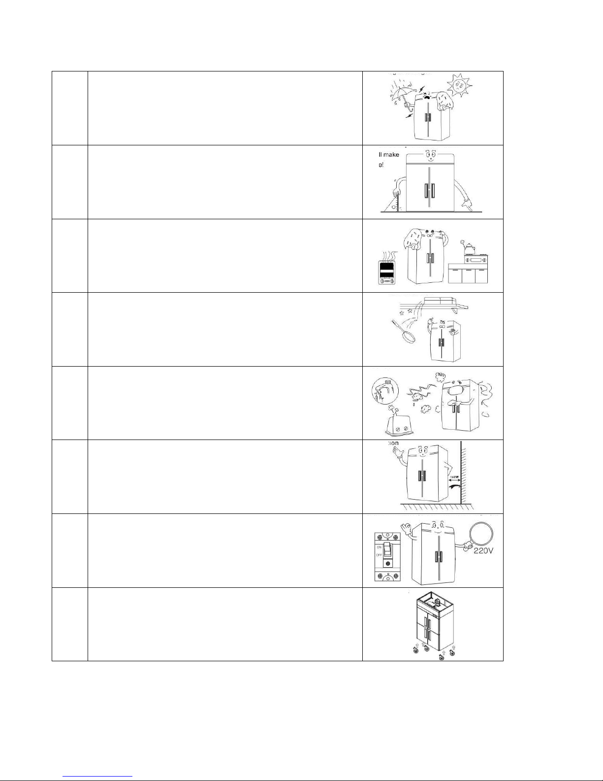
2-2. Location Product
1
Be sure to set the unit in door!
To prevent damage, leakage!
2
Be sure that the location be chosen has a strong enough
floor to support total weight of the cabinet and any other
contents.
The uneven will make noise and shake!
3
Be sure to avoid corrosive environment!
It will shorten the life of the unit
4
Be sure no object is on top of the product!
The objects will fall to hit the unit!
5
Be sure to avoid damp and dusty environment!
Electric shock
6
Be sure the unit is away from the wall at least 15 ㎝!
Good air circulation
7
Be sure the power cord is connected to the proper voltage!
The Product is special for 220V
It can’t be used with the voltage of 110V
Please connect the power with leakage protector!
8
Please use the casters or legs.
Page 8
7
Section 3
Product Instructions
3-1. EXPLODE VIEW
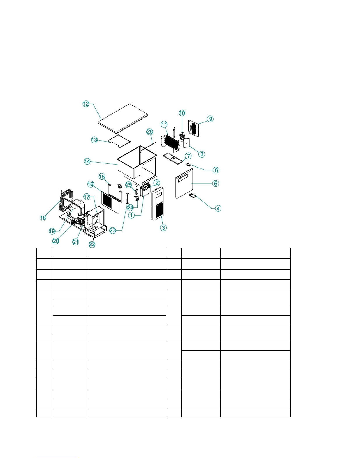
3-1-1. KUR 9-1 / KUF9-1/KGR9-1 Explode View
NO
Part Cord
Part Name
No
Part Cord
Part Name
1
KR81410400
MAIN PCB
14
KU91100100
CABINET ASSY
2
KR81410300
FRONT PCB
15
KR92100302
UNIT BRACKET
3
KR81410704
UNIT FRONT COVER
16
KR81900104
UNIT SAID COVER
4
KR89910100
BOTTOM HINGE(R)
17
KF24900105
CONDENSER ASSYREF
30229M0405
BOTTOM HINGE(R)GLASS
5
KR5AF00102
DOOR(R)_1500
18
KF84900105
CONDENSER ASSYFRE
JG5AF00206
ASS'Y GLASS DOOR R
KR94200109
SUCTION PIPE(B)REF
6
KR89910402
TOP HINGE(R)
19
KR84200109
SUCTION PIPE(B)FRE
M722900108
TOP HINGE(R)GLASS
G2R5700200
COMP REF LX110 REF
7
KR91800201
EVAP DRAIN GUIDE
20
G5R5700200
COMP FRE LX125 FRE
BR84100100
FILTER DRYER
8
KR91800102
AIR GUIDE(L/R)
21
M729300102
DRAIN PAN
9
KF81700100
EVA DUCT
22
G8F5000200
CONDENSER FAN OTOR
10
G8F5000100
EVA FAN MOTOR
23
KF82100208
UNIT SIDE BRACKET(A)
11
DK9A100103
EVAP-ASSY(공용)
24
K3F3200901
LEVEL FOOT&CASTER
12
KR9FF00100
COUNTER TOP
25
KG81200100
SMPS
13
KF85220305
EVA FAN AIR GUIDE
26
KG99600102
LED LAMP
Page 9

8
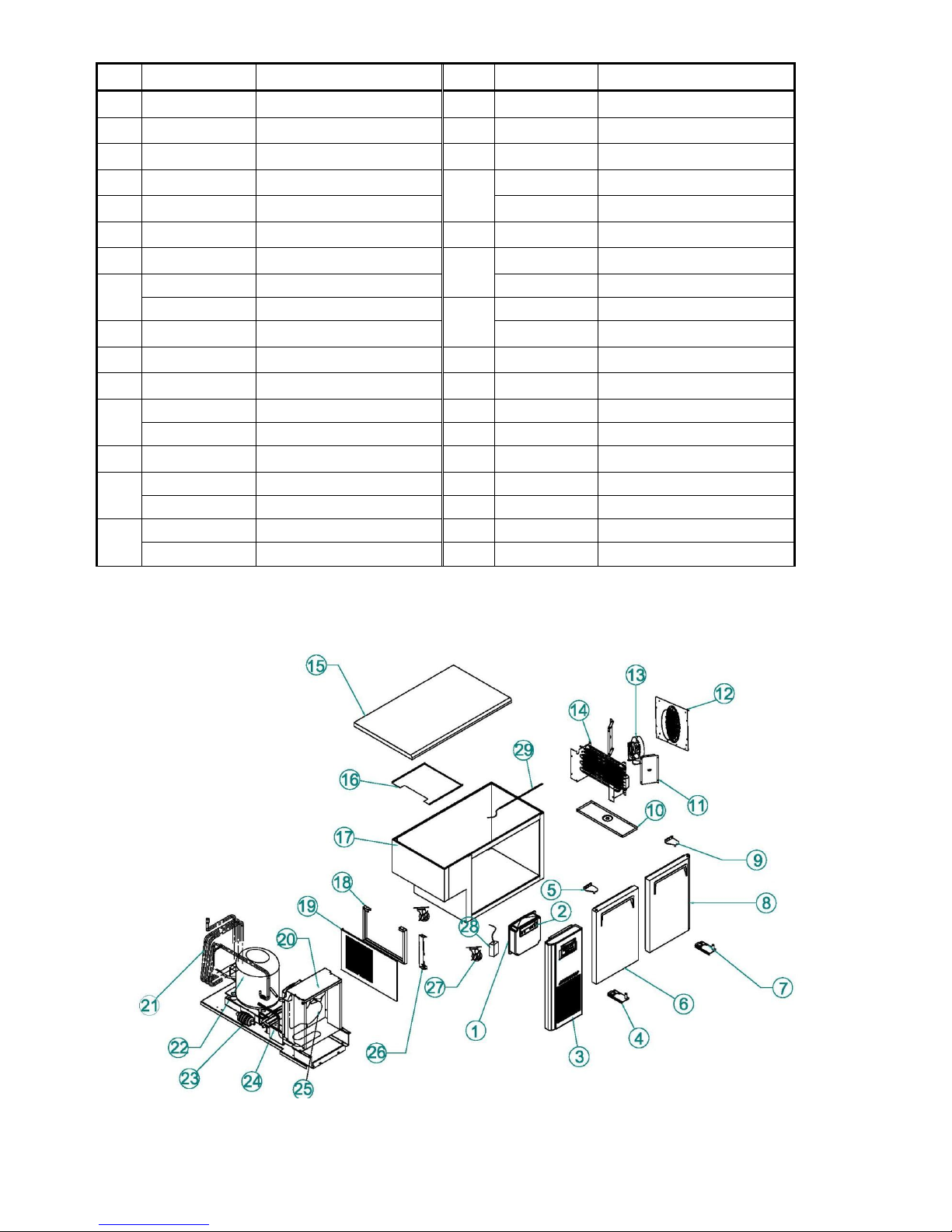
3-1-2. KHR 9-1 /KSR9-1 Explode View
KHR9-1
KSR9-1
Page 10
9
No
Part Cord
Part Name
No
Part Cord
Part Name
1
KR81410400
MAIN PCB
16
BR9AB00100
CABINET ASSY
2
KR81410300
FRONT PCB
17
KR92100302
UNIT BRACKET
3
KR81410704
UNIT FRONT COVER
18
KR81900104
UNIT SAID COVER
4
KR89910100
BOTTOM HINGE(R)
19
KF24900105
CONDENSER ASSY 9 12 15
5
KR5AF00102
DOOR(R)_1500
KF84900105
CONDENSER ASSY 18
6
KR89910402
TOP HINGE(R)
20
BR94200206
SUCTION PIPE(B)
7
U609000103
FAN COVER
21
G2R5700200
COMP REF LX110 9 12 15
8
BR91H00100
EVA DUCT KHR
G5R5700200
COMP FRE LX125 18
BR91700106
EVA DUCT KSR
22
23
BR84100100
FILTER DRYER
9
CM25000101
EVA FAN MOTOR
M729300102
DRAIN PAN
10
BR9AD00103
EVAP-ASSY
24
G8F5000200
CONDENSER FAN MOTOR
11
BR91900103
EVA DRAIN GUIDE
25
KF82100208
UNIT SIDE BRACKET(A)
12
S722500104
PAN GUIDE
26
K3F3200901
LEVEL FOOT&CASTER
BR81800400
PAN GUIDE
27
S728900302
HOOD LID
13
BR81800301
PAN GUIDE
28
S725600501
HOOD
14
BS90900100
PAN SUPPORTER KHR
BR91800200
PAN SUPPORTER KSR
15
BS9FE00100
COUNTER TOP KHR
BR9FF00100
COUNTER TOP KSR
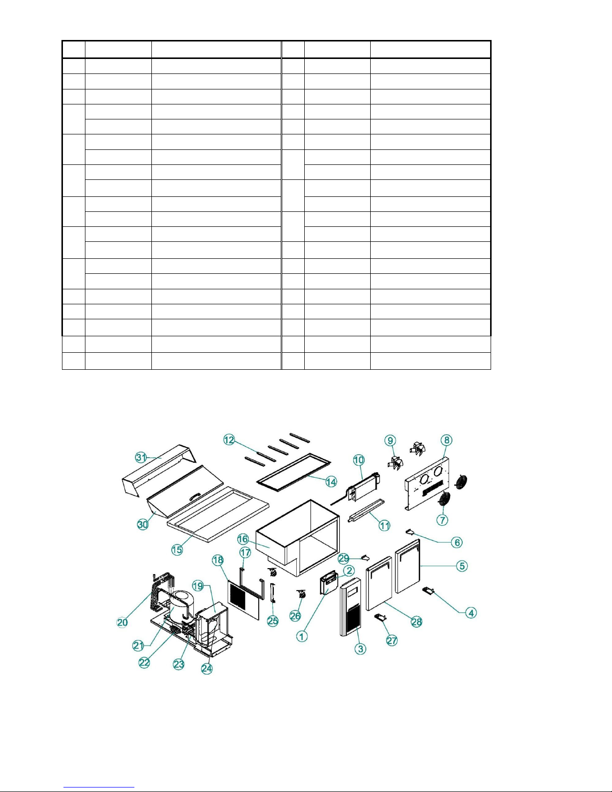
3-1-3. KUR12-2/ KUF12-2/KGR12-2 Explode View
Page 11
10
No
Part Cord
Part Name
No
Part Cord
Part Name
1
KR81410400
MAIN PCB
14
DK84400107
EVAP ASSY FRE
2
KR81410300
FRONT PCB
15
KR2FF00100
COUNTER TOP
3
KR81410704
UNIT FRONT COVER
16
KF85220305
EVAP FAN AIR GUIDE
4
KR89940100
BOTTOM HINGE(L)
17
KU21000100
CABINET ASSY
30229M0305
BOTTOM HINGE(L)GLASS
18
KR92100301
UNIT BRACKET
5
KR89910302
TOP HINGE(L)
19
KR81900104
UNIT SAID COVER
M722900208
TOP HINGE(L)GLASS
20
KF24900105
CONDENSER ASSY REF
6
KR2AF00202
DOOR(L)_1200
KF84900105
CONDENSER ASSY FRE
JG2AF00105
ASS'Y GLASS DOOR L
21
KR94200109
SUCTION PIPE(B) REF
7
KR89910100
BOTTOM HINGE(R)
KR84200109
SUCTION PIPE(B) FRE
30229M0405
BOTTOM HINGE(R)GLASS
22
G2R5700200
COMP LX110 REF
8
KR2AF00102
DOOR(R)_1200
G5R5700200
COMP LX125 FRE
JG2AF00205
ASS'Y GLASS DOOR R
23
BR84100100
DRYER
9
KR89910402
TOP HINGE(R)
24
M729300102
DRAIN PAN
M722900108
TOP HINGE(R)GLASS
25
G8F5000200
CONDENSER FAN MOTOR
10
KR91800201
EVAP DRAIN GUIDE
26
KF82100208
UNIT BRACKET(A)
11
KR91800102
AIR GUIDE(L/R)
27
K3F3200901
LEVEL FOOT&CASTER
12
KF81700100
EVA DUCT
28
KG81200100
SMPS
13
G8F5000100
EVA FAN MOTOR
29
KG99600102
LED LAMP
14
DK9A100103
EVAPASSY REF
3-1-4. KHR12-2/KSR12-2 Explode View
KHR12-2
Page 12
11
KSR12-2
No
Part Cord
Part Name
No
Part Cord
Part Name
1
KR81410400
MAIN PCB
16
BR2AB00100
CABINET ASSY
2
KR81410300
FRONT PCB
17
KR92100302
UNIT BRACKET
3
KR81410704
UNIT FRONT COVER
18
KR81900104
UNIT SAID COVER
4
5
KR89910100
BOTTOM HINGE(R)
19
KF24900105
CONDENSER ASSY REF
KR2AF00102
DOOR(R)_1200
KF84900105
CONDENSER ASSY FRE
6
7
KR89910402
TOP HINGE(R)
20
BR24200105
SUCTION PIPE(B) 12 15
U609000103
FAN COVER
21
G2R5700200
COMP REF LX110 REF
8
BR21H00100
EVA DUCT KHR
G5R5700200
COMP FRE LX125 FRE
BR21700107
EVA DUCT KSR
22
BR84100100
FILTER DRYER
9
CM25000101
EVA FAN MOTOR
23
M729300102
DRAIN PAN
10
BR2AD00103
EVAP-ASSY
24
G8F5000200
CONDENSER FAN OTOR
11
BR21900104
EVA DRAIN GUIDE
25
KF82100208
UNIT SIDE BRACKET(A)
12
S722500104
PAN GUIDE
26
K3F3200901
LEVEL FOOT&CASTER
BR81800400
PAN GUIDE
27
KR89940100
BOTTOM HINGE(L)
13
BR81800301
PAN GUIDE
28
KR2AF00202
DOOR(L)_1200
14
BS20900100
PAN SUPPORTER KHR
29
KR89910302
TOP HINGE(L)
BR21800200
PAN SUPPORTER KSR
30
S488900302
HOOD LID
15
BS2FE00100
COUNTER TOP KHR
31
S485600202
HOOD
BR2FF00100
COUNTER TOP KSR
Page 13
12
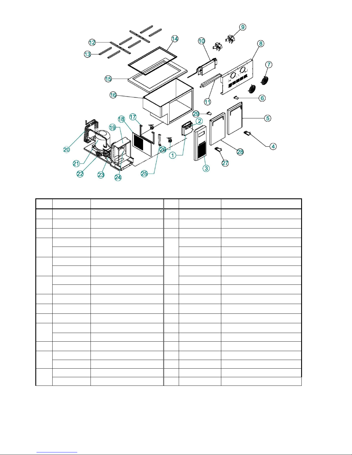
3-1-5. KURF12-2 Explode View
No
Part Cord
Part Name
No
Part Cord
Part Name
1
KRF2500700
MAIN PCB
15
KR2FF00100
COUNTER TOP
2
KRF2500600
FRONT PCB
16
KF85220305
EVAP FAN AIR GUIDE
3
KR81410704
UNIT FRONT COVER
17
KRF2000100
CABINET ASSY
4
KR89940100
BOTTOM HINGE(L)
18
KR92100301
UNIT BRACKET
5
KR89910302
TOP HINGE(L)
19
KR81900104
UNIT SAID COVER
6
KR2AF00202
DOOR(L)_1200
20
KF84900105
CONDENSER ASSY
7
KR89910100
BOTTOM HINGE(R)
21
KRF2600201
SUCTION PIPE(B)
8
KR2AF00102
DOOR(R)_1200
22
G5R5700200
COMP LX125
9
KR89910402
TOP HINGE(R)
23
BR84100100
DRYER
10
KRF2900100
EVA DRAIN GUIDE REF
24
M729300102
DRAIN PAN
KR91800203
EVA DRAIN GUIDE FRE
25
G8F5000200
CONDENSER FAN MOTOR
11
U609000103
FAN COVER REF
26
KF82100208
UNIT BRACKET(A)
12
KRF2100400
EVAP DUCT REF
27
K3F3200901
LEVEL FOOT&CASTER
KF81700104
EVAP DUCT FRE
28
KG81200100
SMPS
13
CM25000101
EVA FAN MOTOR REF
29
KG99600102
LED LAMP
G8F5000100
EVA FAN MOTOR FRE
30
KR91800102
AIR GUIDE(L/R)
14
KRF1222100
EVAP ASSY REF
31
K1D6900100
STRING MOTOR
DK9AI00104
EVAP ASSY FRE
Page 14

13
3-1-6. KUR15-2/ KUF15-2/KGR15-2 Explode View
No
Part Cord
Part Name
No
Part Cord
Part Name
1
KR81410400
MAIN PCB
14
DK84400107
EVAP ASSY FRE
2
KR81410300
FRONT PCB
15
KR2FF00100
COUNTER TOP
3
KR81410704
UNIT FRONT COVER
16
KF85220305
EVAP FAN AIR GUIDE
4
KR89940100
BOTTOM HINGE(L)
17
KU21000100
CABINET ASSY
30229M0305
BOTTOM HINGE(L)GLASS
18
KR92100301
UNIT BRACKET
5
KR89910302
TOP HINGE(L)
19
KR81900104
UNIT SAID COVER
M722900208
TOP HINGE(L)GLASS
20
KF24900105
CONDENSER ASSY REF
6
KR5AF00202
DOOR(L)_1500
KF84900105
CONDENSER ASSY FRE
JG5AF00105
ASS'Y GLASS DOOR L
21
KR94200109
SUCTION PIPE(B) REF
7
KR89910100
BOTTOM HINGE(R)
KR84200109
SUCTION PIPE(B) FRE
30229M0405
BOTTOM HINGE(R)GLASS
22
G2R5700200
COMP LX110 REF
8
KR5AF00102
DOOR(R)_1500
G5R5700200
COMP LX125 FRE
JG5AF00205
ASS'Y GLASS DOOR R
23
BR84100100
DRYER
9
KR89910402
TOP HINGE(R)
24
M729300102
DRAIN PAN
M722900108
TOP HINGE(R)GLASS
25
G8F5000200
CONDENSER FAN MOTOR
10
KR91800201
EVAP DRAIN GUIDE
26
KF82100208
UNIT BRACKET(A)
11
KR91800102
AIR GUIDE(L/R)
27
K3F3200901
LEVEL FOOT&CASTER
12
KF81700100
EVA DUCT
28
KG81200100
SMPS
13
G8F5000100
EVA FAN MOTOR
29
KG59600102
LED LAMP
14
DK9A100103
EVAPASSY REF
Page 15

14
3-1-7. KHR15-2/KSR15-2 Explode View
KHR15-2
KSR15-2
No
Part Cord
Part Name
No
Part Cord
Part Name
1
KR81410400
MAIN PCB
16
BR5AB00100
CABINET ASSY
2
KR81410300
FRONT PCB
17
KR92100302
UNIT BRACKET
3
KR81410704
UNIT FRONT COVER
18
KR81900104
UNIT SAID COVER
4
5
KR89910100
BOTTOM HINGE(R)
19
KF24900105
CONDENSER ASSY REF
KR5AF00102
DOOR(R)_1500
19
KF84900105
CONDENSER ASSY FRE
Page 16

15
6
KR89910402
TOP HINGE(R)
20
BR24200105
SUCTION PIPE(B) 12 15
7
U609000103
FAN COVER
21
G2R5700200
COMP REF LX110 REF
8
BR51H00100
EVA DUCT KHR
G5R5700200
COMP FRE LX125 FRE
BR51700108
EVA DUCT KSR
22
BR84100100
FILTER DRYER
9
CM25000101
EVA FAN MOTOR
23
M729300102
DRAIN PAN
10
BR2AD00103
EVAP-ASSY
24
G8F5000200
CONDENSER FAN OTOR
11
BR21900104
EVA DRAIN GUIDE
25
KF82100208
UNIT SIDE BRACKET(A)
12
S722500104
PAN GUIDE
26
K3F3200901
LEVEL FOOT&CASTER
BR81800400
PAN GUIDE
27
KR89940100
BOTTOM HINGE(L)
13
BR81800301
PAN GUIDE
28
KR5AF00202
DOOR(L)_1500
14
BS50900100
PAN SUPPORTER KHR
29
KR89910302
TOP HINGE(L)
BR51800200
PAN SUPPORTER KSR
30
BS50200100
HOOD LID
15
BS5FE00100
COUNTER TOP KHR
31
BS50100100
HOOD
BR5FF00100
COUNTER TOP KSR
3-1-8. KURF15-2 Explode View
No
Part Cord
Part Name
No
Part Cord
Part Name
1
KRF2500700
MAIN PCB
15
KR5FF00100
COUNTER TOP
2
KRF2500600
FRONT PCB
16
KF85220305
EVAP FAN AIR GUIDE
3
KR81410704
UNIT FRONT COVER
17
KRF5000100
CABINET ASSY
4
KR89940100
BOTTOM HINGE(L)
18
KR92100301
UNIT BRACKET
5
KR89910302
TOP HINGE(L)
19
KR81900104
UNIT SAID COVER
Page 17

16
6
KR5AF00202
DOOR(L)_1500
20
KF84900105
CONDENSER ASSY
7
KR89910100
BOTTOM HINGE(R)
21
KRF2600201
SUCTION PIPE(B)
8
KR5AF00102
DOOR(R)_1500
22 NEK2150GK
9
KR89910402
TOP HINGE(R)
23
BR84100100
DRYER
10
KRF5900100
EVA DRAIN GUIDE REF
24
M729300102
DRAIN PAN
KR91800203
EVA DRAIN GUIDE FRE
25
G8F5000200
CONDENSER FAN MOTOR
11
U609000103
FAN COVER REF
26
KF82100208
UNIT BRACKET(A)
12
KRF5200400
EVAP DUCT REF
27
K3F3200901
LEVEL FOOT&CASTER
KF81700104
EVAP DUCT FRE
28
KG81200100
SMPS
13
CM25000101
EVA FAN MOTOR REF
29
KG99600102
LED LAMP
G8F5000100
EVA FAN MOTOR FRE
30
KR91800102
AIR GUIDE(L/R)
14
KRF1522100
EVAP ASSY REF
31
K1D6900100
STRING MOTOR
DK9AI00104
EVAP ASSY FRE
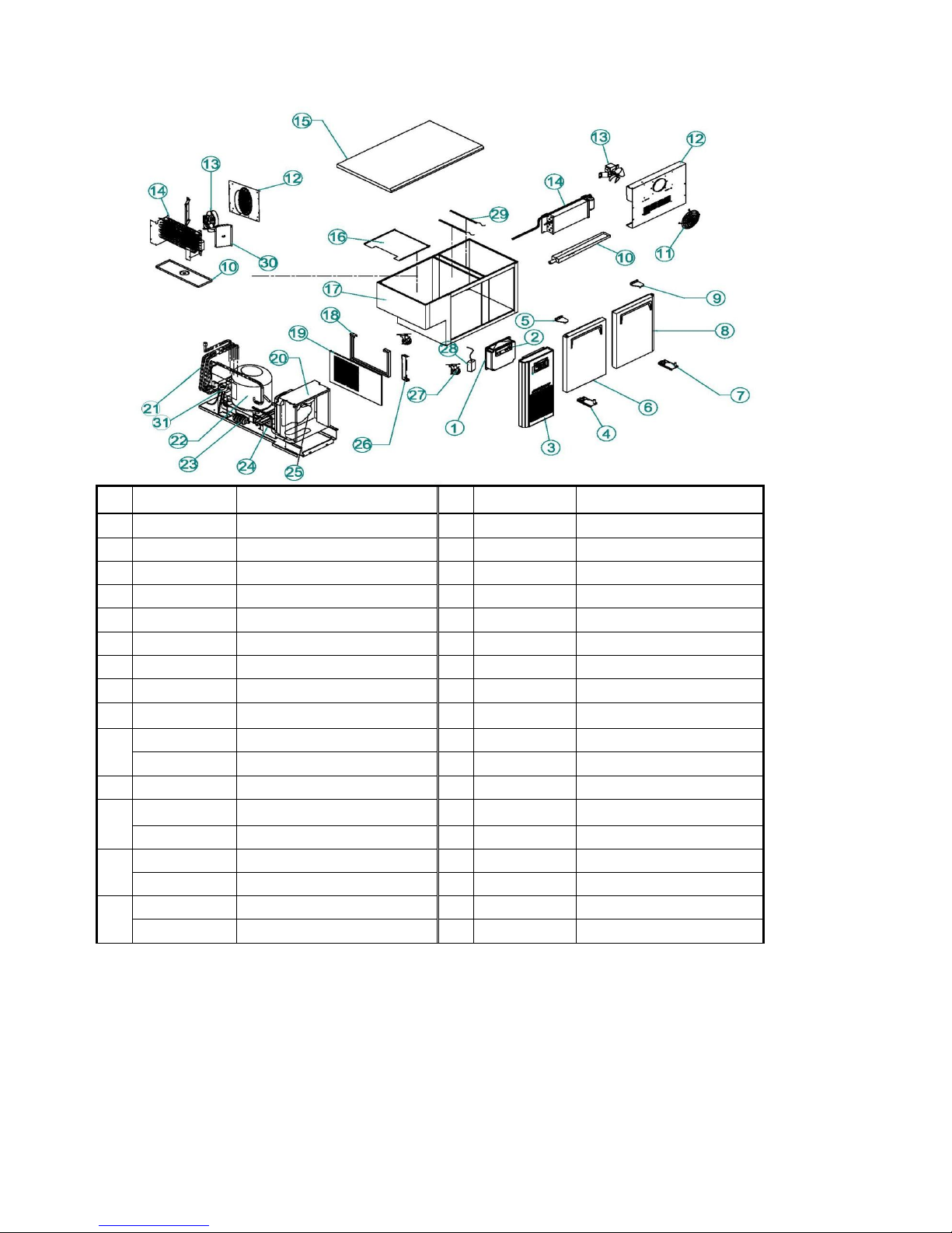
3-1-9. KUR18-3/ KUF18-3/KGR18-3 Explode View
No
Part Cord
Part Name
No
Part Cord
Part Name
1
KR81410400
MAIN PCB
15
DK84400107
EVAP ASSY FRE
2
KR81410300
FRONT PCB
16
KR8FF00100
COUNTER TOP
3
KR81410704
UNIT FRONT COVER
17
KF85220305
EVAP FAN AIR GUIDE
4
KR89940100
BOTTOM HINGE(L)
18
KU81000100
CABINET ASSY
30229M0305
BOTTOM HINGE(L)GLASS
19
KR92100301
UNIT BRACKET
5
KR89910302
TOP HINGE(L)
20
KR81900104
UNIT SAID COVER
M722900208
TOP HINGE(L)GLASS
21
KF84900104
CONDENSER ASSY
6
KR8AF00202
DOOR(L)_1800
22
KR94200109
SUCTION PIPE(B) REF
JG8AF00105
ASS'Y GLASS DOOR L
KR74200103
SUCTION PIPE(B) FRE
7
KR89910100
BOTTOM HINGE(R)
23
G5R5700200
COMP LX125 REF
Page 18

17
30229M0405
BOTTOM HINGE(R)GLASS
COMP NEK2150GK FRE
8
KR8AF00302
DOOR_1800(M)
24
BR84100100
DRYER
JG8AF00205
ASS'Y GLASS DOOR R
25
M729300102
DRAIN PAN
9
M722900106
DOOR_1800(R)
26
G8F5000200
CONDENSER FAN MOTOR
JG8AF00205
ASS'Y GLASS DOOR R
27
KF82100208
UNIT BRACKET(A)
10
KR89910402
TOP HINGE(R)
28
K3F3200901
LEVEL FOOT&CASTER
M722900108
TOP HINGE(R)GLASS
29
KG81200100
SMPS
11
KR91800201
EVAP DRAIN GUIDE
30
KG89600102
LED LAMP
12
KR91800102
AIR GUIDE(L/R)
13
KF81700100
EVA DUCT
14
G8F5000100
EVA FAN MOTOR
15
DK8A100104
EVAP ASSY REF
3-1-10. KHR18-3/KSR18-3 Explode View
KHR18-3
Page 19

18
KSR18-3
No
Part Cord
Part Name
No
Part Cord
Part Name
1
KR81410400
MAIN PCB
16
BR8AB00100
CABINET ASSY
2
KR81410300
FRONT PCB
17
KR92100302
UNIT BRACKET
3
KR81410704
UNIT FRONT COVER
18
KR81900104
UNIT SAID COVER
4
5
KR89910100
BOTTOM HINGE(R)
19
KF24900105
CONDENSER ASSY REF
KR8AF00102
DOOR(R)_1200
KF84900105
CONDENSER ASSY FRE
6
7
KR89910402
TOP HINGE(R)
20
BR84200105
SUCTION PIPE(B) 18
U609000103
FAN COVER
21
G2R5700200
COMP REF LX110 REF
8
BR81H00100
EVA DUCT KHR
G5R5700200
COMP FRE LX125 FRE
BR81700106
EVA DUCT KSR
22
BR84100100
FILTER DRYER
9
CM25000101
EVA FAN MOTOR
23
24
M729300102
DRAIN PAN
10
BR8AD00103
EVAP-ASSY
G8F5000200
CONDENSER FAN OTOR
11
BR81900103
EVA DRAIN GUIDE
25
KF82100208
UNIT SIDE BRACKET(A)
12
S722500104
PAN GUIDE
26
K3F3200901
LEVEL FOOT&CASTER
BR81800400
PAN GUIDE
27
KR89940100
BOTTOM HINGE(L)
13
BR81800301
PAN GUIDE
28
KR8AF00202
DOOR(L)_1800
14
BS80900100
PAN SUPPORTER KHR
29
KR89910302
TOP HINGE(L)
BR81800200
PAN SUPPORTER KSR
30
KR8AF00302
DOOR(M)_1800
15
BS8FE00100
COUNTER TOP KHR
31
S488900302
HOOD LID
S728900302
HOOD LID
BR8FF00100
COUNTER TOP KSR
32
S485600202
HOOD
S725600501
HOOD
Page 20

19
3-1-11. KURF18-3Explode View
No
Part Cord
Part Name
No
Part Cord
Part Name
1
KRF2500700
MAIN PCB
16
KF85220305
EVAP FAN AIR GUIDE
2
KRF2500600
FRONT PCB
17
KRF8000100
CABINET ASSY
3
KR81410704
UNIT FRONT COVER
18
KR92100301
UNIT BRACKET
4
KR89940100
BOTTOM HINGE(L)
19
KR81900104
UNIT SAID COVER
5
KR89910302
TOP HINGE(L)
20
KF84900105
CONDENSER ASSY
6
KR8AF00202
DOOR(L)_1800
21
KRF2600201
SUCTION PIPE(B)
7
KR89910100
BOTTOM HINGE(R)
22 NEK2150GK
8
KR8AF00102
DOOR(R)_1800
23
BR84100100
DRYER
9
KR89910402
TOP HINGE(R)
24
M729300102
DRAIN PAN
10
BR91900101
EVA DRAIN GUIDE REF
25
G8F5000200
CONDENSER FAN MOTOR
KR91800203
EVA DRAIN GUIDE FRE
26
KF82100208
UNIT BRACKET(A)
11
U609000103
FAN COVER REF
27
K3F3200901
LEVEL FOOT&CASTER
12
KRF8100600
EVAP DUCT REF
28
KG81200100
SMPS
KF81700104
EVAP DUCT FRE
29
KG99600102
LED LAMP FRE
13
CM25000101
EVA FAN MOTOR REF
KG59600102
LED LAMP REF
G8F5000100
EVA FAN MOTOR FRE
30
KR91800102
AIR GUIDE(L/R)
14
KRF1822100
EVAP ASSY REF
31
K1D6900100
STRING MOTOR
DK9AI00104
EVAP ASSY FRE
32
KR8AF00302
DOOR(M)_1800
15
KR8FF00100
COUNTER TOP
Page 21

20
3-2. Wiring Diagram
3-2-1 (KUR 9-1, KUR12-2, KUR15-2, KUR18-3 KGR 9-1, KGR12-2, KGR15-2, KGR18-3)
3-2-2. Wiring Diagram (KUF 9-1, KUF12-2, KUF15-2, KUF18-3)
Page 22

21
3-2-3. Wiring Diagram (KHR 9-1, KHR12-2, KHR15-2, KHR18-3 KSR 9-1, KSR12-2, KSR15-2, KSR18-3)
3-2-4. Wiring Diagram ( KURF12-2, KURF15-2, KURF18-3)
Page 23

22
3-4. PCB Control Instruction
3-3-1. Basic Operation
1) Plug in and the Display panel will be lighted and make a beep sound.
The compressor will begin to run.
2) The compressor is automatically cycled by the electronic controller (PCB).
3) The Defrost cycle is automatically controlled by the PCB.
4) Good Air Flow in refrigerator unit is critical.
Be careful to load product so that it neither presses against the back wall, nor reaches within four inches
from the evaporator compartment.
5) When the inside temperature is lower than -45℃, the panel will display “LO”.
6)Higher than +18℃, the panel will display “HI”.
1. By pushing the up/down button, you can set the
inside temperature.
2. If you want lower temperature, push the Down
1. If you push the MEAT button, the unit keeps meats
and fishes freshly.
2. Push the MEAT button again, the function will
cancel.
3. There is a lack of MEAT button on KSR / KHR KUF
series
Page 24

23
3-4. PCB Function Manual
3-4-1.How to set up manual defrost
Cancel the frosting function of evaporator.
STEP
OPERATION
DISPLAY
RESULT
Step 1
Push the ▼ ▲ button Five seconds.
Step 2
Push the ▼button once
Step 3
Push the ▼button once
Start manual defrost
The shortest defrosting time is twenty minutes, the longest defrosting time is 40 minutes.
3-4-2. How to remove the manual defrosting
STEP
OPERATION
DISPLAY
RESULT
Step 1
Push the ▼ ▲ button Five seconds.
Step 2
Push the ▼button once
Step 3
Push the ▼button once
It will indicated the current
inner temperature.
1. By pushing the up/down button, you can set the
inside temperature, temperature will be displayed.
1. After PCB setting ,bar LED show the unit inside
temperatue
Page 25

24
3-4-3. How to set up the correction of inside temperature
STEP
OPERATION
DISPLAY
RESULT
Step 1
Push the ▼ ▲ button Five seconds.
Step 2
Push the ▼button twice time.
Now is the setting value.
Step 3
Push the ▲ button When changed
Setting
value
Reference Table1
Table 1
Display
Description
Display
Description
Memo
"00"
unchangeable
" 50"
5.0℃ ↑
"- 5"
0.5℃ ↓
" 45"
4.5℃ ↑
"-10"
1.0℃ ↓
" 40"
4.0℃ ↑
"-15"
1.5℃ ↓
" 35"
3.5℃ ↑
"-20"
2.0℃ ↓
" 30"
3.0℃ ↑
"-25"
2.5℃ ↓
" 25"
2.5℃ ↑
"-30"
3.0℃ ↓
" 20"
2.0℃ ↑
"-35"
3.5℃ ↓
" 15"
1.5℃ ↑
"-40"
4.0℃ ↓
" 10"
1.0℃ ↑
"-45"
4.5℃ ↓
" 5"
0.5℃ ↑
"-50"
5.0℃ ↓
"00"
Non
3-4-4. Correction Temperature on Display PCB
STEP
OPERATION
DISPLAY
RESULT
Step 1
Push the ▼ ▲ button Five seconds.
Step 2
Push the ▼button two time.
Step 3
Push the ▼button four time.
OF->Od->dF->dt->CA
Revised
Now is the setting value.
Step 3
Push the ▲ button When changed
Setting
value
Reference Table 2
Page 26

25
Table 2
Display
Description
Display
Description
Memo
"00"
unchangeable
" 50"
5.0℃ ↑
"-10"
1.0℃ ↓
" 40"
4.0℃ ↑
"-20"
2.0℃ ↓
" 30"
3.0℃ ↑
"-30"
3.0℃ ↓
" 20"
2.0℃ ↑
"-40"
4.0℃ ↓
" 10"
1.0℃ ↑
"-50"
5.0℃ ↓
"00"
Non
3-4-5. Change Model
STEP
OPERATION
DISPLAY
RESULT
Step 1
Push the ▼ ▲ button Five seconds.
Step 2
Push the ▼button fivetime.
Now is the setting value.
Step 3
Push the ▼ button When changed
Setting
value
Reference Table 3
Table 3
Display
Description
applicable Model
“0” R KUR Series
“1” F KUF Series
“2”
RF
K-Series Dual
“3”
constant temperature
K-Series constant temperature
3-4-6. Change the defrost cycle
STEP
OPERATION
DISPLAY
RESULT
Step 1
Push the ▼ ▲ button Five seconds.
Step 2
Push the ▼button twotime.
Step 3
Push the ▼button twotime.
OF->Od->dF modified
Now is the setting value.
Step 4
Push the ▲ button When changed
Setting
value
Reference Table 4
Page 27

26
Table 4
Freezer Model
Ref Model
Changeable from 4 to 12 hours
Changeable from 4 to 60 hours
Default "6"
Default "10"
3-4-7. Change the deforst temperature
STEP
OPERATION
DISPLAY
RESULT
Step 1
Push the ▼ ▲ button Five seconds.
Step 2
Push the ▼button twotime.
Step 3
Push the ▼button threetime.
OF->Od->dF->dt modified
Now is the setting value.
Step 4
Push the ▲ button When changed
Setting
value
Reference Table 5
Table 5
Freezer Model
Ref Model
Changeable from 0 to20℃
Changeable from 0 to20℃
Default "10"
Default "8"
3-4-8. Change Temperature showing method
STEP
OPERATION
DISPLAY
RESULT
Step 1
Push the ▼ ▲ button Five seconds.
Step 2
Push the ▼button sixtime.
Now is the setting value.
Step 3
Push the ▼ button When changed
Setting value
Reference Table 6
Table 6
Setting value
description
Memo
℃
Set up ℃ temp
℉
Set up ℉ temp
Page 28

27
3-4-9. Control Eva fan motor
STEP
OPERATION
DISPLAY
RESULT
Step 1
Push the ▼ ▲ button Five seconds.
Step 2
Push the ▼button ninetime.
Now is the setting value.
Step 3
Push the ▼ button When changed
Setting value
Reference Table 7
Table 7
Setting value
description
Memo
“o”
Eva motor is running with setting mode on Comp Off
“n”
Eva motor is keeping running even if Comp Off
3-4-10. Verify Error Code
STEP
OPERATION
DISPLAY
RESULT
Step 1
Push the ▼ ▲ button Five seconds.
Step 2
Push the ▼button fourtime.
If Bar LED will not display error,
it will indicate no
Step 3
Push the ▼ button When changed
Error value
If there are lots of error, bar
LED will display error sequently.
☞ Verify Error Code
No
Function
Display
Malfunction description
Memo
1
F-SENSOR
- When sensor is short, or the temperature is above
65℃
ERROR
running
- When sensor is open, or the temperature is lesser
than -50℃.
2
D1-SENSOR
- When sensor is short, or the temperature is above
65℃
Normal
running
- When sensor is open, or the temperature is lesser
than -50℃.
3
RT-SENSOR
(outer sensor)
- When sensor is short, or the temperature is above
65℃
Normal
running
- When sensor is open, or the temperature is lesser
than -50℃.
4
defrost 1
ERROR
- (defrost 1) It will automatically stop after 80 minutes.
Normal
running
Page 29

28
5
E²ROM ERROR
- E²ROM 이 read 및 write 가되지
않는 경우
Normal
running
6
Refrigerator
defrosting
ERROR
- When the refrigerator defrost 40 minutes, it will
automatically stop.
Normal
running
7
Cycle ERROR
- The COMP continuously run 30 minutes.
The temperature of D-SENSOR doesn’t reach 0℃
Normal
running
(freezer)
3-5. PCB function instructionDry –type model ( REF / FRE)
Model
Sensor
Compressor
HTR
Front PCB
Memo
R-
Sensor
D-Sensor
1Comp
2Comp
R/F
DUAL
KUR/F 9-1
O O O
O O
KGR9-1
KUR/F12-2
O O O
O O
KGR12-2
KUR/F15-2
O O O
O O
KGR15-2
KUR/F18-3
O O O
O O
KGR18-3
KHR9-1
O O O
O
O
KGR9-1
KHR12-2
O O O
O
O
KSR12-2
KHR15-2
O O O
O
O
KSR15-2
KHR18-3
O O O
O
O
KSR18-3
3-6. COMPRESSOR running、starting、stopping
3-6-1. COMP running
- COMP will stop for 4 minutes. (When the comp stopped, comp will be banned running during the
4 minutes.)
Page 30

29
Section 4 Replacement Of Main Components
4-1. Mullion Heater replacement
A. Unscrew the four screws from mullion .
B. Disconnect the connectors from Mullion Heater top.
C. Take apart mullion front cover from mullion.
D. Pull out the heater from the inlet.
Page 31

30
E. Reinstall the new mullion heater, do reversed in order.
F. Seal gaps with silicon after installation.
4-2. Cabinet Heater replacement
A. Disassemble Unit Front Cover.
B. Disconnect housing connector.
.
Page 32

31
C. Unscrew the top hinge.
D. Lift the door and pull out the door.
E. Insert the and edge of “-“type screw driver into the gap between the frame and frame cover, take apart the
frame.
Pull out the heater from the inlet.
F. Insert new cabinet heater to the inlet.
Page 33

32
4-3. Refrigeration compartment replacement
A. Disassemble Unit Front Cover..
B. Unscrew unit Side Cover.
C. Unscrew the comp base.
D. ull out the condensing unit.
Page 34

33
E. Refrigeration compartment
4-4.Remove Counter Top
A.Unscrew the cabinet Reinforce.
B.Unscrew the counter top bracket(Right).
C.Unscrew the counter top bracket(Left).
Page 35

34
D. Cut the counter top out of cabinet as below.
4-5.Remove Evap Motor
A. Disassemble counter top and do as below.
B. Unscrew evap cover.
Take apart Evap Motor Housing.
Page 36

35
Unscrew Evap Motor Bracket.
Remove Evap.
4-6.Remove Evaporator
Disassemble Counter Top and Evap Motor, then do as below.
Unscrew Air Guide, disconnect sensor connector, take apart Air Guide.
- Reforgerator
Page 37

36
- Freezer
.
Section 5 Customer Support
5-1. MAIN COMPONENTS
5-1-1.COMPRESSOR
MODEL
PART NAME
PART NO.
HP
TYPE OF
INPUT
REFRIGERAN
T
KUR/KGR9-1 / 12-2 / 15-2
LX110LAJM
G2R5700200
1/4HP
RSCR
220V 50Hz
R-134a
KUR / KGR18-3
LX125LAJM
G5R5700200
1/3HP
RSCR
220V 50Hz
R-134a
KUF9-1 / 12-2 / 15-2
LX125LAJM
G5R5700200
1/3HP
RSCR
220V 50Hz
R-134a
KUF18-3
NEK2150GK
K3F5700200
3/4HP
CSIR
220V 50Hz
R-404a
KHR/KSR9-1 / 12-2 / 15-2
LX110LAJM
G2R5700200
1/4HP
RSCR
220V 50Hz
R-134a
KHR/KSR18-3
LX125LAJM
G5R5700200
1/3HP
RSCR
220V 50Hz
R-134a
KURF12-2
LX125LAJM
G5R5700200
1/3HP
RSCR
220V 50Hz
R-134a
KURF15-2/KURF18-3
NEK2150GK
K3F5700200
3/4HP
CSIR
220V 50Hz
R-404a
5-1-2.COMPRESSOR RELAY, OVERLOAD
MODEL
RELAY
OVERLOAD
NOTE
KUR/KGR9-1 / 12-2 / 15-2
P470MD/47±20$Ω
4TM314TFB
KUR / KGR18-3
P470MD/47±20$Ω
4TM412RFB
KUF9-1 / 12-2 / 15-2
P470MD/47±20$Ω
4TM314TFB
KUF18-3
0012-65 248 2334112
T06341G6
KHR/KSR9-1 / 12-2 / 15-2
P470MD/47±20$Ω
4TM314TFB
KHR/KSR18-3
P470MD/47±20$Ω
4TM412RFB
KURF12-2
P470MD/47±20$Ω
4TM314TFB
KURF15-2/KURF18-3
0012-65 248 2334112
T06341G6
Page 38

37
5-1-3.COMPRESSOR CAPACITOR
MODEL
STARTING
RUNNING
MAKER
NOTE
KUR/KGR9-1 / 12-2 / 15-2
-
400V/5 ㎌
- - KUR / KGR18-3
-
400V/5 ㎌
- - KUF9-1 / 12-2 / 15-2
-
400V/5 ㎌
- - KUF18-3
330V/72~88чF
-
-
KHR/KSR9-1 / 12-2 / 15-2
-
400V/5 ㎌
-
-
KHR/KSR18-3
-
400V/5 ㎌
- - KURF12-2
-
- - KURF15-2/KURF18-3
330V/72~88чF
400V/5 ㎌
-
-
5-1-4.CONDENSER FAN MOTOR
MODEL
PART NAME
PART NO.
POLE
INPUT
TYPE
BLADE
MAKER
KUR/KGR9-1 / 12-2 / 15-2
IS-4420QTBC
G8F5000200
4P
220V,5
0Hz
SHADED
POLE
INDUCTIO
N
AL3
KUR / KGR18-3
KUF9-1 / 12-2 / 15-2
KUF18-3
KHR/KSR9-1 / 12-2 / 15-2
KHR/KSR18-3
KURF12-2
KURF15-2/KURF18-3
5-1-5.EVAPORATOR FAN MOTOR
MODEL
PART NAME
PART NO.
POLE
INPUT
TYPE
BLADE
MAKE
R
KUR/KGR9-1 / 12-2 / 15-2
IS-4420QTBD
G8F5000100
4P
220V,50Hz
SHADE
D
POLE
INDUC
TION
AL4
-
KUR / KGR18-3
KUF9-1 / 12-2 / 15-2
KUF18-3
KHR/KSR9-1 / 12-2 / 15-2
IS-27213QTBE
CM25000101
2P
KHR/KSR18-3
KURF12-2 / KURF15-2
IS-4420QTBD
G8F5000100
4P
KURF18-3
IS-27213QTBE
CM25000101
2P
PA-66 4
Page 39

38
5-2. Filter Dryer
MODEL
PART NO.
REFRIFERANT
SPEC
NOTE
KUR/KGR9-1 / 12-2 / 15-2
BR84100101
R-134a
C-052-5
-
KUR / KGR18-3
KUF9-1 / 12-2 / 15-2
KUF18-3
KHR/KSR9-1 / 12-2 / 15-2
KHR/KSR18-3
KURF12-2
KURF15-2/KURF18-3
5-3. Defrost Heater
MODEL
PART NO.
SPEC
NOTE
KUF9-1
KF95300101
220V 300W
KUF12-2/15-2/18-3
KF25300101
220V 450W
KURF12-2/15-2/18-3
KF95300101
220V 300W
5-4. Thermal Fuse
MODEL
PART NO.
SPEC
NOTE
KUF9-1 / 12-2
UF46200100
N50
KUF15-2/18-3
G8F6200500
N77
KURF12-2 / 15-2
UF46200100
N50
KURF18-3
G8F6200500
N77
Page 40

39
5-5. Capillary Tube Spec
Model
Suction Pipe A
Suction Pipe B
Tube I.D
Length
Tube I.D
Length
KUR9-1 KGR9-1
Ф2.4XФ1.2
600mm
Ф2.4XФ1.2
2500mm
KUR12-2 KGR12-2
Ф2.4XФ1.2
600mm
Ф2.4XФ1.2
2500mm
KUR15-2 KGR15-2
Ф2.4XФ1.2
600mm
Ф2.4XФ1.2
2500mm
KUR18-3 KGR18-3
Ф2.4XФ1.2
600mm
Ф2.4XФ1.2
3000mm
KUF9-1
Ф2.4XФ1.2
600mm
Ф2.4XФ1.2
3000mm
KUF12-2
Ф2.4XФ1.2
600mm
Ф2.4XФ1.2
3000mm
KUF15-2
Ф2.4XФ1.2
600mm
Ф2.4XФ1.2
3000mm
KUF18-3
Ф2.4XФ1.2
600mm
Ф2.4XФ1.2
3400mm
KHR9-1 KSR9-1
Ф2.4XФ1.2
530mm
Ф2.4XФ1.2
2000mm
KHR12-2 KSR12-2
Ф2.4XФ1.2
530mm
Ф2.4XФ1.2
2500mm
KHR15-2 KSR15-2
Ф2.4XФ1.2
530mm
Ф2.4XФ1.2
2500mm
KHR18-3 KSR18-3
Ф2.4XФ1.2
530mm
Ф2.4XФ1.2
3000mm
Model
Suction Pipe A
Suction Pipe B
Tube I.D
Length
Tube I.D
Length
KURF12-2
Ф2.4XФ1.2
1650mm
600mm
Ф2.4XФ1.2
850mm
3500mm
KURF15-2
Ф2.4XФ1.2
1650mm
600mm
Ф2.4XФ1.2
850mm
3500mm
KURF18-3
Ф2.4XФ1.2
1650mm
600mm
Ф2.4XФ1.2
850mm
3500mm
5-6. The cycle pressure of model starting (refrigerant weight)
MODEL
COMP model
refrigerant
High
pressure(Psi)
Low
pressure(Psi)
Memo
refrigerant
Refrigerant charge
KUR9-1
LX110LAJM
R134a
240gr
KUR12-2
LX110LAJM
R134a
240gr
125 6
KUR15-2
LX110LAJM
R134a
240gr
KUR18-3
LX125LAJM
R134a
340gr
110 5
KGR9-1
LX110LAJM
R134a
240gr
KGR12-2
LX110LAJM
R134a
240gr
125 6
KGR15-2
LX110LAJM
R134a
240gr
KGR18-3
LX125LAJM
R134a
340gr
110 5
KUF9-1
LX125LAJM
R134a
330gr
KUF12-2
LX125LAJM
R134a
380gr
KUF15-2
LX125LAJM
R134a
380gr
KUF18-3
NEK2150GK
R404a
370gr
KHR9-1
LX110LAJM
R134a
240gr
Page 41

40
KHR12-2
LX110LAJM
R134a
240gr
125 6
KHR15-2
LX110LAJM
R134a
240gr
KHR18-3
LX125LAJM
R134a
300gr
110 5
KSR9-1
LX110LAJM
R134a
240gr
KSR12-2
LX110LAJM
R134a
240gr
125 6
KSR15-2
LX110LAJM
R134a
240gr
KSR18-3
LX125LAJM
R134a
300gr
110 5
KURF12-2
LX125LAJM
R134a
290gr
KURF15-2
NEK2150GK
R404a
310gr
KURF18-3
NEK2150GK
R404a
320gr
 Loading...