

Page 1

Commercial
Refrigerator&Freezer
Service Manual
Solid Door J series
Model No.:
JRF-45-2
Page 2

TABLE OF CONTENTS
1.FEATURE CHART
1-1. FRONT VIEW/PLAN VIEW:JRF45-2
2.WIRING DIAGRAM
2-1. JRF-45-2
3.PART DETAIL
3-1. TOP GRILLE
3-2. REFRIGERA TION COMPARTMENT
3-3. CONTROL BOX
3-4. DOOR
3-5. COOLING COMPARTMENT
4 .MAIN COMPONENTS
5. ELECTRONIC CONTROLLER INSTRUCTION
6. PARTS LIST
7. REPLACEMENT OF MAIN COMPONENTS
7-1. TOP GRILLE PART
7-2. REPLACE DOOR
7-3. REFRIGERATION COMPARTMENT’S PART.
7-3-1.
REPLACE DUCT AND LAMP
7-3-2 . REPLACE T SENSOR AND D SENSOR
7-3-3. REPLACE THE EVAPORATOR COIL AND F-SENSER
7-3-4.REPLACE THE DEFROST HEATER (FREEZER ONLY)
7-3-5. REPLACE THE EVAPORATOR FAN MOTOR AND FAN BLADE
7-4.
CONTROL BOX PART
CONDENSER UNIT
7-5.
7-6. REPLACE TH E C A BINET HEAT ER AND MULLION HEATER
Page 3
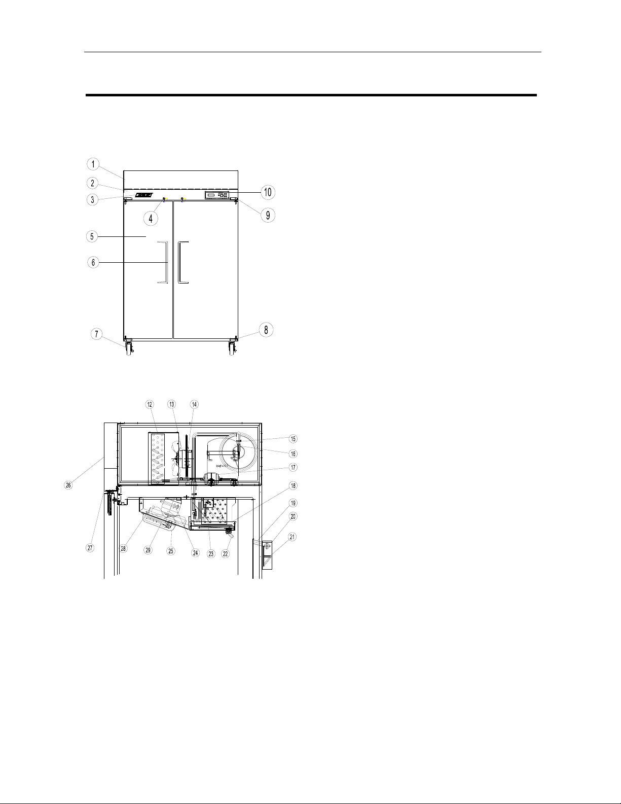
1. FEATURE CHART
1.1. FRONT VIEW/PLAN VIEW
1 TOP GRILLE(T)
2 TOP GRILLE(B)
3 MASCOT
4 KEY
REFRIGERATOR MANUFACTURER
7 CASTER
5 ASS’Y DOOR(L)
6 DOOR HANDLE
8 BOTTOM HINGE(R)
9 TOP HINGE(R)
10 PANEL FRONT PCB
12 CONDENSER
13 CONDENSER MOTOR
14 MOTOR BRACKET
15 SUCTION PIPE
16. COMPRESSER
17. DRYER
18 DRAIN P A N
19. DRAIN GUIDE
20 DRAIN CASE
21 DRAIN PIPE
22 DRAIN CONNECTOR
23 EVAPORATOR
24EVAPORATOR MOTOR
25 LAMP COVER
26 TOP GRILE T
27TOP GRILE B
1
Page 4
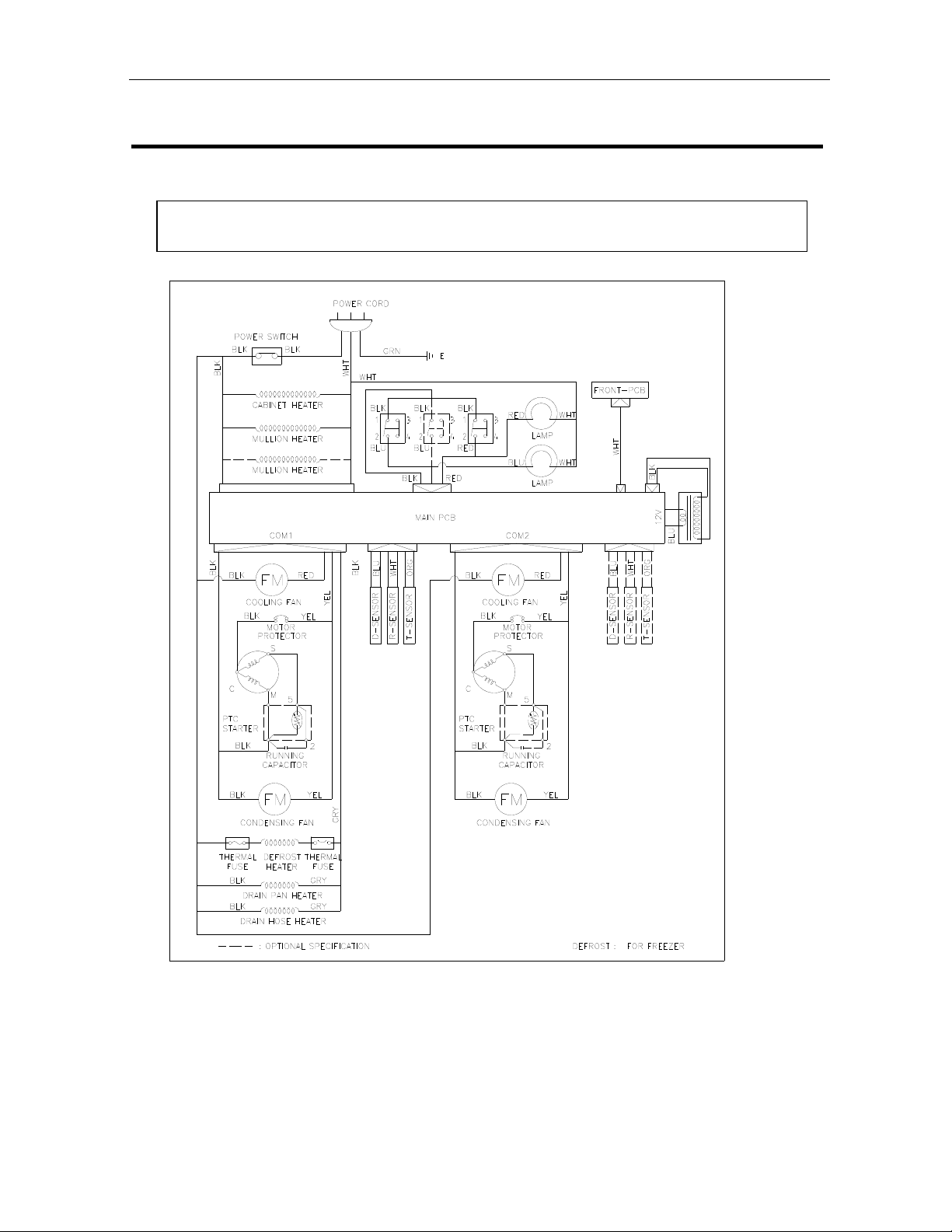
2. WIRING DIAGRAMS
2-1.
WIRING DIGRAM
2
Page 5
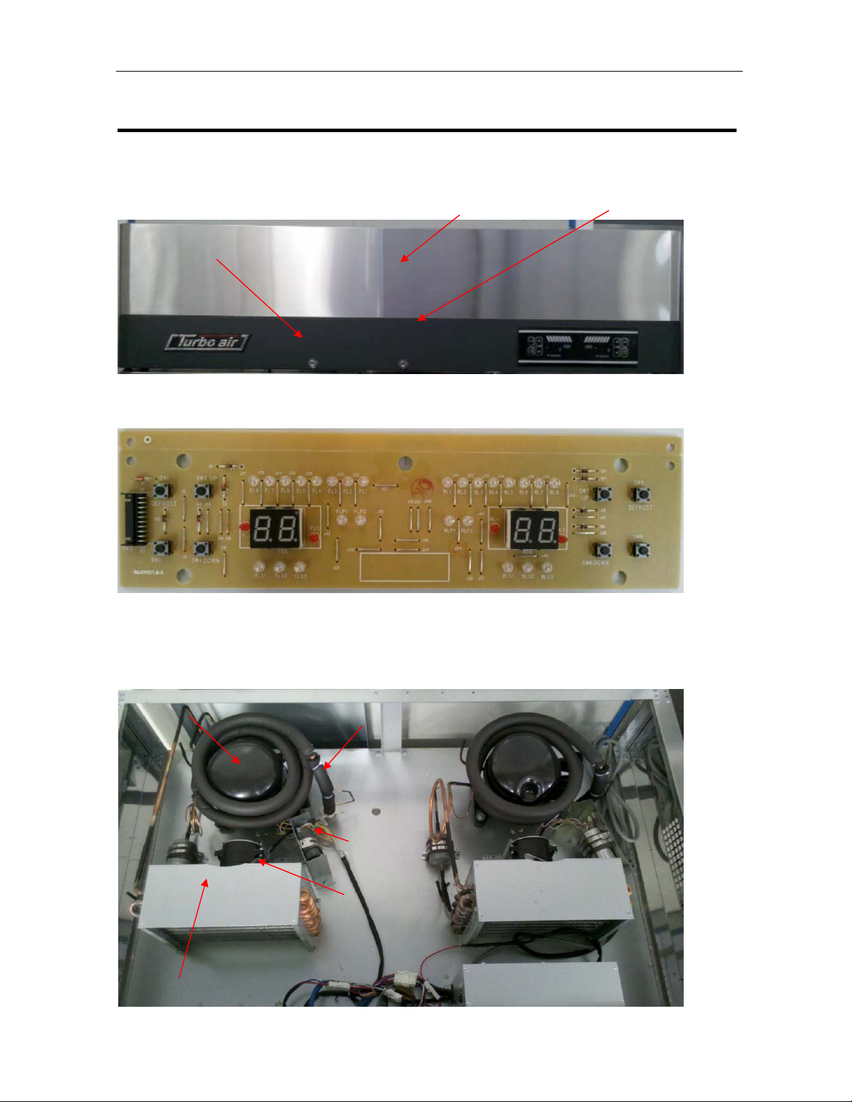
3.PART DETAIL
3-1. TOP GRILLE
Top grille(T), top grille (B)
Top grille (B)
Front pcb
Key Top grille (T)
3-2. Refrigeration Compartment
Cycle Assembly
COMPRESSOR
DRYER
SUCTION PIPE(A)
capacitance
CONDENSER FAN
BLADE
CONDENSER
3
Page 6
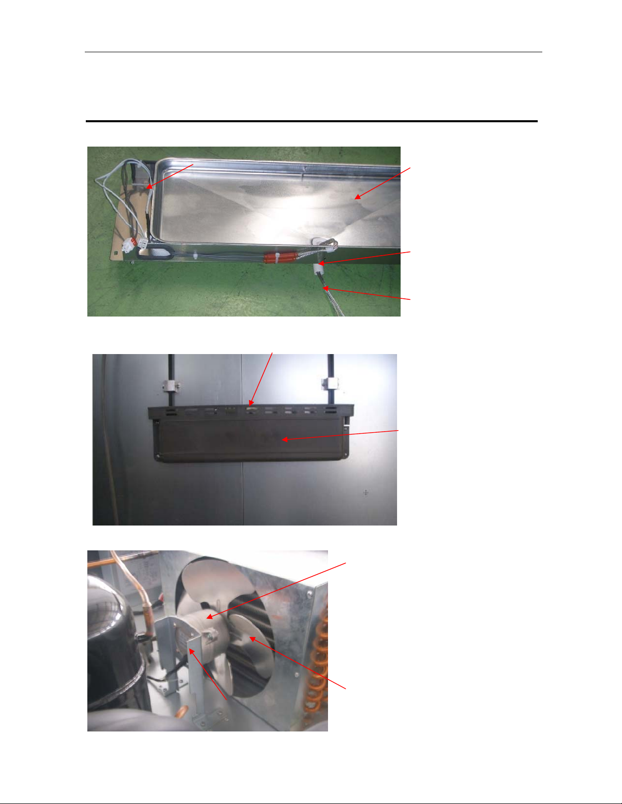
PART DETAIL
Drain Pan Assembly
DRAIN PAN HEATER
DRAIN PAN
CONNECTOR
DRAIN HOSE
DRAIN HOSE HEATER
Drain Case Assembly
DRAIN HOSE
DRAIN CASE
Condenser Fan Motor Assembly
CONDENSER MOTOR BRACKET
CONDENSER MOTOR
CONDENSER FAN BLADE
4
Page 7
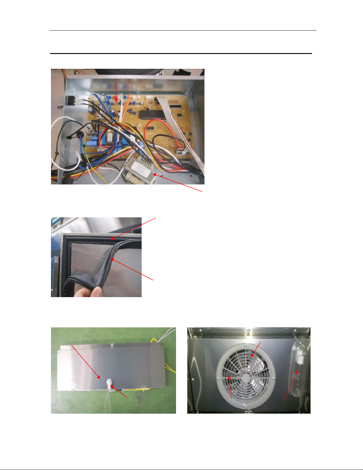
3-3. CONTROL BOX
MAIN PCB
3-4. Door
Gesket
FRAME DOOR
TRANSFORMER
部件介绍
3-5.EVAP HOUSING
Freezer Duct & Refrigerator Duct
Evap housing cover(b)
Drain connector(b)
DOOR GASKET
Evap housing cover(f)
Evap fan cover
5
Lamp&lamp cover
Page 8
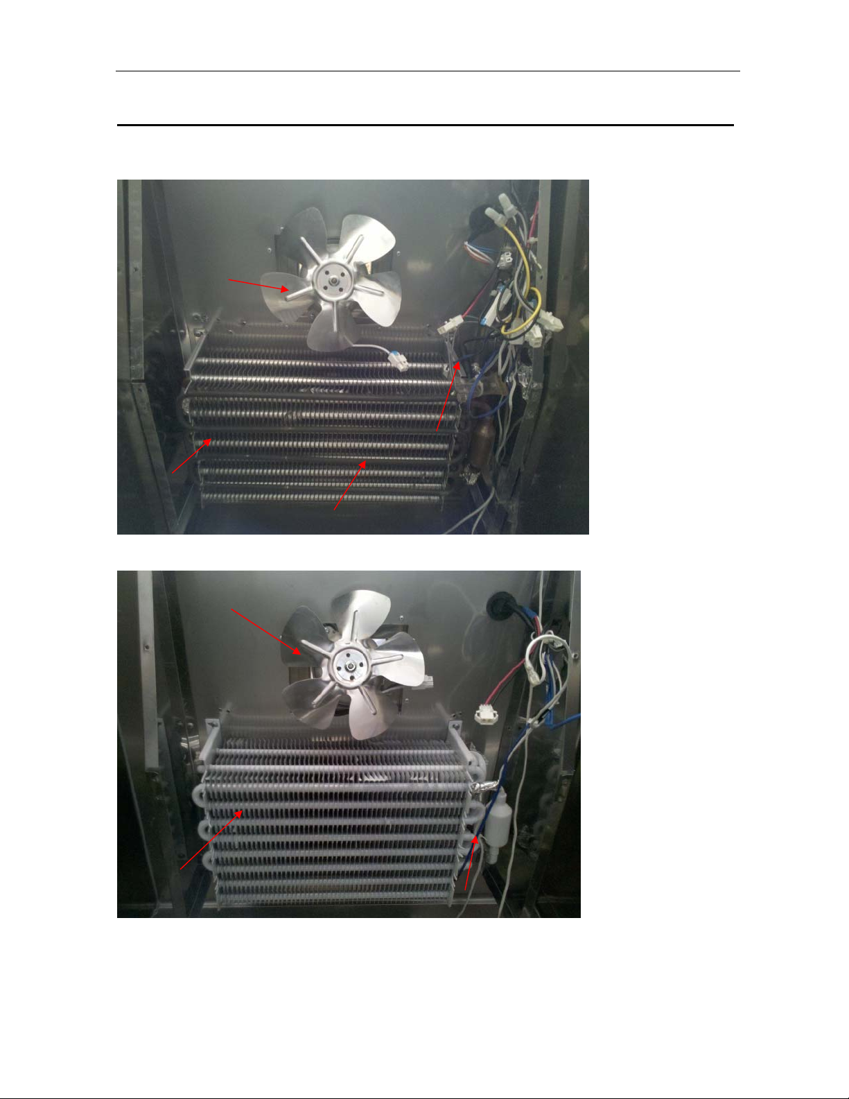
PART DETAIL
Freezer EVAP.,Fan
evap fan blade
D-sensor
evap
Defrost heater
Refrigerator evap. Fan.
EVAP FAN BLADE
EVAP
D-SENSOR
6
Page 9

MAIN COMPONENTS
4-1. COMPRESSOR
model
refrigerant
Voltage
Comp. model
Part code
Starting Type
JRF-45-2
R134a R134a
115v 115v
HBL27YE-1 SK1A1C-L2W
M369700100 M609700100
220v/100μF 125v/125μF
4-2. COMPRESSOR RELAY
Model
Voltage
Relay
Model
JRF-45-2
115v/60HZ
783RHBZZ-52
795TFBZZ-53
4-3. CONDENSER DRYER
Model
Refrigerant
Spec.
Part code
JRF-45-2
R-134a
C-052-S
M726800100
4-4. CAPACITOR
Model
Voltage
Running
Part code
Starting
Part code
JRF-45-2
115V/60HZ
15V/60HZ
200V/100uf
200V/10 ㎌
4-5. EVA FAN MOTOR
Model
Voltage
Motor
Model.
Part
code
JRF-45-2
120V/60Hz
IS4420ODWSN-2A
P8F6600100
7
Page 10

MAIN COMPONENTS
4-6. CONDENSOR FAN MOTOR
MODEL
Voltage
Motor
Model
Part code
JRF-45-2
115V,60Hz
IS4420DWSG-1
G8F6600100
4-7. EVA DEFROST HEATER
Model
Voltage
Spec
Part code
JRF-45-2
115V
280W
K2D5301001
4-8. LAMP
Model
Voltage
Spec.
Part code
JRF-45-2
120V/40W
P996300100
4-9. TRANSFORMER
Model
Voltage
Spec.
Part code
JRF-45-2
115V/60Hz
P996000100
4-10.MAIN PCB
Model
Voltage
Spec..
Part code K3F5401300
JRF-45-2
115v
8
Page 11

5.ELECTRONIC CONTROLLER INSTRUTION
5-1. HOW TO USE THE PANEL
9
Page 12

K-series part list
Part Code Part Name D H L Material JRF-45-2
K3F1901100 AIR DUCT 0.4 576.5 547.4 GI 1
K3F2900800 BOTTOM HINGE(L) 0 1
K3F2900900 BOTTOM HINGE(R) 0 1
T5R5300102 CABINET HEATER SILICON&편조 1
K3F1900500 CABINET SIDE Fixture (M) 2 264.2 82.1 GI 2
K2F1900300 CABINET SIDE Fixture (T) 2 1209 54 GI 2
K3F1101700 CABINET SIDE PANEL (T)(L) 0.6 852.4 338 AL 1
K3F1100901 CABINET SIDE PANEL (T)(R) 0.6 852.4 338 AL 1
K3F6500400 CASTER 0 2
K3F6500200 CASTER - 2
M369700100 COMPRESSOR 0 HBL27YE-1 1
M609700100 COMPRESSOR 0 SK1A1C-L2W 1
M724100100 CONDENSER MOTOR BRACKET 0 GI 2
K3F2000300 MOTOR FIXTURE BRACKET SUS304-2B 2
M721200200 CORD CLIP - 10
K3F5102001 D SENSOR - 2
G8F9900101 DEFROST FIXTURE SPRING SUS304 12
K2D5301001 DEFROST HEATER SUS304 1
K3F1900400 DISPLAY PCB BACK COVER 0.4 260 126.4 GI 1
K3D7800500 DISPLAY PCB FILM 1
G8F0501800 DOOR BUSHING NY66 2
T8F0500700 DOOR BUSHING NY66 2
K3F1501500 DOOR FIXTURE BRACKET 2 150.2 70 GI 2
K2D3300200 DOOR GASKET 688 1441.5 PVC 난연 1
K2D3103000 DOOR GASKET 518 1445 PVC 난연 1
G993200104 DOOR HANDLE ABS 2
K2D1500800 DOOR INNER PANEL 0.6 666.3 1430.8 AL 1
K2D1500700 DOOR INNER PANEL 0.6 486.3 1430.8 AL 1
K2D1500200 DOOR PANEL (R) 0.6 1577 808.4 SUS439-#4 1
K2D1500100 DOOR PANEL (L) 0.6 833.4 628.43 SUS439-#4 1
K3F1501400 DOOR SPACE 0.6 30 80 SUS304-#4 4
B1R0500600 DOOR STOPER (B) 0 SUS304-2B 2
B1R0500300 DOOR STOPPER BRACKET 0 0 0 PO 2
G8F3200601 DRAIN CONNECTOR A NY66 2
G8F3200700 DRAIN CONNECTOR B NY66 2
K3F7300100 DRAIN GUDIE PAD F-PS 2
K3F2500100 DRAIN GUIDE AL 2
K3F2500300 DRAIN HOSE CAP 0 2
K3F1901200 DRAIN HOSE GUIDE 0.4 165.8 370 GI 1
T8F5300800 DRAIN HOSE HEATER 0 1
10
Page 13

K3F8400500 DRAIN HOSE TIE 0 0 4
K3F5301100 DRAIN PAN HEATER AL & SILICON 1
K2R4200301 DRAIN PIPE 0 0 CU 1
M724400601 DRYER DISCHARGE CU 4
G2F4201000 DRYER DISCHARGE PIPE 0 CU 4
G8F1400200 DRYER FIXTURE BEND 0.5 24 180 SUS439-2B 2
K3F4400203 EVAP COIL CU 1
K3F4400402 EVAP COIL CU 1
P8F2700400 FAN BLADE AL 2
M722700400 FAN BLADE AL 2
K3F4500201 FIN-CONDENSER CU 2
K3D5401100 FRONT PCB (DUAL) 1
K3D3200100 FRONT PCB CASE (DUAL) 1
K3F5101900 HARNESS DISPLAY PCB 1
K2D5100600 HARNESS GRILLE DOOR SWITCH 0 1
K2D5100800 HARNESS MAIN 0 0 1
K2D5100900 HARNESS MAIN(B) 0 1
P998200100 KEY - 2
G8F3200800 KEY GUIDE ABS 2
G8F6300100 LAMP 0 0 0 2
G8F3200203 LAMP COVER PC 2
P996400100 LAMP SOCKET 0 0 0 2
K3F3103300 LINER FRAME COVER(L)(R) 0 2
K2F3100300 LINER FRAME COVER(T)(U) 0 2
K3F5401300 MAIN PCB 1
G8F9200300 MAIN PCB FIXTURE NY66 7
K3F3200100 MASCOT 0 ABS 1
P8F6600100 MOTOR 0 0 0 2
G8F6600100 MOTOR 0 0 0 2
K3F2100101 MULLION FIXTURE BRACKET 66 34.04 SUS304-#4 1
MULLION FIXTURE
K3F2100800
BRACKET(UPP) 1.5 60 52.5 SUS304 1
K3F3103900 MULLION FRAME COVER(V) 0 2
T8R5300100 MULLION HEATER (VER) SILICON&편조 1
K2F1200301 MULLION OUT COVER 0.6 1402 74.8 SUS439-#4 1
K3F4200101 PIPE(COMP-CON) CU 1
K3F4201100 PIPE(COMP-DRAIN) 0 CU 1
K3F4201300 PIPE(CON-DRAIN) 0 CU 1
M604400600 PIPE(DRYER-CAPI TUBE) CU 2
P5R5800100 POWER CORD 0 0 1
30281Q0100 POWER SWITCH 1
K3F5102101 RF SENSOR 0 2
K3F8300200 SCREW 0 16
11
Page 14

K3F9900100 SCREW 0 8
P998300200 SCREW 2
P992000301 SENSOR GUARD AL 2
K2D9000101 SHELF 0 SWRM&백색 COATING 3
K2D9000201 SHELF 0 SWRM&백색 COATING 3
P993200800 SHELF CLIP PA-66 32
K3F2700103 SHELF STANDARD 0 0 8
K3F8400100 SPRING BAR 0 1418 SWRM 2
K3F3101600 SPRING BAR GUIDE PIPE 0 1385 PVC 2
B1R0500400 STOP SPRING PLATE (L) SUS304-2B 1
B1R0501100 STOP SPRING PLATE (R) SUS304-2B 1
K3F4600103 SUCTION PIPE (A) CU 1
K3F4600403 SUCTION PIPE (A) CU 1
K3F4600600 SUCTION PIPE (B) 0 CU 2
T8F6200200 THERMAL FUSE - 1
K2D1600100 TOP GRILLE (B) 0.8 1420 238.85 GI 1
K2F1600200 TOP GRILLE (T) 0.6 1425 326.73 SUS439-#4 1
K3F2100400 TOP GRILLE (T) FIXTURE 0.6 43 43 SUS439-#4 2
K3F2901000 TOP HINGE(L) 0 1
K3F2901100 TOP HINGE(R) 0 1
P996000100 TRANS FORMER 1
K3F5101800 T-SERSOR 0 2
12
Page 15

7.
REPLACEMENT OF MAIN COMPONENTS
7-1. TOP GRILLE PART
A. Unscrew the screw located on both side of top grille (t) with the top grille (t)
fixture。
B. Hold up the top grille (T).
C. Unscrew the screw located on both side of top grille (B).
13
Page 16

REPLACEMENT OF MAIN COMPONENTS
D. Unscrew the screw located on the cabinet top cover.
E. Pull out the harness display pcb and harness grille door s/w located on back of
top grille (B).
You can replace the door switch, mascot, key, front pcb and front pcb case, etc.
14
Page 17

REPLACEMENT OF MAIN COMPONENTS
7-2. REPLACE DOOR
7-2-1. A. Disassemble top grille (T) and top grille (B) as described section 7-1.
B. Unscrew the top hinge (
C. Lift the door (
。
R) and pull it out.
R).
D. Replace the door with the new one.
E. Screw the top hinge (
F. Do just like above instructions in replacing the door (L).
L). (this process is opposite to disassemble them.)
15
Page 18

REPLACEMENT OF MAIN COMPONENTS
7-3. REFRIGERATION COMPARTMENT’S PART
- Duct and Lamp
- T-sensor and D-sensor
- Evaporator coil and F-sensor
- Defrost heater (freezer only)
- Evaporator fan motor and fan blade
7-3-1. REPLACE DUCT AND LAMP
A.Disassemble the Duct.
7-3-2. REPLACE T SENSOR AND D SENSOR (T-SENSOR IS WHITE COLOR, F -SENSOR IS ORANGE
AND D-SENSOR IS BLUE)
A.Disassemble the Duct as in 7-3-1
B. Disconnect the connector and pull out the D-sensor from the evap. replace the
new one.
(D-SENSOR IS BLUE)
16
Page 19

REPLACEMENT OF MAIN COMPONENTS
C. Take off the T-sensor from the evap. replace the new one.
(T-SENSOR IS WHITE COLOR)
7-3-3. REPLACE THE EVAPORATOR COIL AND F-SENSER
A. Welding off the connection suction pipe(A) and (B).
B. Unscrew the screw located on back side of evap. housing.
C. Take off the evaporator.
17
Page 20

REPLACEMENT OF MAIN COMPONENTS
D. Disconnect the connector and Unscrew the screws located on sensor cover and
pull out the F-sensor from the evap.sensor guide, replace the new one.
7-3-4. REPLACE THE DEFROST HEATER (FREEZER ONLY)
A. After lift the evaporator up, disconnect the connectors with harness defrost
heater and disassemble the defrost fixture spring and split the hooks of the
evap..
B. Replace the new defrost heater and fix it with heater fix spring. Connect the
connectors.
*NOTE
Why is always 220 voltage detected between connectors of the evaporator defrost
heater in the main harness?
The SNUBBER (located Main PCB) holds two AC power lines simultaneously.
The SNUBBER prevents Main PCB malfunction from spar ks occurred by other electrical
component’s ON/OFF. ( SNUBBER =Spark killer)
Because of the SNUBBER, 220 voltage is always detected, bu t electrical current in this
case is very little (small Amps.).So, this electrical current is not enough to operate the
evaporator defrost heater.
18
Page 21

REPLACEMENT OF MAIN COMPONENTS
How to measure the Amps. of the evaporator defrost heater
Disconnect the connectors of the evaporator defrost heater.
Then , prepare the additional Power Source(115V/60Hz) and the Amp. Meter.
Connect the connectors of the evaporator defrost heater to the additional power source
and read amp. Value from the Amp. Meter.
。
7-3-5. REPLACE THE EVAPORATOR FAN MOTOR AND FAN BLADE
A. After lift the evaporator up, unscrew the screw which used in fixing motor
fixture.
B. Disconnect the connectors of harness motor.
Then you can replace the evaporator fan motor and fan blade.
19
Page 22

7-4. CONTROL BOX PART
- Power relay
- Transformer
- Main PCB
A. Disassemble top grille (t) as described section 7-1 A B.
B. Pull out all connectors connected with control box.
C.Unscrewthescrewslocatedonfrontofevap-housing
E.Pull out the harness main.
主要部件的更换
20
Page 23

REPLACEMENT OF MAIN COMPONENTS
F. Unscrew the screws used in fixing power relay and trans former
G. Disconnect the main PCB fixture.
Then you can replace the power relay, trans former and main pcb.
7-5. CONDENSER UNIT
- Compressor
- Condenser fan motor
- Dryer filter
- Pressure switch
The comp. Base is located on both side on the top of the cabinet by screw, and you can replace
the Compressor ,Condenser coil Condenser fan motor, ETC. on it.
21
Page 24

REPLACEMENT OF MAIN COMPONENTS
7-6. REPLACE THE CABINET HEATER AND MULLION HEA TER
A. Disassemble the liner frame cover with the and edge of ‘一’type
screwdriver.(left/right/top/bottom side)
。
B. Disconnect the cabinet heater and pull it out.
You can replace the cabinet heater with the new one.
。
C. Assembl e t h e li n er frame cover.( left/right/top/bottom side)
22
Page 25

REPLACEMENT OF MAIN COMPONENTS
D. Disassemble the mullion frame cover(v) with the and edge of ‘一’type
screwdriver.
E. Unscrew the screw located on both side of the mullion.
F. Take apart the mullion out cover(v) from the mullion, then disconnect the
harness mullion heater.
23
Page 26

REPLACEMENT OF MAIN COMPONENTS
G. Change the old mullion heater(v) and install the new one with the gap between
wires 1.2 inch.
24
 Loading...