

Page 1

Commercial
Refrigerator & Freezer
Service Manual
Solid Door J series
Model JRF-19
Page 2

TABLE OF CONTENTS
1.FEATURE CHART
1-1. FRONT VIEW/PLAN VIEW:JRF-19
2.WIRING DIAGRAM
3.PART DETAIL
3-1.TOP GRILLE
3-2.REFRIGERATION COMPARTMENT
3-3.CONTROL BOX
3-4.DOOR
3-5.COOLING COMPARTMENT
4.MAIN COMPONENTS
5.ELECTRONIC CONTROLLER INSTRUCTION
6.PARTS LIST
7.REPLACEMENT OF MAIN COMPONENTS
Page 3
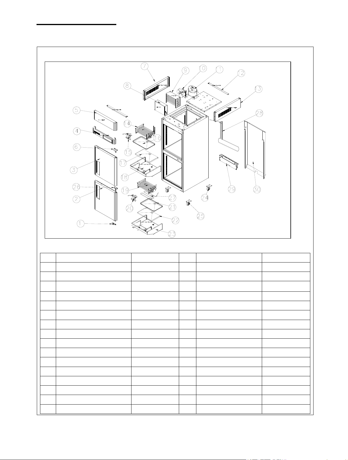
1.FEATURE CHART
MODEL :JRF-19
◎Part Name
NO PARTNAME PART CORD NO PARTNAME PART CORD
1 BOTTOM HINGE(R) K3F2901701 17 DRAIN GUIDE PAD K3F7300103
2 ASS'Y DOOR(UR) K1DFC00200 18 ASS'Y EVAP HOUSING K3F0400100
3 ASS'Y DOOR(TR) K1DFC00100 19 EVAP FREEZER K1D4400100
4 ASS'Y TOP GRILLE(B) K1D0200100 20 EVAP MOTOR G8F5000300
5 TOP GRILLE(T) K1F1600200 21 DRAIN GUIDE K3F2500100
6 TOP HINGE(R) K3F2901502 22 DRAIN GUIDE PAD K3F7300103
7 CABIENT SIDE PANEL(T)(L) K3F1100901 23 ASS'Y EVAP HOUSING K3F0400100
8 ELEC BOX K1F0300100 24 CASTER(BREAK) K3F6500400
9 CONDENSER K1D4400300 25 CASTER K3F6500200
10 CONDENSER MOTOR G8F6600100 26 MIDDDLE HINGE(R) K3F2901902
11 COMP NEK2150 G1D5700100 27 DEFROST HEATER K2D5301000
12 CABINET SIDE FIX(T) K1F1900100 28 DRAIN PIPE K1D4200202
13 CABIENT SIDE PANEL(T)(R) K3F1101700 29 DRAIN CASE G8F3200107
14 EVAP REFRIGERATOR K1D4400200 30 AIR DUCT K1D1900100
15 EVAP MOTOR G8F5000300
16 DRAIN GUIDE K3F2500100
1
Page 4
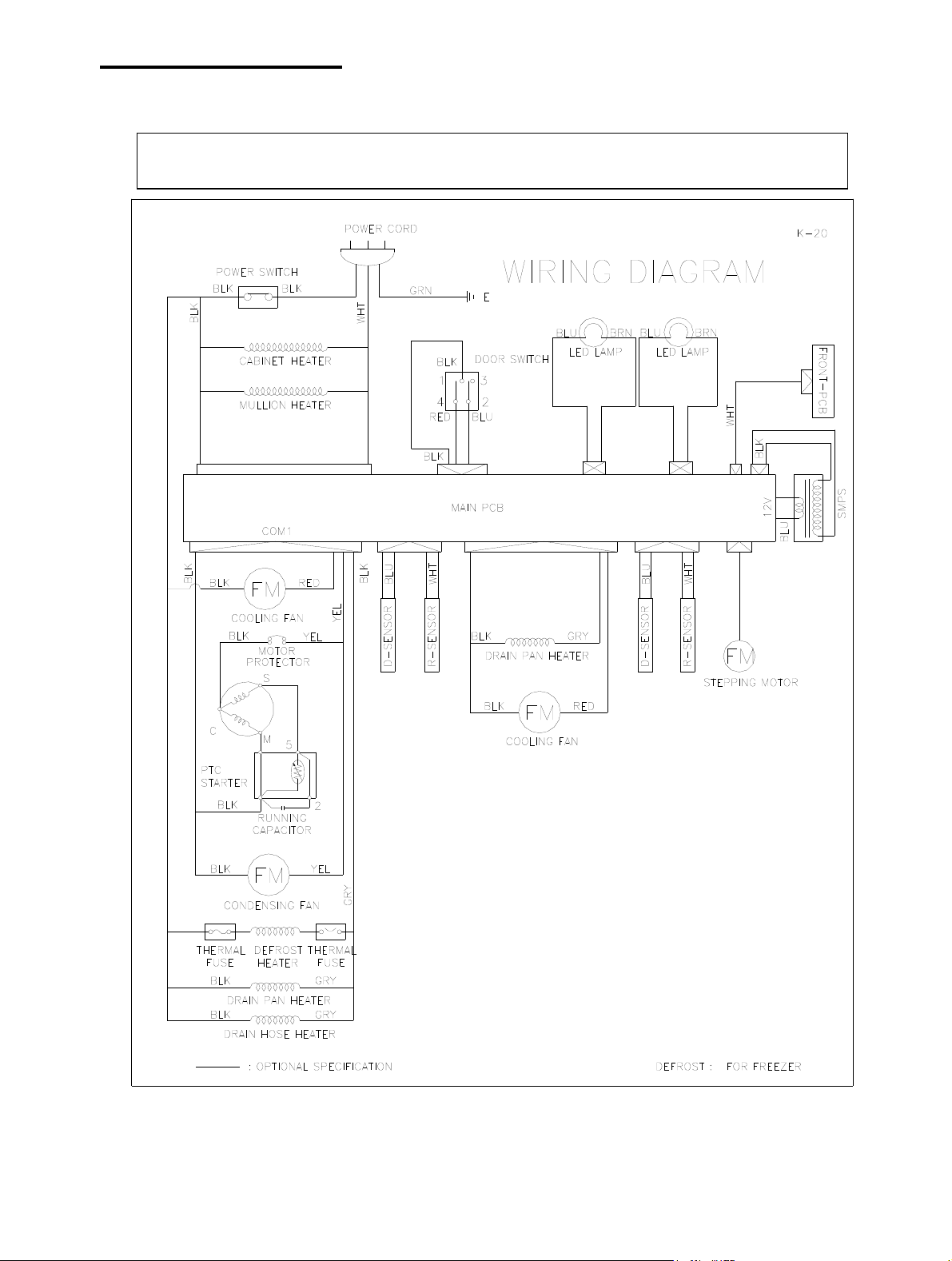
2.WIRING DIAGRAMS
2-1.
WIRING DIGRAM
2
Page 5
3.PART DETAIL
3-1.TOP GRILLE
TOP GRILLE (T), TOP GRILLE (B)
4
FRONT P.C.B
3-2.Refrigeration Compartment
Cycle Assembly
3
1
2
FRONTP.C.B(DUAL)
K3D5400300
1
1 TOP GRILLE(T) K1F1600200
2 FRONT PCB CASE K3F4740200
3 TOP GRILLE(B) K1F1600400
4 DOOR LOCK P998200100
1 COMP(NEK2150GK) G1D5700100
2 SUCTION PIPE(A) K1D4600100
7
3
FREEZER
4
6
5
IN (Dryer
3 DRYER BR84100100
4 CONDENSER K1D4400300
2
5 CONDENSER FAN MOTOR G8F6600100
6 CONDENSER FAN BLADE M722700401
7 STEPPING MOTOR K1D6900100
REFIGERATOR
STEPPING MOTOR
3
Page 6
PART DETAIL
Drain Pan Assembly
Drain Case Assembly
1
1 DRIAN PAN HEATER K3F5301101
2 DRAIN GUIDE K3F2500100
3 DRAIN CONNECTOR G8F3200601
2
4 DRAIN HOSE HEATER T8F5300300 FREEZER
3
4
1
5
1 DRAIN HOSE CAP K3F2500300
3
2 DRAIN CASE G8F3200107
3 DRAIN PIPE K1D4200202
4 DRAIN PIPE GUIDE G8F2500101
4
5 DRAIN CASE BRACKET G8F1400600
Condenser Fan Motor Assembly
2
1 CONDENSER FAN MOTOR G8F5000200
1
2 CONDENSER FAN BLADE M722700401
3 CONDENSER MOTOR BRACKET K1D7200100
2
3
4
Page 7
PART DETAIL
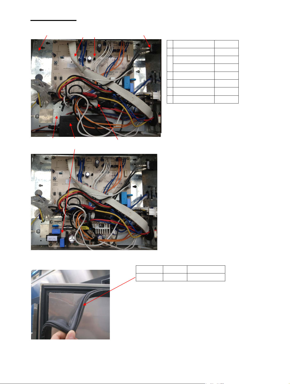
3-3.CONTROL BOX
1
4
3 7
2 6
5
1 ELEC BOX K3F1900100
2 MAIN PCB G1D5400100
3 SMPS(2013-2014.4) K3F6001000
SMPS(2014.5- ) KF81530100
4 ELEC BOX INNER COVER K3F1900200
5 POWER SWITCH 30281Q0100
6 HARNESS DISPLAY PCB K3F5104000
7 HARNESS MAIN K1D5100100
3-4.DOOR
GASKET
DOOR GASKET K3R3300204 REFIGERATOR
DOOR GASKET K3F3101005 FREEZER
5
Page 8
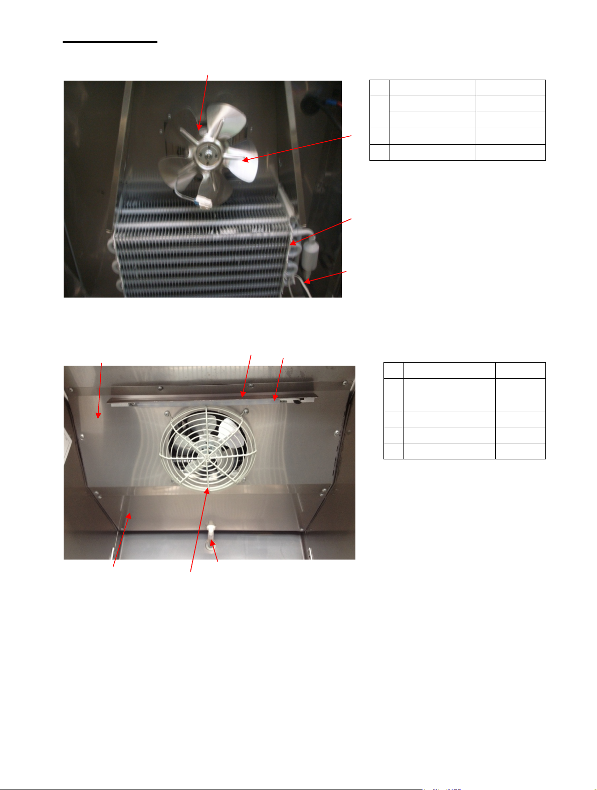
PART DETAIL
4
EVAP.Fan
Freezer Duct & Refrigerator Duct
6
5
4
1 EVAP FAN MOTOR K3F0500100
2 EVAP FREEZER K1D4400100
EVAP REFIGERATOR K1D4400200
1
3 D SENSOR K3F5102001
4 EVAP MOTOR G8F5000300
2
3
1 EVAP HOUSING COVER(B)
2 DRAIN HOSE G8F3000100
3 FAN COVER K1D9000200
4 LED LAMP P996300203
5 LED LAMP COVER G2F1700600
6 EVAP HOUSING COVER(F) K1D2100400
K3R2100203
1
3
2
6
Page 9
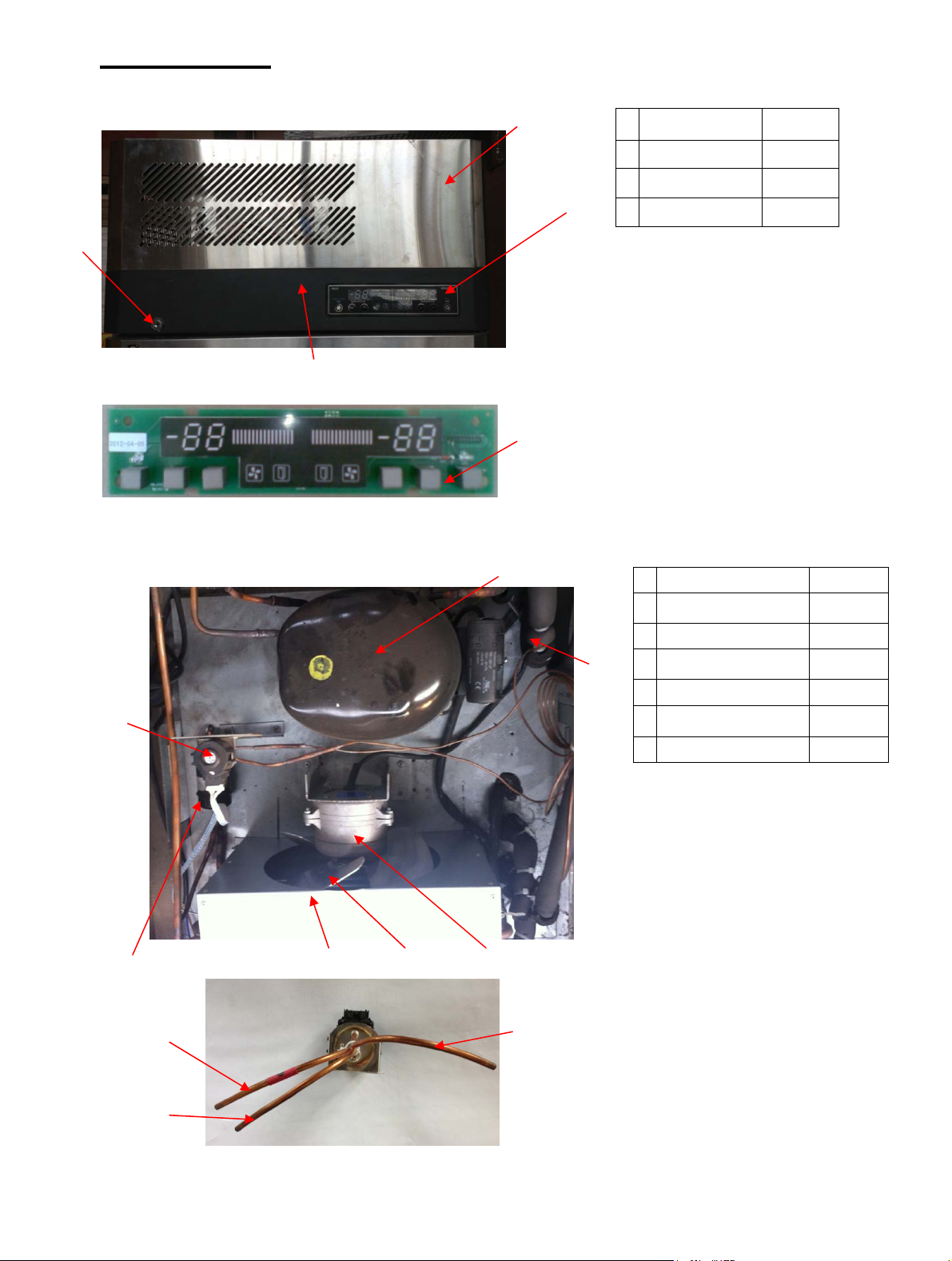
MAIN COMPONENTS
4-1.COMPRESSOR
model
refrigerant
Voltage
Comp. model
Part code
Starting Type
JRF-19
R404a
115
NEK2150GK
G1D5700100
4-2.CONDENSER DRYER
Model
Refrigerant
Spec.
Part code
JRF-19
R-404a
C-052-S
M726800100
4-3.CAPACITOR
Model
Voltage
Running
JRF-19
115
165Vac 189-227uf
Starting
——
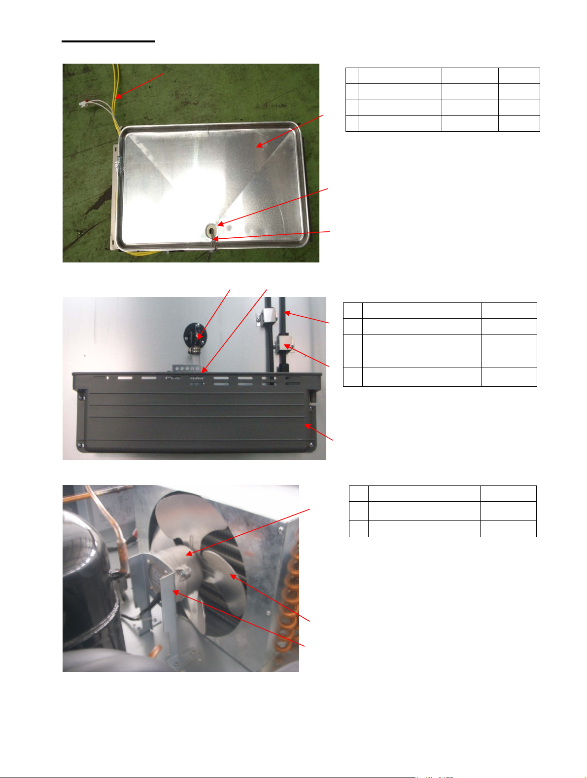
4-4.EVA FAN MOTOR
Model
Voltage
Motor
Model.
Part
code
JRF-19
115
IS4420ODWSN-2A
P8F5000300
4-5.CONDENSOR FAN MOTOR
MODEL
Voltage
Motor
Model
Part code
JRF-19
115
IS4420DWSG-1
G8F6600100
7
Page 10

MAIN COMPONENTS
4-6.EVA DEFROST HEATER
Model
Voltage 115V
Spec 280W
Part code K2D5301001
JRF-19
4-7.LED LAMP
Model
Voltage 12
Spec.
Part code P996300202
JRF-19
2.9W
4-8.MAIN PCB
Model
Voltage 115
Spec.. 88 SEGMENT
Part code G1D5400100
JRF-19
4-9.SMPS
2013-2014.4
Model
Voltage 115V 60HZ
Spec.. OUT:12V/8W
Part code K3F6000700
2014.5∼
Model
Voltage 115V 60HZ
Spec.. OUT:12V/20W
Part code KF81530100
JRF-19
JRF-19
4-10.DOOR SWITCH
Model
Voltage 115
Spec.. 1.0A
Part code K1D5200100
JRF-19
8
Page 11

5.ELECTRONICCONTROLLERINSTRUTION
5-1.HOW TO USE THE PANEL
9
Page 12

Part list
Part name Code
ASS’Y DOOR(T)(R) K1DFC00100 URETHANE ASSY 1
ASS’Y DOOR(U)(R) K1DFC00200 URETHANE ASSY 1
AIR DUCT K1D1900100 GI 0.4T 1
BOTTOM HINGE (R) K3F2901700 SUS304-2B 3.5 1
CASTER G8F6500201 STOP 4 INCH 2
CASTER G8F6500101 MOVE 4 INCH 2
COMPRESSOR G1D5700100 NEK2150GK 1
CONDENSER MOTOR BRACKET K1D7200100 GI 2T 1
D/K BRACKET K1D7200200 GI 2T 1
DOOR STOPPER(B) B1R0500600 SUS304-2B 1.5T 1
DOOR SWITCH K1D5200100 115V 1.0A 1
DRAIN CASE G8F3200107 PP 1
DRAIN CONNECTOR A G8F3200601 NY66 1
DRAIN CONNECTOR B G8F3200700 NY66 1
DRAIN GUDIE PAD K3F7300103 F-PS 1
DRAIN GUIDE K3F2500100 AL 1T 1
DRAIN HOSE CAP K3F2500300 ABS 1
DRAIN HOSE GUIDE G8F3200402 PA66 1
DRAIN HOSE HEATER T8F5300300 115V 10W L=700mm 1
DRAIN PAN HEATER K3F5301101 115V 55.6W L=3185mm 1
DRAIN PIPE(R) K1D4200202 CU 1
EVAP COIL K1D4400100 FRE 1
EVAP COIL K1D4400200 REF 1
EVAP HOUSING COVER(B) K1D2100300 AL 2
EVAP HOUSING COVER(F) K1D2100400 AL 2
FAN BLADE M722700401 Ф200 CCW AL 1
FAN BLADE B3D2700200 Ф150 CW AL 1
FAN COVER K1D9000200 SWRM 2
FILTER DRYER 052S M726800101 052S, Spoulan 1
FIN-CONDENSER K1D4400300 CU 1
FRONT PCB K3F5400100 °F 1
FRONT PCB CASE K3F3200400 ABS 1
HARNESS DISPLAY PCB K3F5101900 HARNESS 1
HARNESS MAIN K1D5100100 HARNESS 1
HEATER CABINET G2R1990100 SILICON 1
HEATER DEFROST K2D5301001 SUS-PIPE 1
HEATER MULLION(HOR) G1D5300100 SILICON 1
10
Material Q’TY
Page 13

Part name Code
LED LAMP P996300203 12V 2.9W L=307mm 2
K3F6001000 INN115V~230V OUT12V 8W 1
SMPS
KG81530100 INN115V~230V OUT12V 20W 1
MAIN PCB G1D5400100 115V 1
MIDDLE HINGE (R) K3F2901900 SUS304-2B 3.5T 1
MOTOR G8F6600100 IS 4420DWSG-1 (CCW) (115V-47W) 1
MOTOR G8F5000300 IS 4420DWSN-2A (CW) (115V-43W) 2
MULLION FRAME COVER(H) K1F3100500 PVC 2
MULLION OUT COVER K1D1200200 SUS439-#4 0.6T 1
PIPE(DRYER-CAPI TUBE) K1D4600500 CU 1
PIPE(TEE-SUC) K1D4600300 CU capillary IDФ1.2 L=1600mm 1
PIPE(COMP-DRAIN) K1D4200600 CU 1
PIPE(CON-DRAIN) K1D4600400 CU 1
POWER SWITCH 30281Q0100 1
R SENSOR K3F5102100 1
SHELF K1F9000102 SWRM 2
SHELF STANDARD K3F2700103 SUS304-2B 4
STOPPER SPRING PLATE(R) B1R0501101 SUS304-2B 1
SUCTION PIPE(A) K1D4600100 CU capillary IDФ1.2 L=2000mm 1
THERMAL FUSE T8F6200200 N80 1
TOP GRILLE (B) K1D1600100 EGI BLACK 1
TOP GRILLE (T) K1F1600200 SUS439-#4 1
TOP HINGE (R) K3F2901500 SUS304-2B 3.5T 1
STEPPING MOTOR K1D6900100 1
HARNESS STEPPING MOTOR K1D5100400 HARNESS 1
Material Q’TY
11
Page 14

7.REPLACEMENT OF MAIN COMPONENTS
7-1. TOP GRILLE PART
A. Unscrew the screw located on both side of top grille (t) with the top grille (t)
fixture
B. Hold up the top grille (T)
C. Unscrew the screw located on both side of top grille (B).
12
Page 15

REPLACEMENT OF MAIN COMPONENTS
D. Unscrew the screw located on the cabinet top cover.
E. Pull out the harness display pcb located on back of top grille (B).
You can replace the mascot, key, front pcb and front pcb case, etc.
13
Page 16

REPLACEMENT OF MAIN COMPONENTS
7-2. REPLACE DOOR
A. Disassemble top grille (t) and top grille (b) as described section 7-1.
B. Unscrew the top hinge
C. Lift the door (T) and pull it out.
7-2.REPLACE DOOR
D. Unscrew the middle hinge
14
Page 17

REPLACEMENT OF MAIN COMPONENTS
E. Lift the door (U) and pull it out.
Then you can replace new doors and assemble them, those processes are opposite to
disassemble them.
15
Page 18

REPLACEMENT OF MAIN COMPONENTS
7-3. REFRIGERATION COMPARTMENT’S PART
- Duct and Lamp
- T-sensor and D-sensor
- Evaporator coil andF-sensor
- Defrost heater (freezer only)
- Evaporator fan motor and fan blade
7-3-1. REPLACE DUCT AND LAMP
A.Disassemble the Duct.
7-3-2. REPLACE D SENSOR (BLUE)
A.Disassemble the Duct as in 7-3-1
B. Disconnect the connector and pull out the D-sensor from the evap.replace the
new one.
16
Page 19

REPLACEMENT OF MAIN COMPONENTS
C.Take off the thermal fuse from the evap.replace the new one.
7-3-3. REPLACE THE EVAPORATOR COIL AND R-SENSOR
A. Welding off the connection suction pipe(B) and evap.
B. Unscrew the screw located on back side of evap. housing.
17
Page 20

REPLACEMENT OF MAIN COMPONENTS
C. Take off the evaporator.
D. Disconnect the connector and Unscrew the screws located on sensor cover and
pull out the R-sensor from the evap.sensorguide,replace the new one.
7-3-4. REPLACE THE DEFROST HEATER (FREEZER ONLY)
A. After lift the evaporator up, disconnect the connectors with harness defrost
heater and disassemble the defrostfixturespring and split the hooks of the
evap..
18
Page 21

B. Replace the new defrost heater and fix it with heater fix spring.Connect the
connectors.
REPLACEMENT OF MAIN COMPONENTS
How to measure the Amps.of the evaporator defrost heater
Disconnect the connectors of the evaporator defrost heater.
Then , prepare the additional Power Source(220V/50Hz) and the Amp. Meter.
Connect the connectors of the evaporator defrost heater to the additional power source
and read amp. Value from the Amp.Meter.
7-3-5. REPLACE THE EVAPORATOR FAN MOTOR AND FAN BLADE
A. After lift the evaporator up, unscrew the screw which used in fixing motor
fixture.
B. Disconnect the connectors of harness motor.
19
Page 22

Then you can replace the evaporator fan motor and fan blade.
REPLACEMENT OF MAIN COMPONENTS
7-4. CONTROL BOX PART
- Power relay
- Transformer
- Main PCB
A. Disassemble top grille (t) as described section 7-1 A B.
B. Pull out all connectors connected with control box.
C. Unscrew the screws located on front of evap-housing.
E. Pull out the harness main.
F. Unscrew the screws used in fixing power relay and trans former.
20
Page 23

G. Disconnect the main PCB fixture.
Then you can replace the power relay, trans former and main pcb.
REPLACEMENT OF MAIN COMPONENTS
7-5. CONDENSER UNIT
- Compressor
- Condenser fan motor(Fan Blade Ф200)
- Dryer filter
- Stepping Motor
- Condenser
The comp. Base is locatedon both side on the top of the cabinet by screw, and you can replace the
Compressor ,stepping motor,dryer,suctionpipe,Condenser coil Condenser fan motor, ETC. on it.
21
Page 24

REPLACEMENT OF MAIN COMPONENTS
7-6. REPLACE THE CABINET HEATER AND MULLION HEATER
A. Disassemble the liner frame cover with the and edge of ‘一’type
screwdriver.(left/right/top/bottom side)
22
Page 25

B. Disconnect the cabinet heater and pull it out.
You can replace the cabinet heater with the new one.
C. Assemble the liner frame cover.(left/right/top/bottom side)
REPLACEMENT OF MAIN COMPONENTS
D. Disassemble the mullion frame cover with the and edge of ‘一’type screwdriver.
23
Page 26

E. Take apart the mullion out cover from the mullion, then disconnect the harness
mullion heater and harness door switch
F. Change the old mullion heater/door switch and install the new one with the gap
between wires 1.2 inch.
G. Insert the mullion out cover into the original position, then screw it on both side
of the mullion.(this process is opposite to disassemble the mullion out cover )
24
Page 27

H. Assemble the mullion frame cover.(this process is as alike as assembling the
liner frame cover)
25
 Loading...