

Page 1
CAUTION!
PLEASE KEEP POWER
SWITCH ON BEFORE
OPERATING THIS EQUIPMENT
Turbo Air Speed up the Pace of Innovation
Salad Table
Refrigerator & Freezer
Service Manual
Please read this manual completely before attempting to install or operate this equipment!
Sandwich Salad Unit
JBT-36
JBT-48
JBT-60
JBT-72
www.turboairinc.com
Page 2

TABLE OF CONTENTS
1. EXPLODED VIEW
1-1. JBT-36 EXPLODED VIEW
1-2. JBT-48 EXPLODED VIEW
1-3. JBT-60 EXPLODED VIEW
1-4. JBT-72 EXPLODED VIEW
2. WIRING DIAGRAMS
3. MAIN PART
4. MAIN COMPONENTS
5. PARTS LIST
6. TEMPERATURE CONTROL INSTRUCTION
7. REPLACEMENT OF MAIN COMPONENTS
7-1. REPLACING DOOR
7-2. REFRIGERATION COMPARTMENT PARTS
7-3. COMPRESSOR COMPARTMENT PARTS
7-4.DISASSEMBLE Refrigerator Compartment
7-5 Replacing FRONT PCB
7-6 How to use Display PCB
7-7 Replace Main PCB
7-8 Replacing cabinet frame heater(and/or)mullion heater
Page 3
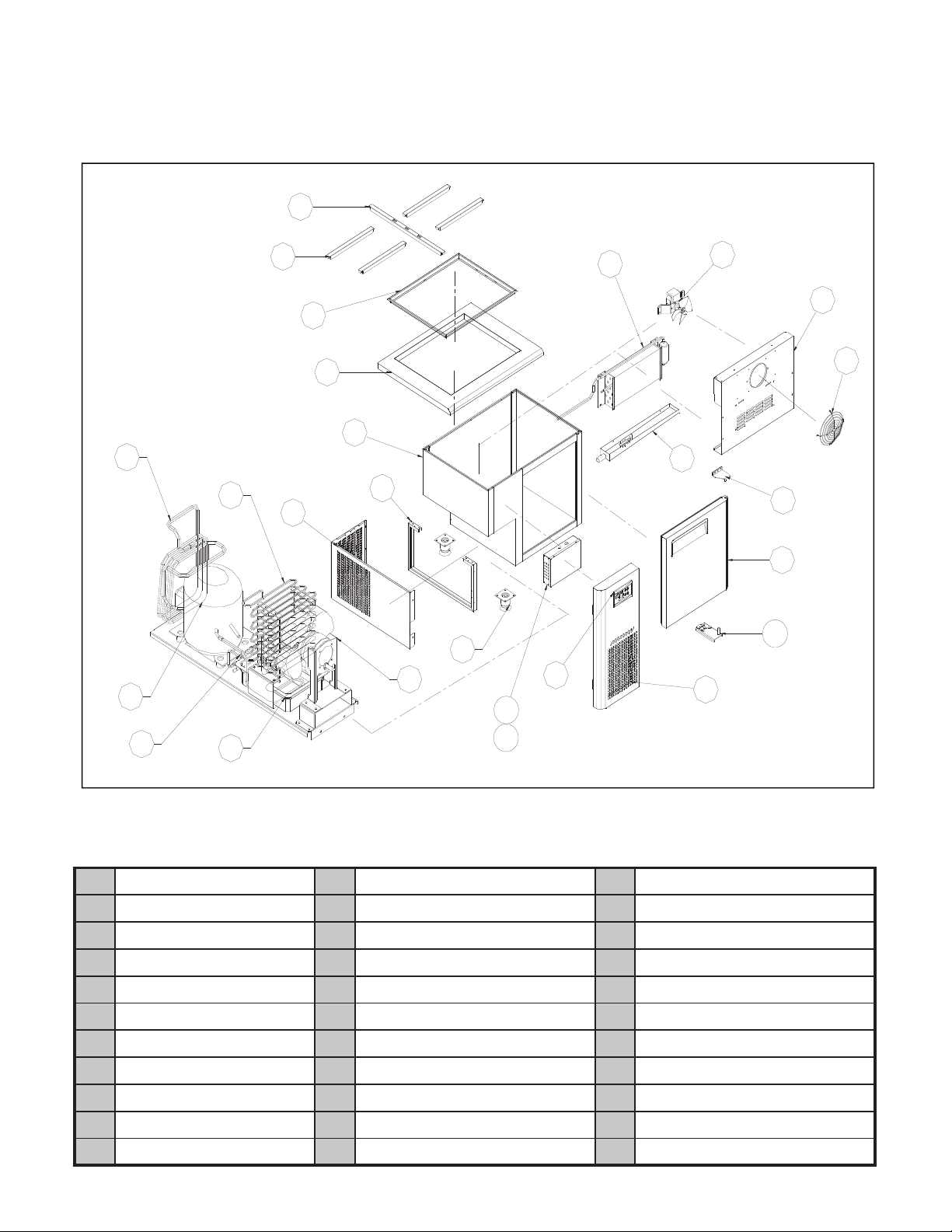
1. EXPLODED VIEW
1-1. JBT-36 EXPLODED VIEW
11
19
20
18
12
17
13
14
15
16
23
24
25
10
9
8
7
6
5
4
3
1
2
21
Part Name
Display PCB
1
Assy Front Cover
2
Bottom Hinge R
3
Assy Door R _ 900
4
Top Hinge R
5
Drain Guide
6
Fan Cover Wire
7
Evap Duct Cover
8
Assy Evap Fan Motor
9
Evaporator
10
Pan Guide
11
22
Pan Guide S
12
Assy Pan Support
13
Assy Counter Top
14
Assy Cabinet
15
Unit Reinfoce
16
Unit Side Cover
17
Condenser
18
Suction Pipe
19
Comprssor
20
Dryer
21
Drian Pan
22
26
Assy Condenser Motor
23
Caster
24
Trans
25
Main PCB
26
Page 4

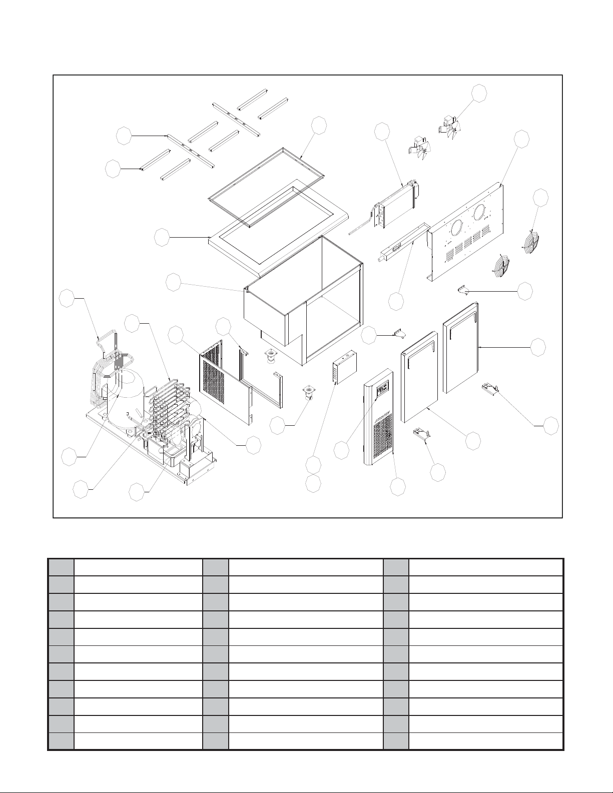
1-2. JBT-48 EXPLODED VIEW
9
19
12
11
18
14
15
17
16
13
27
10
8
7
5
6
4
20
21
Part Name
Display PCB
1
Assy Front Cover
2
Bottom Hinge R
3
Assy Door R
4
Top Hinge R
5
Drain Guide
6
Fan Cover Wire
7
Evap Duct Cover
8
Assy Evap Fan Motor
9
Evaporator
10
Pan Guide
11
22
23
Pan Guide S
12
Assy Pan Support
13
Assy Counter Top
14
Assy Cabinet
15
Unit Reinfoce
16
Unit Side Cover
17
Condenser
18
Suction Pipe
19
Comprssor
20
Dryer
21
Drian Pan
22
24
25
26
3
29
1
28
2
Assy Condenser Motor
23
Caster
24
Trans
25
Main PCB
26
Top Hinge L
27
Bottom Hinge L
28
Assy Door L
29
Page 5
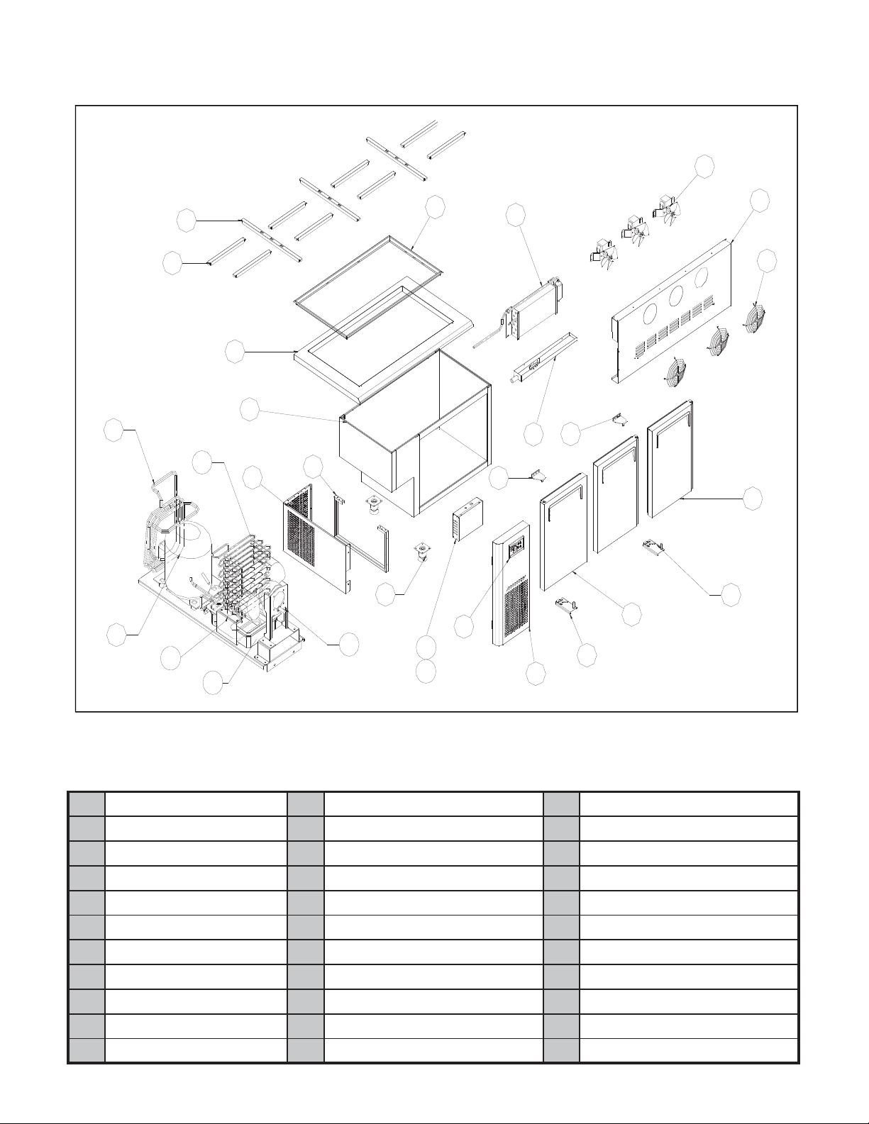
1-3. JBT-60 EXPLODED VIEW
9
19
12
11
18
14
15
17
16
13
27
10
8
7
5
6
4
20
21
Part Name
Display PCB
1
Assy Front Cover
2
Bottom Hinge R
3
Assy Door R
4
Top Hinge R
5
Drain Guide
6
Fan Cover Wire
7
Evap Duct Cover
8
Assy Evap Fan Motor
9
Evaporator
10
Pan Guide
11
22
23
Pan Guide S
12
Assy Pan Support
13
Assy Counter Top
14
Assy Cabinet
15
Unit Reinfoce
16
Unit Side Cover
17
Condenser
18
Suction Pipe
19
Comprssor
20
Dryer
21
Drian Pan
22
24
25
26
3
29
1
28
2
Assy Condenser Motor
23
Caster
24
Trans
25
Main PCB
26
Top Hinge L
27
Bottom Hinge L
28
Assy Door L
29
Page 6
1-4. JBT-72 EXPLODED VIEW
9
19
20
12
21
11
18
22
14
15
17
16
23
24
13
25
26
10
8
7
5
6
27
4
3
1
29
28
2
Part Name
Display PCB
1
Assy Front Cover
2
Bottom Hinge R
3
Assy Door R
4
Top Hinge R
5
Drain Guide
6
Fan Cover Wire
7
Evap Duct Cover
8
Assy Evap Fan Motor
9
Evaporator
10
Pan Guide
11
Pan Guide S
12
Assy Pan Support
13
Assy Counter Top
14
Assy Cabinet
15
Unit Reinfoce
16
Unit Side Cover
17
Condenser
18
Suction Pipe
19
Comprssor
20
Dryer
21
Drian Pan
22
Assy Condenser Motor
23
Caster
24
Trans
25
Main PCB
26
Top Hinge L
27
Bottom Hinge L
28
Assy Door L
29
Page 7
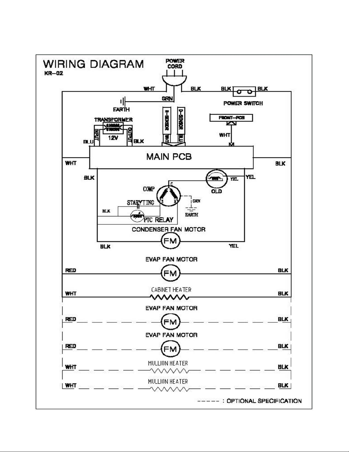
2. WIRING DIAGRAMS
Page 8

3.MAIN PART
DISPLAY PCB
DISPLAY PCB
CONDENSER UNIT
SUCTION PIPE(B) COMP CONDENSER FAN MOTOR
CONDENSER
DRYER DRAIN PAN
CONDENSER FAN MOTOR ASSY
DRAIN PIPE
CONDENSER MOTOR FAN BLADE
CONDENSER MOTOR BRACKET CONDENSER MOTOR
Page 9

PCB
BO
X
TRANSFORMER
DOOR GASKET
DOOR FRAME
MAIN PCB
EVAP UNIT
R-SENSOR D-SENSOR
DOOR GASKET
EVAP FAN MOTER
EVAP
EVA DRAIN GUIDE
Page 10

EVAP DUCT
FAN COVER
EVAP DUCT
4. MAIN COMPONENTS
1.COMPRESSOR
MODEL PART NAME PART NO. HP CAPACITY TYPE OF INPUT MAKER
JBT-36 HBL-27YE-1 M369700100 1/4 HP - RSCR 115V 60Hz DAEWOO
JBT-48 HBL-27YE-1 M369700100 1/4 HP - RSCR 115V 60Hz DAEWOO
JBT-60 HBL-27YE-1 M369700100 1/4 HP - RSCR 115V 60Hz DAEWOO
JBT-72
2. COMPRESSOR RELAY , OVERLOAD
MODEL
JBT-36
JBT-48
JBT-60
JBT-72
HBL-27YE-1 M369700100 1/4 HP - RSCR 115V 60Hz DAEWOO
SENSATA- 4TM314TFBYY-52
- 4TM314TFBYY-52 SENSATA
SENSATA- 4TM314TFBYY-52
- 4TM314TFBYY-52
SENSATA
NOTEMAKEROVERLOADRELAY
3. COMPRESSOR CAPACITOR
MODEL
JBT-36
JBT-48
JBT-60
JBT-72
STARTING
200V/100µF
200V/100µF
200V/100µF
200V/100µF
PART NO. RUNNING
-
-
-
-
4. CONDENSER FAN MOTOR
JBT-36
JBT-48
JBT-60
JBT-72
5. EVAPORATOR FAN MOTOR
PART NAME PART NO. POLE INPUT TYPE BLADE MAKERMODEL
JBT-36
JBT-48
JBT-60
JBT-72
IS-3220QTBA
M729900201 2P 115V,60Hz
6. CAPILLARY TUBE LENGTH AND REFRIFERANT
MODEL
JBT-36
JBT-48
JBT-60
JBT-72
CAPILLAY LENGTH Refriferant MAKER NOTE
OD2.4,ID1.2,L=2530
OD2.4,ID1.2,L=3030
OD2.4,ID1.2,L=3030
OD2.4,ID1.2,L=3530
230V/10µF
230V/10µF
230V/10µF
230V/10µF
7.0oz
7.0oz
8.5oz
10.6oz
PART NO.
-
-
-
-
INPUTMODEL POLE
TYPEPART NAME PART NO.
SHADED POLE
INDUCTION
SHADED POLE
INDUCTION
MAKER
-
-
-
-
BLADE MAKER
3LAzH06,V511P40010066F8G1-GSWD0244 SI
ZYTEL
4
SUNGSHIN
SUNGSHIN
NOTE
-
-
-
-
Page 11

7.FILTER DRYER
MODEL
JBT-36
JBT-48
JBT-60
JBT-72
PART NO. REFRIGERANT SPEC NOTE
BR84100101
BR84100101
BR84100101
BR84100101
5. PARTS LIST
PART NAME PART CODE DESCRIPTION REMARK
ASSY COUNTER TOP BR2FF00100
ASSY COUNTER TOP
ASSY COUNTER TOP
ASSY COUNTER TOP
ASSY PAN SUPPORT
ASSY PAN SUPPORT
ASSY PAN SUPPORT
ASSY PAN SUPPORT
PAN GUIDE
PAN GUIDE(S)
ASSY DOOR_900 (R)
ASSY DOOR_1200 (L)
ASSY DOOR_1200 (R)
ASSY DOOR_1500 (L)
ASSY DOOR_1500 (R)
ASSY DOOR_1800 (L)
ASSY DOOR_1800 (M)
ASSY DOOR_1800 (R)
DOOR GASKET_1200
DOOR GASKET_1500
DOOR GASKET_1800
DOOR GASKET_900
DOOR BUSHING
SPRING BAR
SPRING BAR
BOTTOM HINGE (U) (L)
BOTTOM HINGE (U) (R)
DOOR TOP HINGE (L)
DOOR TOP HINGE (R)
COMPRESSOR
EVAP_12/1500
EVAP_1800
EVAP_900
BR5FF00100
BR8FF00100
BR9FF00100
BR21800200
BR51800200
BR81800500
BR91800200
BR81800400
BR81800301
KR9AF00102
KR2AF00202
KR2AF00102
KR5AF00202
KR5AF00102
KR8AF00202
KR8AF00302
KR8AF00102
KR23300103
KR53300103
KR83300103
KR93300103
M720700101
BR98400100
BR98400200
30229M0305
30229M0405
M722900206
M722900106
M369700100
BR2AD00103
BR8AD00103
BR9AD00103
R-134A
R-134A
R-134A
R-134A
PVC
PVC
PVC
PVC
ABS
SUS
SUS
SUS
SUS
HBL-27YE-1
CU
CU
CU
C-052-5
C-052-5
C-052-5
C-052-5
MODEL
9121518
1
1
1
1
1
2
46810
1
1
1
2
1
2446
2
1
111
1112
111
1112
1111
11
-
-
-
-
1
1
1
1
3
4
1
1
1
1
1
2
3
3
2
1
1
Page 12

PART NAME PART CODE DESCRIPTION REMARK
DRYER
CONDENSER
CONDENSER
CONDENSER FAN MOTOR
EVAP FAN MOTOR
DISPLAY PCB
MAIN PCB
POWER CORD
R SENSOR (S/P)
D SENSOR (S/P)
TRANS
MAIN PCB COVER(B)
MAIN PCB COVER(F)
ASSY MAGNET
ASSY MULLION
ASSY MULLION (B)
ASSY UNIT FRONT COVER
EVA DRAIN GUIDE_1200
EVA DRAIN GUIDE_1500
EVA DRAIN GUIDE_1800
EVA DRAIN GUIDE_900
UNIT SIDE COVER
EVAP DUCT_1200
EVAP DUCT_1500
EVAP DUCT_1800
EVAP DUCT_900
SHELF STANDARD
FIXTURE SHELF CLIP
SHELF_1200
SHELF_1500
SHELF_1800
SHELF_900
CASTER
CASTER
FAN COVER WIRE
DRAIN PAN
FRONT PCB CASE
POWER SWITCH
DRAIN HOSE
CABINET HEATER
CABINET HEATER
CABINET HEATER
CABINET HEATER
MULLION HEATER
BR84100100 CU 1 1 1 1
KF24900104
KF84900105
G8F6600100
M729900201
KR85400100
BR85400100
CM71300200
K3F5102101
K3F5102001
K3F6000100
KR81400100
KR81400200
KR89900200
KR9AC00100
BR8AC00100
KR81900302
BR21900102
BR51900102
BR81900102
BR91900102
KR81900104
BR21700101
BR51700101
BR81700101
BR91700101
M725300201
30220L0903
BR29000102
BR59000102
BR89000102
BR99000102
G8F6500101
G8F6500201
U609000100
30211A0202
KR93200300
30281Q0100
BR93000100
JR25300102
JR55300102
JR85300102
JR95300102
JR85300201
SUS
SUS
02-10-201-10
SUS
SUS
SUS
SUS
SUS
SUS
SUS
SUS
SUS
SUS
PA-66
PE-CO (GRAY)
PE-CO (GRAY)
PE-CO (GRAY)
PE-CO (GRAY)
MOVE 4 INCH
STOP 4 INCH
P.P
ABS
ABS
PVC
OPTION
OPTION
OPTION
OPTION
OPTION
MODEL
9121518
111
1111
1223
1111
1111
1111
1111
1111
1111
1111
1111
2222
111
1111111
1
11111
1
48812
48
11
2224
2222
12223
1111
1111
1111
11111
812
2
2
1
11
1
1
1
1
2
1
1
Page 13

6. TEMPERATURE CONTROL INSTRUCTION
Page 14

7.REPLACEMENT OF MAIN COMPONENTS
7-1.REPLACING DOORS
A.Unscrew the screws on top hinge B.Take o top hinge
C.Take o doors
7-2.REFRIGERATOR
A.Unscrew the screws on EVAP DUCT
B.DOOR ASSY
B.Take o EVAP DUCT C.Take o SENSOR
Page 15

D.Disassemble EVAP MOTOR E.Pull out the EVAP
7-3.MECHANICAL ROOM
A.Take o the UNIT FRONT COVER
B.Take o the UNIT SIDE COVER
C.Take o the MACH COVER
7-2.REFRIGERATOR
E.Pull-out MECHANICAL ROOM
D.Unscrew the secrews on COMP BASE
Page 16

A.Unsolerder SUCTION PIPE(B) and COMP as below
C.Disassemble the COMPRESSOR D.Take apart the CONDENSER MOTOR
B.Unsolder CONDENSER and DRAIN PIPE as below
E.Disassemble the CONDENSER F.Disassemble lter dryer
7-5 Replace Front PCB
A.lift the unit front cover as illustrated below.
B.Switch o the power.
C.Unplug
D.Remove the display PCB back cover by unscrewing the
four screws located on the display PCB back cover.
Page 17

E.Disassemble display PCB. F.Replace display PCB with the new one.
G.Screw the display PCB. H.Tighten the screws located on display PCB back cover.
I.Put the plug in the socket. J.Turn on the unit.
7-6 How to use Display PCB
A.Push"SW1" and "SW2" button (SWI▼. SW2▲ )at
the same time and wait ve seconds to set mode.
B.Bar LED display "F1",the unit is at the mode of freezer.
Page 18

C.Then push"SW1" button (SWI▼) one time,the
unit is at the mode of freezer(F2).
E.Turn o the power after setting the necessiry
mode,then restart the power.
D.Push"SW1" button (SWI▼) agian,the unit is at the
mode of refrigerator(R1).
7-7 Replace Main PCB
A.lift the unit front cover as illustrated below. B. Unscrew the main PCB cover (front).
Page 19

C.Unscrew the the main PCB cover(back). D.Disconnect the connectors.
E.Figure of the removed connectors. F.Separate the PCB.
G.Take apart the main PCB from electrical box. H.Replace the main PCB with the new one.
I.Connect connectors of main PCB. J.Tighten the screws as below.
Page 20

K.Assemble the unit front cover.
7-8 Replacing cabinet frame heater(and/or)mullion heater
A.Insert thepoint of“-”type screw driver into the gap
between the frame and frame cover.
B.Take apart the frame cover from the frame.
C.Pull out the heater wire from the inlet. D.Insert new cabinet heater wire to the inlet.
E.Assemble the frame cover with frame.Pat the frame
cover with the soft hammer,etc.
F.Disassemble the mullion frame.
Page 21

G.Uncap connectors of mullion heater. H.Take apart mullion frame cover from mullion frame.
I.Replace the mullion heater with a new one.
 Loading...