


ALLSTEADY-7 GIMBAL MANUAL V1.1
redefining flight

TABLE OF CONTENTS
I. QUICK START GUIDE
II. BATTERY CHARGER
III. BALANCING YOUR GIMBAL
o Horizontal Tilt
o Vertical Tilt
o Roll Balance
o Pan Balance
1
IV. GIMBAL BALANCING STAND
V. OPTIONAL EQUIPMENT
VI. PROGRAM MODES
VII. INVERTED and SIDEWAY SHOOTING
VIII. WIRELESS RECEIVER CONNECTIONS
IX. SOFTWARE
TURBO ACE
2
ALL STEADY 7

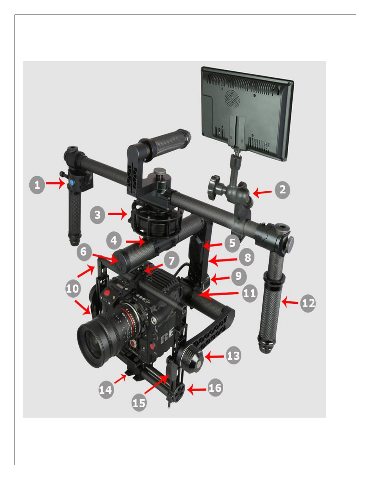
AllSteady-7 Diagram & Options:
Match the designated numbers from the picture on page 2 to the list on page 3
1) Reversible Left/Right Handed Joystick Module
2) Monitor Bracket & Articulating Arm
3) Motor Cage & Ultra Resolution Pan-Axis Brushless Motor
4) No tools necessary for Pan-Axis CG Adjustment
5) Aux Electronic Compartment for 2nd Sensor & Optional Aux Power
6) Integrated Battery Compartment
7) Quick Release Camera Top Mount Bracket Adjustment
8) Main Electronic Compartment for 32Bit Alexmos Dual Sensor Controller
3
9) High Torque Roll-Axis Brushless Motor
10) Triple Carbon Boom Camera Tray (2 Bottom Booms + 1 Top Boom)
11) No tools needed for Macro-Roll Adjustment
12) Rubber Grip Handle Adjustable in 45° Increments
13) Tilt-Axis Brushless Motor with Anti-Twist Stopper
14) Double Quick Release Micro-Roll Adjustment Lock
15) Quick Release Vertical CG Adjustment
16) Tool-less Micro-Roll Adjustment wheel

Thank you for purchasing the AllSteady-7 Gimbal
[Before getting started, please follow our balancing guide. We recommend you have your camera and
accessories (i.e. filter, batteries, etc.) mounted before balancing the gimbal. If your lens has an adjustable
zoom, set the zoom to the desired position before balancing.]
FOR YOUR CONSIDERATION
All TurboAce warranties, instructional manuals, or any miscellaneous documentation for the AllSteady-7
must be speculated. TurboAce does their best to resolve any technical errors in order to increase the overall
efficiency of the AllSteady-7.
DISCLAIMER
While the AllSteady- 7 does not require a license to use, please regard this as an advanced cinema product
that must be handled with caution and good judgment. A basic understanding of mechanical functions is
needed in order to operate the AllSteady 7 safely and responsibly. Failure to do so could not only result in
injury of yourself and others, but irreparable damage to your gimbal.
4
It is essential to read our User Manual to ensure a safe and smooth experience. Please note that this guide
should be viewed “as is” and Turbo Ace will not be held responsible for any contrary interpretation made by
the user that is different from what the manual intended. Turbo Ace reserves the right to adjust the manual
when needed and is not committed to alert any user of such changes.
ALLSTEADY-7 WARRANTY
Turbo Ace offers a limited year warranty where all service and parts support is provided from Turbo Ace’s
warehouse and showroom located in Orange, California.
1 Year Limited Warranty on Parts
30 Days Warranty on Parts & Labor
30 Days Warranty on Battery
30 Days Phone Support

I. Quick Start Guide
WARNING BEFORE USE
1) Remove the gimbal from the box.
2) Make sure power is turned off at the back of the gimbal. The power switch is located at the back of the gimbal
on top of the battery indicator. Pressing the "0" down will power the unit off.
3) Charge the battery by following the instruction on Section II. Remove the battery cap located in front of the pan
motor at the end of the carbon tube. Insert the battery into the tube and plug in the battery connector. Replace
the battery cap to the battery compartment tube.
4) Before setting the gimbal on the balancing stand, please follow the balancing stand setup on Section IV.
5) All gimbal requires balancing to establish center of gravity for each camera. When balance is not obtained, the
gimbal will vibrate during operation. When that happens, please set gimbal on the stand and follow the
balancing procedure on Section III.
6) Turn on the gimbal by pressing down the "I" on the power switch. Gimbal must be stationary during
initialization. Gimbal cannot be moved during initialization. Before turning on the power, please set the gimbal
down on the ground or on the balancing stand and prevent it from moving until the motors are initialized.
When you see the motors twitch, initialization then been completed. You are now ready to use the gimbal.
7) When gimbal is initialized, it starts in mode #4. Please follow Section VI for detail on how these
preprogrammed modes work.
8) The AllSteady 7 can be used in right side up or down configuration. Please see Section VII for detail.
5

II. Battery & Charger
Your AllSteady-7 comes with a smart lithium ion battery. There is a built-in controller in each battery pack
that monitors the voltage during charging and discharging.
WARNING BEFORE USE
**Never leave charger unattended, exceed maximum charge rate, charge with non-approved batteries or
charge batteries in the wrong mode.
**Always ensure the battery you are charging meets the specifications of this charger and that the charger
settings are correct. Not doing so can result in excessive heat and other related product malfunctions, which
can lead to user injury or property damage.
PLEASE DO NOT…
…leave the power supply, charger and battery unattended during use.
…attempt to charge dead, damaged or wet battery packs.
…attempt to charge a battery pack containing different types of batteries.
…allow minors to charge battery packs.
…charge batteries in extremely hot or cold places or place in direct sunlight.
…charge a battery if the cable has been pinched or shorted.
…connect more than one battery pack to this charger at a time
…connect the charger if the power cable has been pinched or shorted.
…connect the charger to an automobile 12V battery while the vehicle is running.
…attempt to dismantle the charger or use a damaged charger.
…reverse the positive and negative terminals.
…connect to AC power.
6
KEEP IN MIND TO ALWAYS…
…power on the charger before connecting the battery
…use only rechargeable batteries designed for use with this type of charger.
…inspect the battery before charging.
…keep the battery away from any material that could be affected by heat.
...monitor the charging area and have a fire extinguisher available at all times.
…end the charging process if the battery becomes hot to the touch or starts to change form (swell)
during the charge process.
**Failure to follow the advised steps while using this product will not only result in product malfunction,
but can cause severe injury and property damage.

BATTERY CHARGING AND INSTALLATION:
1. Connect power supply to power source.
2. Connect charger to the battery
3. Locate the battery compartment which is in the top pan boom (the top pan boom is located on top
of the gimbal).
4. Put the battery in compartment and hook up the connectors.
5. Install the battery cap; making sure the thumb screw on the cap is completely tightened. Turn on the
power, and you are ready to operate.
STOP
We strongly recommend that you DO NOT turn on your gimbal
7
if your camera is not mounted.

III. BALANCING YOUR GIMBAL
We recommend you have your camera and accessories (i.e. filter, batteries, etc.) mounted before
balancing the gimbal. If your lens has an adjustable zoom, set the zoom to the desired position before
balancing.
There are 4 axes that need to be adjusted to ensure proper operation for the gimbal. They include the
horizontal and vertical tilt, roll balance, and pan balance.
STEP 1: HORIZONTAL TILT
Balancing your gimbal horizontally (or front-to-back) is the first step to keep your camera level should you
remove your hands. Users must consider that in order to achieve this goal, the camera and Tilt Axis need to
be level. Since this is the first step, please note that the gimbal has not yet been balanced vertically for the
Tilt Axis. With this being said, it can be assumed that it will only be possible to verify the horizontal tilt to be
balanced once the camera and Tilt Axis are level. If the camera is situated too high or too low with respect to
the Tilt Axis, it can easily obscure the issue of the horizontal tilt being imbalanced. To adjust the balance,
please follow the directions below:
1) Loosen your tripod screw under the camera, allowing the camera and mount plate to slide forwards
and backwards. **If you have the optional quick-release plate, loosen the knob as indicated on the
picture below.
a. (add picture from balancing manual)
2) If the camera tilts down lens-first, slide the camera backwards. If the camera tilts so the lens faces
upwards, slide the camera forwards. Continue making incremental adjustments until the camera is
leveled when facing straight.
3) Make sure to confirm that the clamp is fully working and the camera is securely mounted to the
adjustable camera.
8

STEP 2: VERTICAL TILT
Once you have completed Step 1 in balancing your AllSteady-7 Gimbal, the Vertical (or up-and-down)
balance. In order to adjust the vertical tilt, you must locate the 2 toggle clamps on the four side tubed. Adjust
your camera’s position vertically until it is balanced efficiently enough to rotate your camera to any tilt angle.
Naturally it will stay wherever you position it. For example, if you point the lens down and you notice the tilt
wanting to continue tilting forward on its own, then that is an indicator that it is “top heavy” and the camera
needs to be shifted down vertically. Another example is if you point the camera lens down and it wants to
return to its original position, then it is “bottom heavy” and your camera needs to be shifted upwards. Please
follow the steps below:
1.) Observe which way you need to adjust your camera. You can do this by tipping the camera lens down
20 degrees. If the camera returns to horizontal, then the Tilt Axis is bottom heavy. If the camera continues
to rotate down when left to stay in position, then the Tilt Vertical Axis is top heavy.
2.) Rotate the Tilt Axis so that your camera lens is facing straight up.
3.) Make sure to loosen the 2 vertical adjustment toggles.
4.) Slide your camera mount beam and camera horizontally until it remains pointing straight up once
released.
5.) Be sure to tighten the toggles before going any further. Verify that you have adjusted your Vertical Tilt
Axis by moving your camera to several tilt angles. If it holds or stays in the same place once your hands are
released, then you are good to go!
9

10
STEP 3: ROLL BALANCE
Now that you’re finished with the first two steps, your Tilt Axis should be completely balanced. Now you can
start adjusting your Roll Axis. Notice that there are two probable areas to balance the Roll Axis. Usually it
depends on the camera being used and package you received. Typically you would install the camera on the
camera plate and fine-tune the “Roll balance adjustment point 1” side to side to gain roll balance. Should you
run out of room regulating the roll balance on the camera platform, you can also adjust “Roll balance
adjustment point 2”. To fine-tune point 2, loosen the screws that are grip the roll beam to the roll motor.
Keep in mind that the srews only need to be loosened slightly to have the roll beam slide back and forth.
Once you have loosened the screws, slide the roll beam until the Roll Axis of the camera is balanced to your
liking. To lock the roll beam in place, just tightened the screws back up.
1) Loosen the 2 outer brackets that adjust the camera. Slide the camera and platform back and forth to
achieve proper balance.
2) Don’t fret if you run out of room to adjust the balance. Locate the thumb screw on the roll beam and
loosen them only slightly. Slide the entire assembly to gain a proper balance. Remember, the thumb
screw doesn’t need to be loosened all the way; just enough to allow the roll beam to slide freely. DO
NOT over tighten the screws.
3) Regulate the balance by moving your Roll Axis to several locations. This will also ensure the axis will
hold without your physical input.

11
STEP 4: PAN BALANCE
Being perhaps the most difficult axis to balance, we have left this as the last step for the AllSteay-7. The Pan
Balance will ensure that the entire mass below the pan motor will be balanced on the central axis line of the
pan motor. The simplest way to check for your Pan Axis to be balanced is tilt the gimbal in the stand and see
which way the Pan Axis swings. The clamp that holds the vertical tube to the top horizontal tube is the only
adjustment for Pan Axis balance. By sliding this joint forward and backwards and rotating slightly left to right,
we can achieve proper Pan Balance. Please follow the step-by-step guide:
1) Mount your AllSteady-7 with the power off.
2) Align the AllSteady-7 so that the camera lens will be lined up with the long top handle bar
3) Using the handles, rotate the gimbal 5-10 degrees and observe which way the pan rotates.
4) If the lens points to the low side, it means that the gimbal is “nose heavy” and the Pan knuckle needs to
slide backwards.
5) If the back of the gimbal points to the low side, it means that the gimbal is “tail heavy” and the Pan
knuckle needs to slide forward.
6) Loosen the thumb screw (similar to the one on the roll axis) just enough for the knuckle to slide.
7) Slide the gimbal in the direction needed as advised in Steps 4 & 5.
8) Tighten the thumb screw just enough to hold the pan knuckle while you balance for left/ right (as advised
in the next section)
9) When you rotate the AllSteady handles, confirm that the camera will not swing to the left or right. This
ensures proper forward and backward balance.
FOR LEFT/ RIGHT BALANCE:
1) Mount your AllSteady in the stand with the lens pointing forwards (perpendicular to the main handle
cross tube).
2) Using the handles, rotate the gimbal 5-10 degrees, so the lens is pointing up and observe which way the
pan rotates.
3) If the gimbal rotates the lens to the left, it means that the Pan Axis vertical tube needs to be rotated
counter clockwise.
4) If the gimbal rotates the lens to the right, it means that the Pan Axis vertical tube needs to be rotated
clockwise.
5) Rotate the Pan Axis vertical tube in the direction as advised on Steps 3 & 4.
6) Tighten the pan knuckle and double check that the for/back and left/right balance are still properly
balanced. Please note that it may take a few iterations to achieve a perfect balance. Just take your time
and follow the steps as closely as you can. The more time spent balancing you gimbal will help you
achieve better and more stable footage.

12
IV. GIMBAL BALANCING STAND
Before using the stand, please make sure the 6mm diameter round-key lock (which is located below the
thumb screw-head) is completely inserted within the circular opening of the track. These screw keys will lock
the arms into position and prevent the stand from closing. Brand new units usually require a hex driver to
break in the openings. You may need to jiggle the arm while inserting the screw. After the arms have been
locked into place, open the legs of the stand and insert the provided lock pin as shown on the right figure
below. A list of steps are provided in the picture
1.) Open the balance stand legs and lock them into place
2.) Hold the left leg with your left hand
3.) Brace the right leg with your right elbow
4.) Insert the right side of the locking pin into the right stand hole
5.) Stretch stand legs open and insert the left lock pin into the left hole.

13
V. OPTIONAL EQUIPMENT
Articulating Monitor Arm Installation Guide
The articulating arm is an extension of the monitor bracket that allows the monitor to be moved freely and be
placed at multiple angles for viewing. Please advise to the following steps below:
1.) Align the 6mm diameter-articulating-arm screw to the open slot of the bracket.
2.) At the slot opening, locate the indented cavity.
3.) Please turn the arm in a clockwise manner or else the screws will not be fitted inside the opening
properly.
4.) Next align the 2 flat keys of the arm to the slotted cavity. The flat keys are designed to prevent the
bracket from turning during operation.
Micro Roll balance Module Installation Guide
The optional micro balancing module comes with one Tool-less Micro-Roll Adjustment wheel
with 4mm threaded screw shaft, 2 four washers, 2 flange bearings, 2 thrust bearings, each containing two
rings with grooves, one ball bearing and one nut.
1) Start by inserting both of the 4mm washers into the screw shaft of the thumb wheel.
2) Insert the flat side of the thrust bearing ring facing the washer. The groove side faces the other side.
3) Insert the thrust steel ball bearing- No preference which side in first then insert the other thrust
bearing ring with the ball bearing groove facing the bearing.
4) Insert the flange bearing with the flange facing the thrust bearing
5) Insert the completed micro balance adjustment module into the bottom of the motor side bracket.
The adjustment wheel must be inserted from the tilt motor side.
6) Insert the flange bearing with the flange facing the camera mounting bracket
7) Insert the thrust bearing with the groove side facing the camera tray
8) Insert the thrust ball bearing- Again no side preference
9) Insert the other thrust bearing ring with the groove side facing the bearing.
10) Insert the 4mm nut
Align the thumb wheel screw to the side hole of the camera tray and turn the nut and the micro adjustment
wheel clockwise to engage. Sandwich the balancing wheel assembly to the camera side bracket while
screwing into the camera tray at the same time. Please make sure the first flange bearing is completely inside
the cavity of the side camera bracket. As for the second flange bearing, the flange is outside facing the
camera tray and not fully inserted the bracket cavity. Please note that there are 4 M3 screws under the
camera tray and they have been factory adjusted to give you just enough drag to turn the wheel and lock the
camera tray. The concept is that if these crews are too tight, you will have difficulty in turning the micro
balancing wheel. If they are not tight enough, the camera will be a little loose on the tray causing the gimbal
to shake during operation.

14
VI. PROGRAM MODES
The Allsteady 7 offers 5 programmed modes; each mode having the ability to be switched by pressing the
button located behind the joystick. These modes are perfect for achieving different shots and can be very
useful.
Note: The default setting is Mode 4. That means any time the AllSteady-7 is powering up, that is the mode it
is automatically set to.
Mode (1)
o This mode will put your gimbal in No Follow. This means the gimbal will only stabilize and will
always be looking forward.
o To change the user to Mode 1, please press the button once.
Mode (2)
o This mode will put your gimbal in Pan Follow. This means that only to top pan motor will
follow wherever the handles go. So if you pan the handles to the left or right you will notice the
camera would follow.
o To change the user to Mode 2, please press the button twice.
Mode (3)
o This mode will put your gimbal in Full Follow Slow. This means the gimbal will follow in both
o To change the user to Mode 3, please press the button three times.
Mode (4)
o This mode will put you r gimbal in Full Follow Medium Speed. This means the gimbal will
o To change the user to Mode 4, please press the button four times.
Mode (5)
o This mode will put you r gimbal in Full High Speed. This is the fastest speed for any of your Full
o To change the user to Mode 5, please press the button five times.
pan and the pitch. If you tilt the handles up you will see the camera follow upwards. If you pan
the handles right or left you will also see the pan follow.
follow for both pitch and pan at a quicker speed relative to Mode 3
Follow modes and acts the same as your previous two Modes.

15
VII. INVERTED and SIDEWAY SHOOTING
The Allsteady 7 can operate in upside down or brief case side way mode. For upside down mode, make sure
the gimbal is in mode 2,3,4 or 5 by pressing the mode switch behind the joystick. Rotate the side handles 180
degrees so they are pointing up. Slowly flip the gimbal upside down by rotating it backwards similar to a
gymnast doing a somersault. You can also shoot in brief case mode (gimbal is carried like a brief case on the
side of your body), first switch to mode#1 steady mode by press the button behind the joystick once. Next
pan the camera 90 degrees clockwise with the joystick so it is pointing to the right handle. Flip the handle bar
90 degrees so the right hand is on top. This handle will be your brief case handle so you can shoot with one
hand. Finally change mode#1 to any of the other modes to operate.

Use the image on the left as a guide to hook up
your gimbal wirelessly so that you may control
it with a transmitter instead of the joystick.
VIII. WIRELESS RECEIVER CONNECTIONS
16

IX. SOFTWARE
There is a free download for a program that allows you to set your preferences for how the gimbal should
react to various movements, as well as the ability to fine-tune the balance of the gimbal further than the
manual calibrations as described previously.
System Requirements:
Windows / Mac OSX / Linux
7.5 MB storage space
Software Download:
http://www.basecamelectronics.com/downloads/32bit/
Software Manual Download:
http://www.basecamelectronics.com/files/v3/SimpleBGC_32bit_manual_2_41_eng.pdf
17
 Loading...