

Page 1
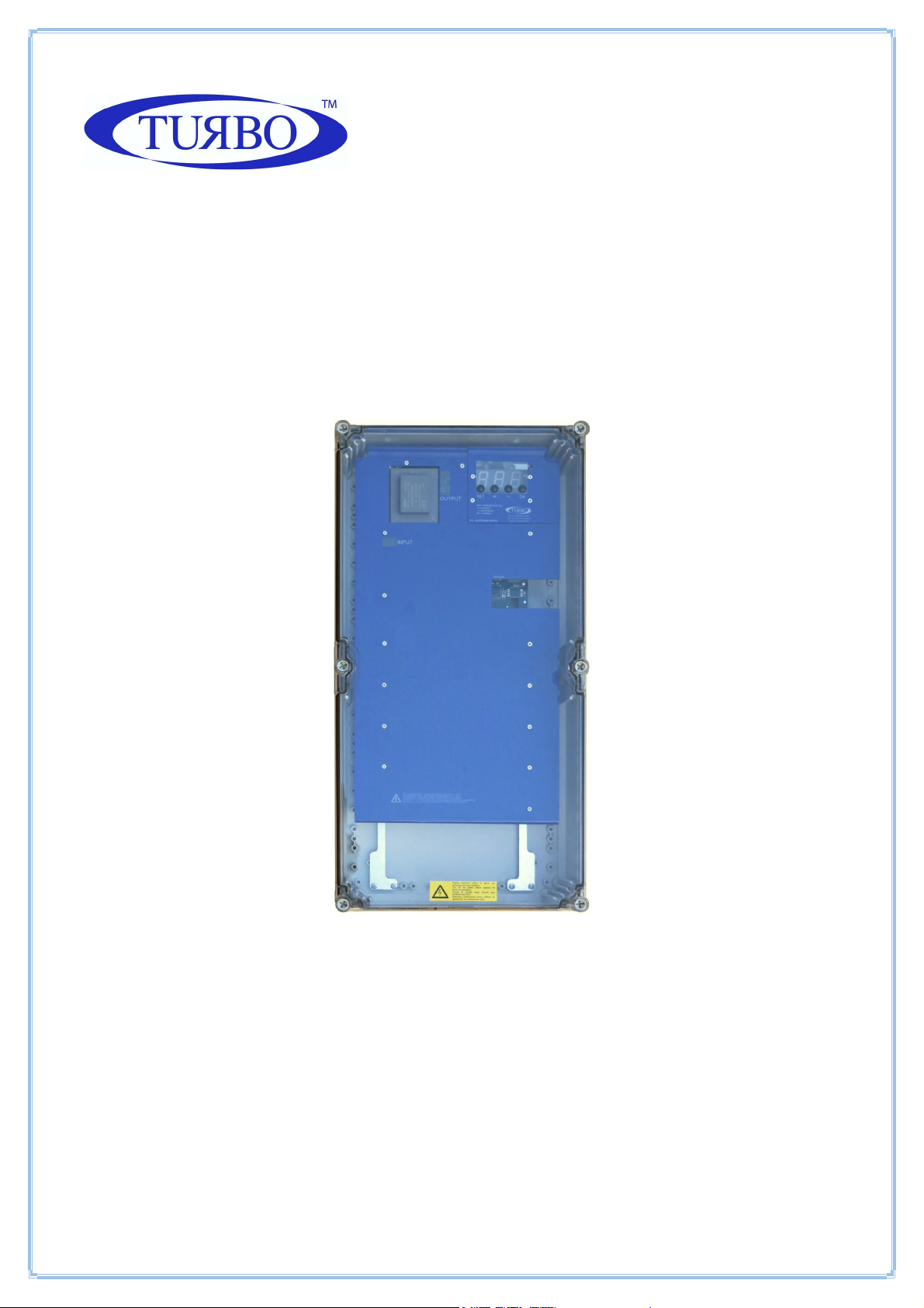
Elec tr on ic Control Sy st em s For Dus t Collectors
e-ma il : info@turbocontr ol s. it web : www.turbocont ro ls.eu
TEL. + +39 (0)362 5740 24 FAX ++3 9 (0 )3 62 574092
SEQUENCER
E1T
TURBO
s.r.l .
57 ÷ 99
OUTPUT CHANNELS
05 /0 5/2016
Manual R elease 1.00
Hard wa re Release 1. 01
User Manual
Page 2

1
General Description
Sequencer for controlling the pneumatic cleaning function of industrial dust
collection systems. The device has three output relays contacts and two digital
input contacts.
A large, bright display is provided for reading the filter obstruction level, the
active solenoid valves and any alarms in any moment.
Technical Specifications
Casing
Made of insulating, ABS base and polycarbonate lid.
Degree of protection to water and dust: IP65 (EN60529).
Shock resistance: IK07, impact energy 2 Joule (EN62262).
Performance of the Device
Dedicated software program, managed by the microprocessor, easy to set up
and consult, facilitates the use of the instrument also by users unfamiliar.
Led display with 7 segments, 3 digits (0.8” each).
Power voltage 115-230 Vac 50-60 Hz selectable by means of jumpers, must
also set with F05 (Optional 24 Vac/Vdc).
Output voltage 24Vdc, 24-115-230Vac selectable by means of jumper.
Three alarm relays.
Micro SD memory card for data storage, extractable for consultation.
Sampling is performed every 10 seconds, the time interval is editable.
Compressed air presence enable input.
External contact cleaning activation.
Manual solenoid valve activation.
Operating times expressed in seconds with selectable ranges for any
application.
Solenoid valve not working alarm.
Total and partial hour counter for maintenance.
Setting the current date and time associated with the archiving historical
data on the SD card, where are stored the detected values.
Page 3

2
Electric Specifications
War n i n g ! Re a d t he s e c t i on o n
Electric Power
115 Vac 50-60 Hz – 25W
230 Vac 50-60 Hz – 25W
24 Vac 50-60 Hz – 25W (optional)
24 Vdc– 25W (optional)
Selectable Output Voltage
230 Vac
115 Vac
24 Vac
24 Vdc
Inputs And Outputs Galvanically Insulated
Enable contact (remote cleaning enable).
Fan contact (post-cleaning).
The solenoid valves connected to the unit are normally closed.
The activation of a solenoid valves causes them to open and consequently let out
a jet of air.
ins t a l l a tio n b e f o re c o n nec t i n g
the d e v i c e.
Alarm Relays
The three alarm relays contain 2 clean contacts on terminals 4 ÷ 9 di J4.
Maximum permitted load: 3A @ 250Vac, 2A @ 24Vac, 2A @ 24Vdc
Fuse
1 x 1 A @ 115 Vac. 1 x 1 A @ 230 Vac.
1 x 3 A @ 24 Vac. 1 x 3 A @ 24 Vdc.
Working Temperature
from -10°C to 55°C
Storage Temperature
-20°C to 60°C
Timer Specifications:
Pulse Time (Valve Opening)
from 50 ms to 5 sec
Pause Time (Interval Between Valve Openings)
1 sec - 999 sec
Page 4

3
Installation Instructions / Notes and Warnings
Protect the device from direct exposure to sunlight.
Do not position the device near or directly in contact with sources of heat or
electromagnetic fields.
Connect the device to power lines other than those for operating motors or
other large power devices which could generate network interference.
Fix the device of a height of at least 60 cm from the ground.
Check that atmospheric conditions are safe before starting any operation on
the device.
For electric operations, always remove voltage, wait 30 seconds for the
inside capacitors to discharge before opening. At the end of the operations,
close the device to restore the correct degree of protection before powering
up.
Use flame-retardant cables with a minimum cross-section area of 0.25 mm2
for all control signals.
Use flame-retardant cables with a minimum cross-section area of 0.75mm²
to connect to the power supply.
Use flame-retardant cables with a minimum cross-section area of 1.5 mm2 to
connect to the indicating relays.
Any use not described in this user instruction manual or incorrect use of the
device may cause damage to the device or to the devices connected to it.
Furthermore, incorrect use or tampering with the device may cause injury.
Waterproofness of the casing is guaranteed when the flap is closed.
Make sure that rigid or flexible ducts used for wiring, if any, do not fill up
with water or other liquids.
Any holes made in the casing must be protected by accessories with degree
of protection equal to at least that of the sequencer.
Cut off power supply immediately if water is found in the casing.
Do not use the sequencer if you have not read or do not understand this manual.
Page 5
4
Display Keypad
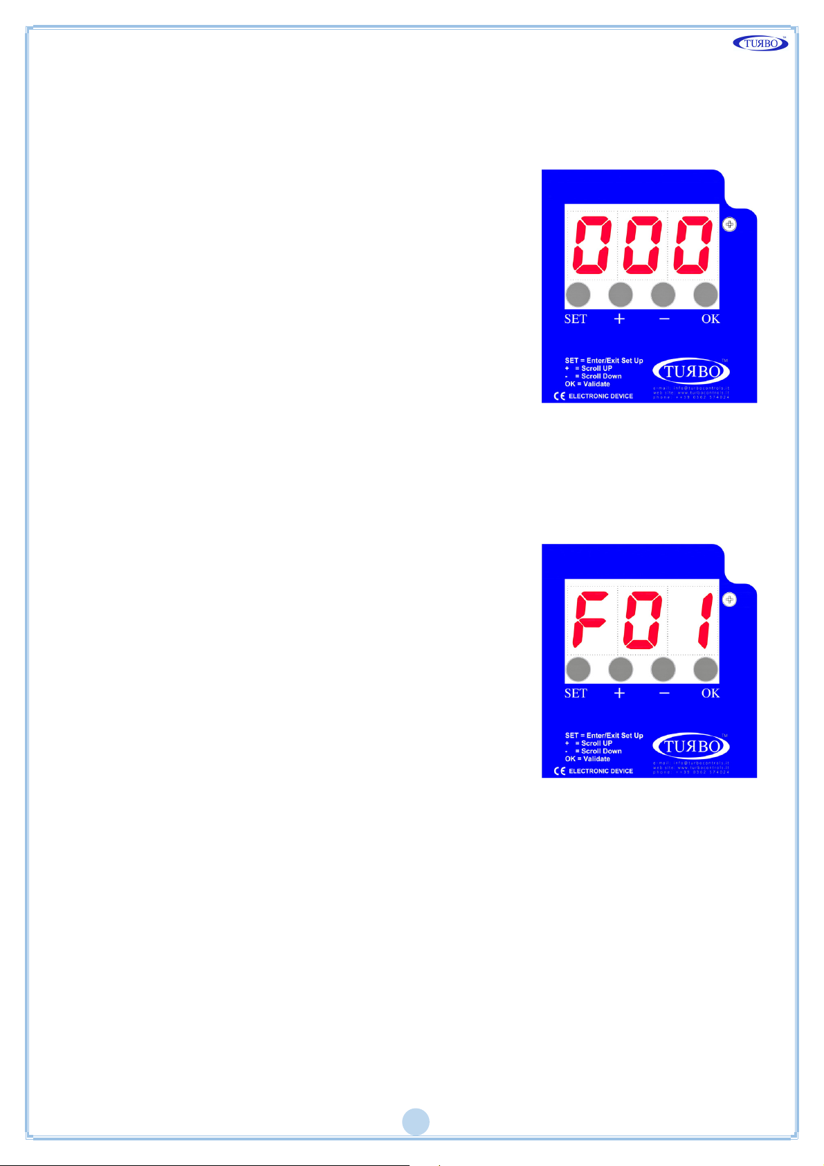
There are four round buttons on the front panel for controlling the device and
turning on the display as shown in the following figure.
The SET button enables to enter and exit the
programming menu, and activate the manual
solenoid test by selecting function F06.
The + and – buttons enable to scroll functions
from F01 to Fxx. After entering one of the Fxx
functions use the OK button to select and then +
and - increase or decrease the values.
The OK button is used to confirm data and reset
alarms.
If the + button is pressed during ordinary
operation, the activity hour meter is displayed.
The - Button pressed during the ordinary
operation, displays the counts partial hours of
activity.
If the Micro SD Card is inserted, the pressing of the OK button enables safe
removal of the card.
Menu Diagram
Press SET, the letter F flashes.
Press + and – to select the required function.
Press OK to confirm.
Increase or decrease the value of the parameter.
Holding down the + and - buttons to scroll
through all the functions until the end of the left
or right.
Press OK to confirm and exit.
Press SET again to exit programming mode.
Page 6

5
List of Functions
F02: Solenoid activation time.
Possible values: 0.05” – 5.00” step 0.01”.
Default = 0.20”.
F03: Washing pause time between solenoid valves.
Possible values: 001” – 999” step 1”.
Default = 20”.
F04: Number of connected outputs.
Possible values: 01 - 99
Depending on the version of the instrument, step 1.
F05: Output voltage setting.
Possible values: d24, A24, 115, 230.
Default = A24.
F06: Manual output activation.
Possible values: 1 – number of outputs set in F04.
Press SET to activate the set output.
F13: Number of post cleaning cycles after stopping the fan.
Possible values: 01 – 99 step 1.
Default = 01.
F14: Post cleaning mode pause time between solenoid valves (fan off).
Possible values: 001” – 999” step 1”.
Default = 10”.
F15: Maintenance frequency expressed in tens of hours.
(e.g.: 1=10h, 10=100h).
Possible values: 001 – 999 step 1.
Default = 100 (=1000h).
F16: Maintenance deadline alarm enable.
Possible values: 0 (disabled) – 1 (enabled).
Default = 0 (disabled).
F17: Maintenance hour counter reset.
Possible values: 0 (disabled) – 1 (reset).
Default = 0 (disabled).
No te : The maintenance hour counter
will be reset and the F17 parameter will be set back to 0 by setting F17 to 1.
F24: Setting the date on the internal clock.
Settable values: Day 1 – 31 d.
Month 1 – 12 п.
Year 00 – 99 y.
F25: Setting of the time for the internal clock.
Settable values: Hours: 0 – 23 HH.
Minutes: 0 – 59 пп.
F26: Exclusion of the valve in short circuit.
If set to 1 the valve shorted is excluded from the cycle.
Settable Values 0 (not excluded) - 1 (excluding)
Default = 0 (not excluded).
Page 7
6
move the AC/DC jumpers to DC. Jumper
If the jumper is in the correct position,
, set 115 or 230
the jumper is in the correct position,
, set 115 or 230
If the jumper is in the correct position,
minimum threshold or disconnected
Check correct connection of the solenoid
tion of the solenoid
Alarms
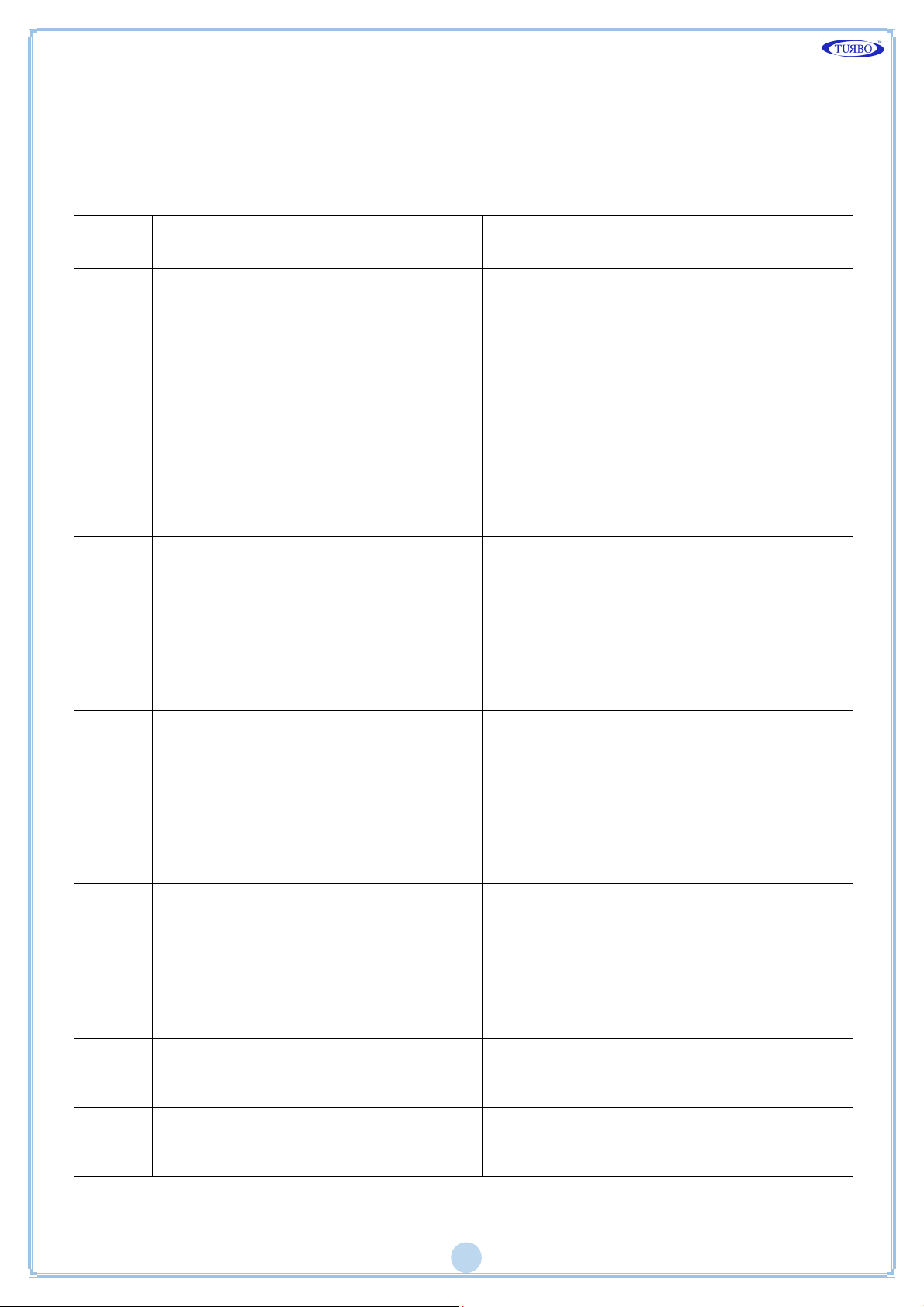
The unit runs a number of checks during the start-up cycle and during normal
operation. The possible alarms and respective solutions are shown in the
following table.
A. No.
E01
E02
E03
Description Action
F05 set to 24Vdc – AC jumper
detected
F05 set to 24Vac – DC jumper
detected
F05 set to 24Vac or dc. Voltage out
of range detected
- For 24Vdc, switch the device off and
see table next pages.
- For 24Vac, press OK, then press SET,
set the function F05 using “+” and “-”,
select A24 and press OK to confirm.
- For 24Vac, switch the device off and
move the AC/DC jumpers to AC. Jumper
see table next pages.
- For 24Vdc, press OK, then press SET,
set the function F05 using “+” and “-”,
select d24 and press OK to confirm.
- To use 24V valves, switch the device
off and move the output voltage
selection jumper to 24V. Jumper see
table next pages.
press OK, then SET, select the F05
function with “+” and “ -”
(as jumper) and press OK.
E04
E05
E06
E07
F05 set to 115V. Voltage out of
range detected
F05 set to 230V. Voltage out of
range detected
Solenoid valve current lower than
solenoid valve
Solenoid valve current higher than
maximum threshold
- To use 115V valves, switch the device
off and move the output voltage
selection jumper to 115V. Jumper see
table next pages.
- If
press OK, then SET, select the F05
function with “+” and “ -”
(as jumper) and press OK.
- To use 230V valves, switch the device
off and move the output voltage
selection jumper to 230V.
press OK, then SET, select the F05
function with “+” and “ -” , set a24, d24
or 115 (as jumper) and press OK.
valve and respective data. The alarm is
self-reset.
Check correct connec
valve and respective data. The alarm is
self-reset.
Page 8
7
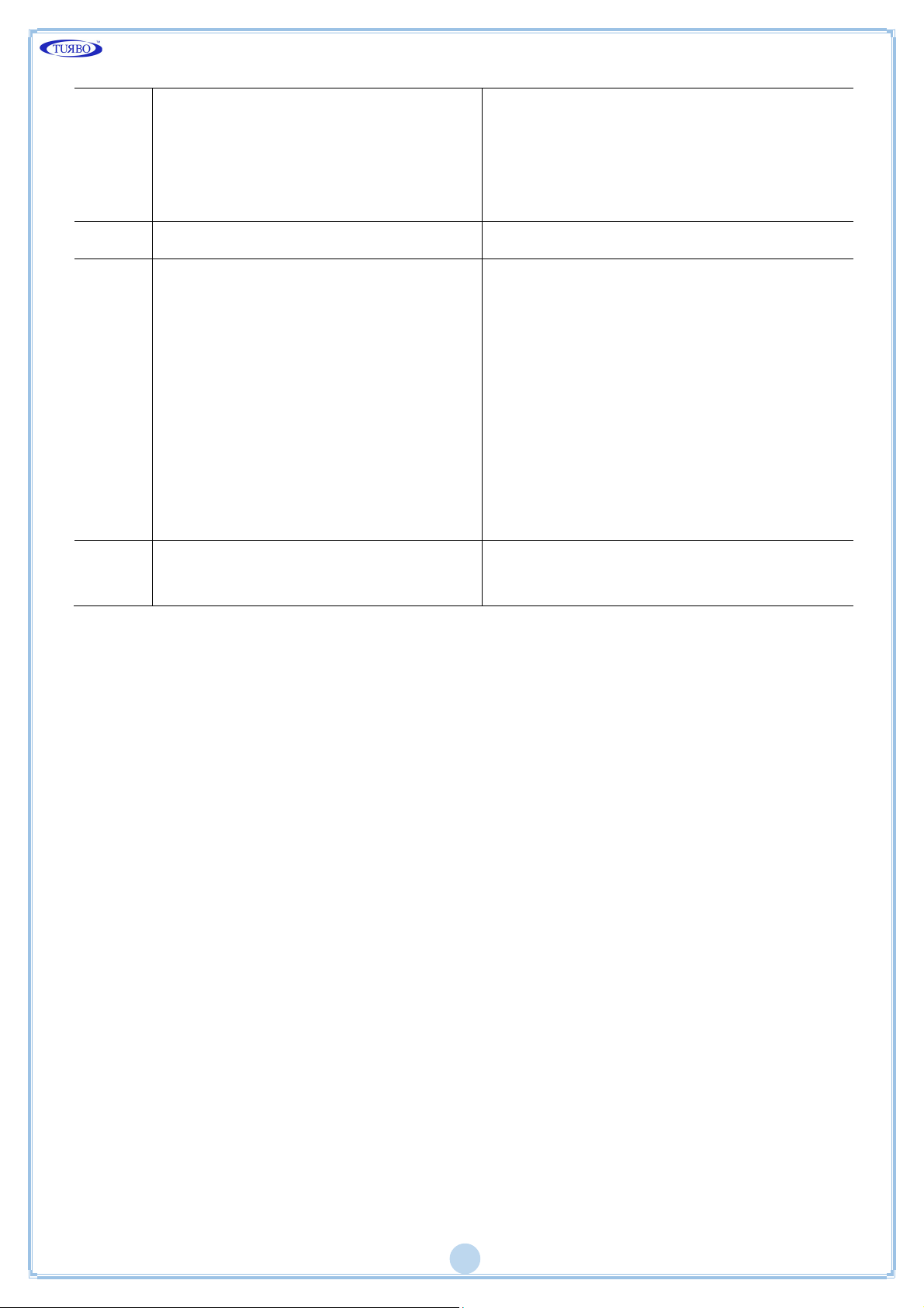
Output short circuit
alternates with the indication of the
device and then turn it back
on, after having verified the plant of the
alternates with the indication of the
Turn off the device and then turn it back
on, after having verified the plant of the
E08
The signaling of the code E08
interested output is shown as Uxx
where xx is the number of the
Turn off the
solenoid valves.
output.
E11 Maintenance deadline reached Carry out maintenance.
Indicates that a valve in short
circuit has been excluded from the
cycle.
The signaling of the code E14
interested output, is shown as Uxx
E14
where xx is the number of the
output.
solenoid valves.
An output is considered a short
circuit if not responding for 3
following activations.
An activation without error resets
the counting.
E20 Internal clock error.
Replace buffer battery (CR1632 3V
130mAh) and set current time and date
Page 9

8
Description Of Operation
The installed SW version and the symbol ---, meaning that coherence between
settings stored in E2Prom and the set jumpers is being checked, will appear on
the display when the sequencer is powered up. A corresponding error code will
appear in case of discrepancies between settings (see Alarms Table). Only editing
functions will be allowed on the unit. The operator may switch off the unit and
configure the jumpers correctly.
Symbol 0_0 will appear on the display if the test is entirely successful. The
following pages will then appear:
OFF if the enabling contact is open (14-15).
-0- if the enabling contact (14-15) is closed and the fan is off.
Operative mode
The device works as a programmable cycle sequencer. The connected outputs will
be activated at the programmable frequencies. The firing and pausing times can
be set on the configuration menu.
Cleaning Function With Fan Off (PCC)
This function allows to carry out one or more cleaning cycles (the number of
cycles is defined by F13) when the fan is off. The on or off state of the fan may
be determined by the state of the contacts 12-13 (contacts open = fan off) if
F11=0, or may be determined automatically (with F11=1) when the dP pressure
drops under the threshold defined in F12. The pulse time of the valves will always
be that defined in F02, while the pause time in this case is defined in F14.
The display alternately shows the number of the valve activated and the word PCC.
Number Of Output Selection
The number of outputs (solenoid valves) on which the sequencer will run the
cleaning cycle can be selected. Cleaning will be carried out in order from the first
to the last solenoid valve. The valves can be adjusted by the F04 function.
Fuse
A fuse which can be reset in case of need is located near the power terminal
board. Use a delayed fuse 5x20mm as shown in the table on next pages.
SD Memory Card
The Micro SD memory card slot is located on the bottom right of the control unit
under the polycarbonate lid.
The card is not supplied with the control unit. A card with a maximum of 32GB
can be used.
The card must be formatted FAT32, which is the format recognized by all devices
and operating systems.
Before removing the memory card, press the OK button with the control unit on,
wait for the cd (card) indication and the alternating flashing of the horizontal
lines of the third figure ≡. The card can now be safely removed. The Micro SD
Card connector is push-pull.
Press upwards and extract the card to remove it.
Page 10
9
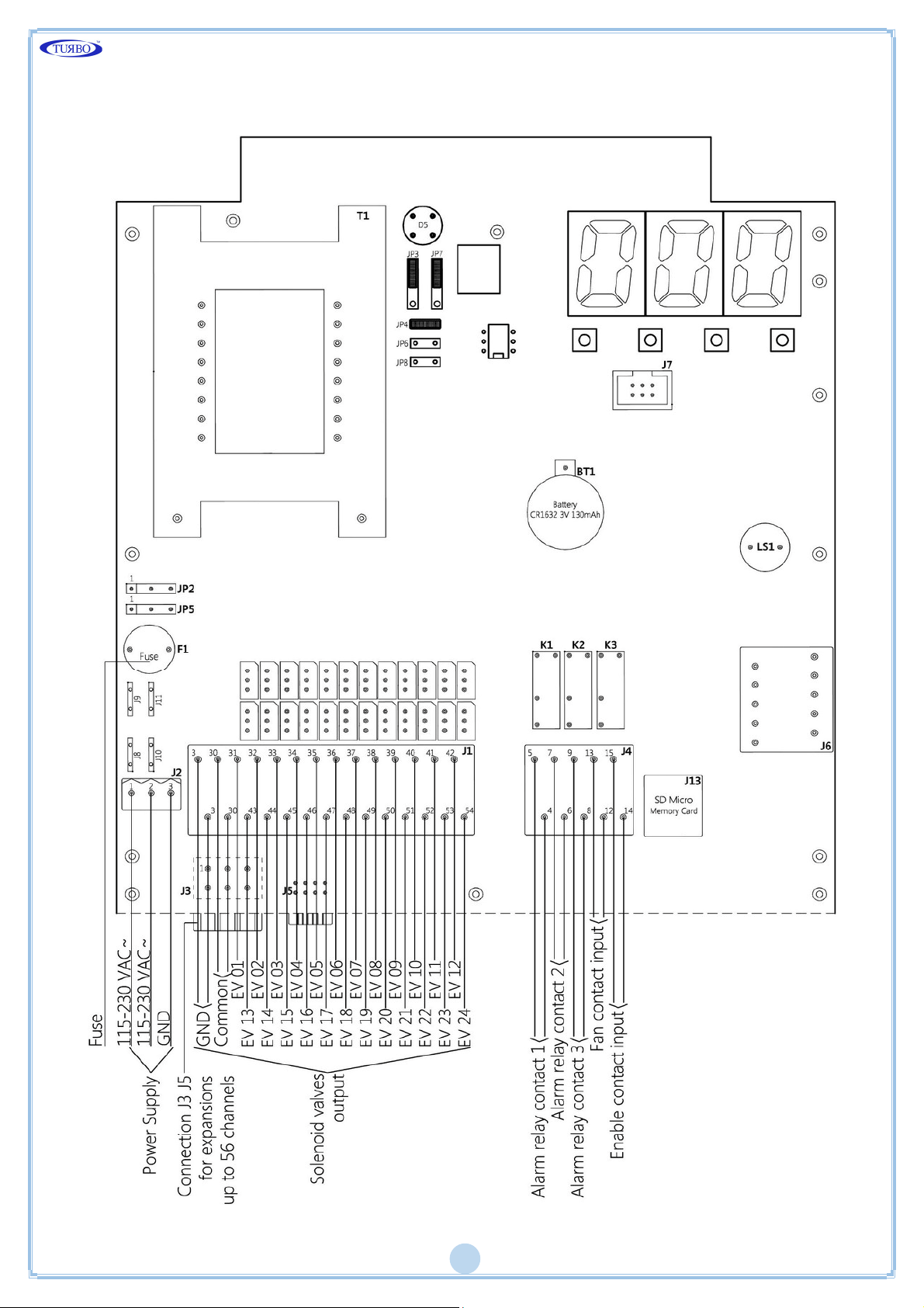
Connection Diagram Main Board
Page 11

10
Contacts And Relay Terminal Block J4
Enable contact input consensus 14.15 terminals.
Is used to activate the control unit remotely, it can be turned on and off
remotely.
The unit is supplied with a jumper on the two terminals 14:15, without it will
not turn on.
Fan contact 12.13 input terminals.
Indicated by the control unit that the plant has been started and is in operation.
The unit is supplied with a jumper on two 12:13 terminals to simulate the state
of the plant, as if the fan was turned on.
Alarm Relay K1 4.5 terminals.
The relay is normally closed, opens in case of alarms, and opens to the control
unit off in the absence of power.
The alarms that open the relays are:
Problem with solenoid valves E06-E08.
Maintenance interval has been reached.
If one of these occurs, the relay is activated.
Page 12
11
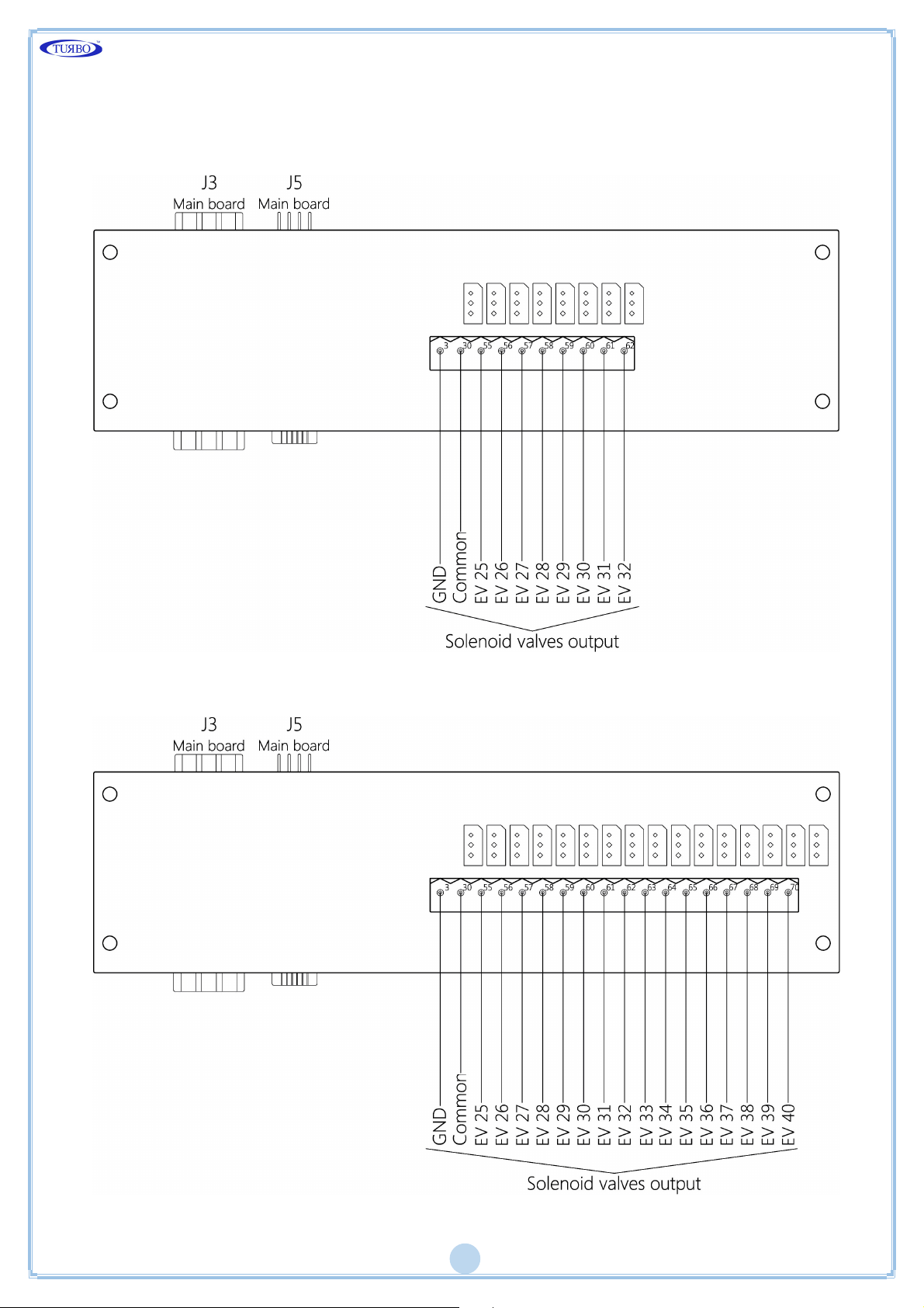
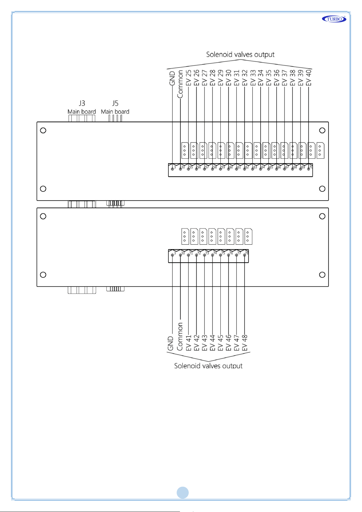
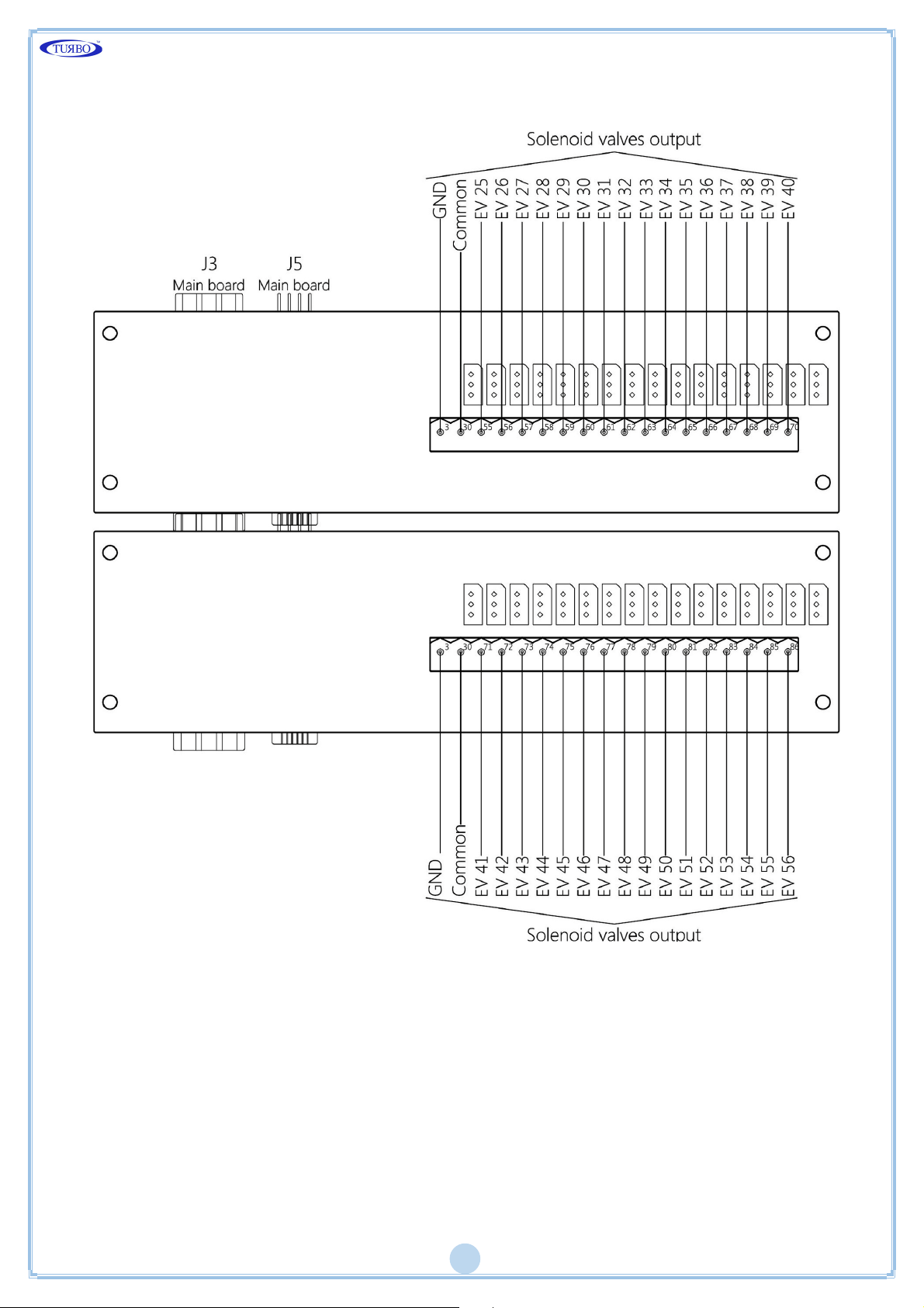
Connection Diagram Expansions
Expansion Up To 32 Channels
Expansion Up To 40 Channels
Page 13
12
Expansion Up To 48 Channels
Page 14
13
Expansion Up To 56 Channels
Page 15
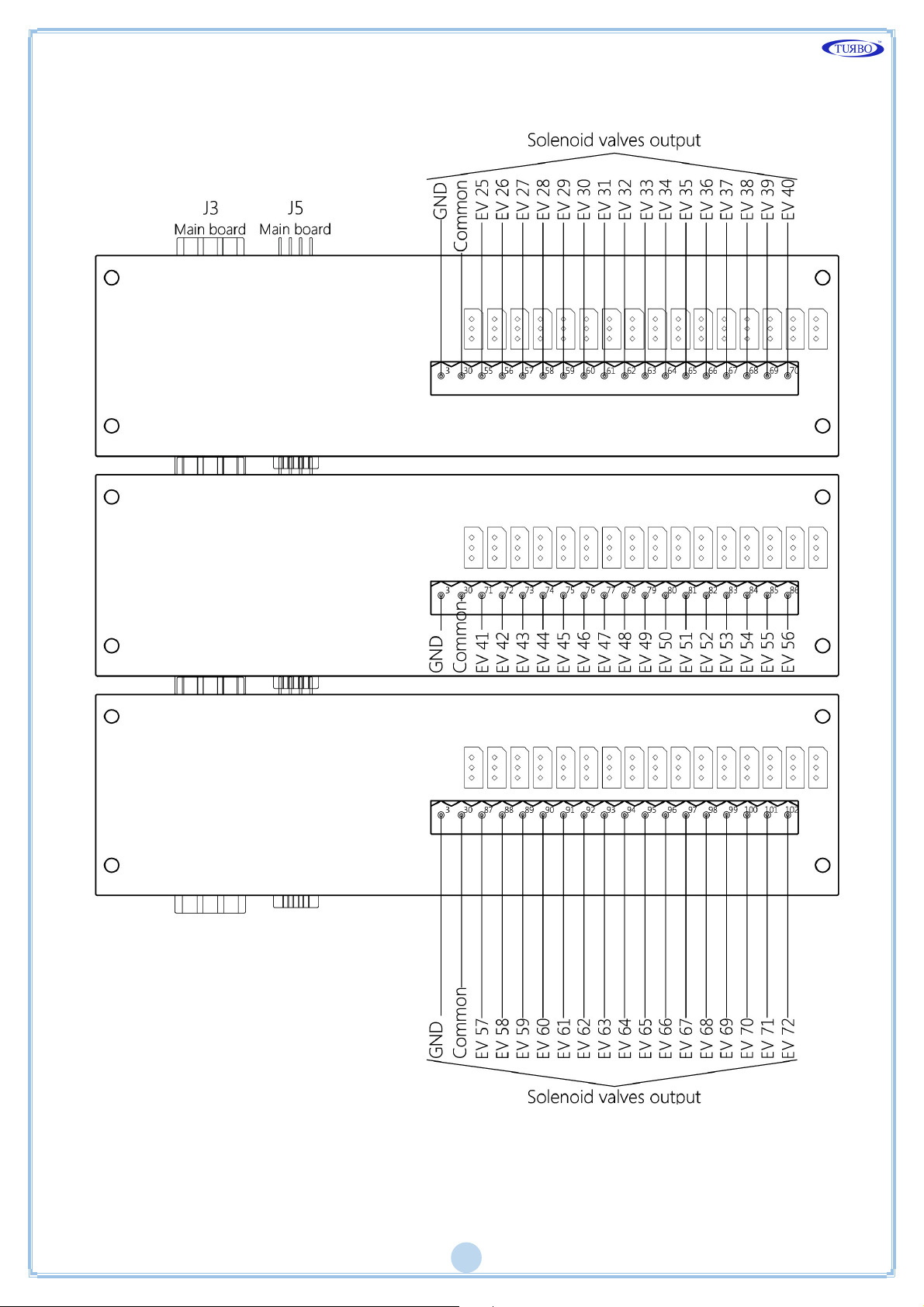
14
Expansion Up To 72 Channels
Page 16
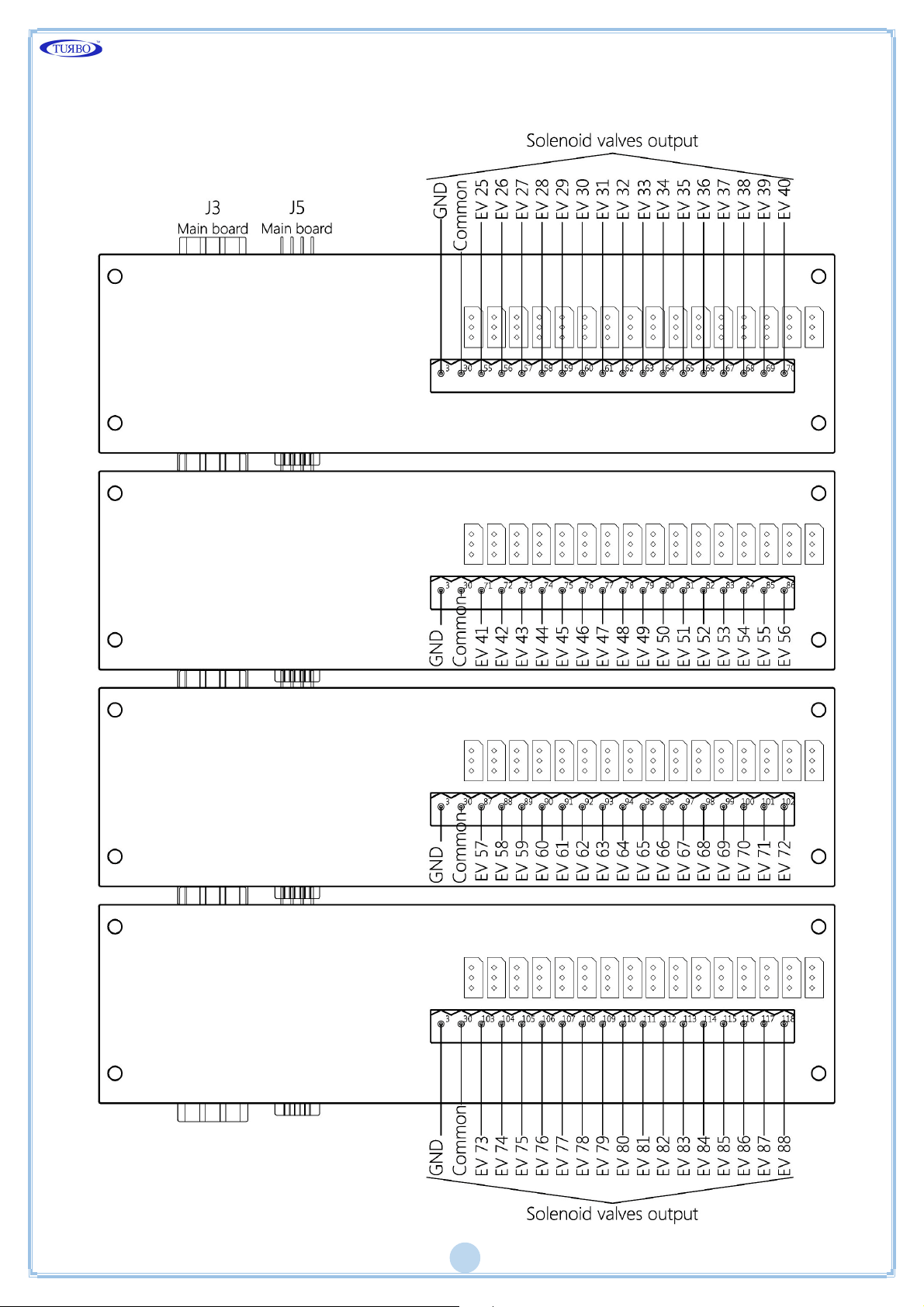
15
Expansion Up To 88 Channels
Page 17
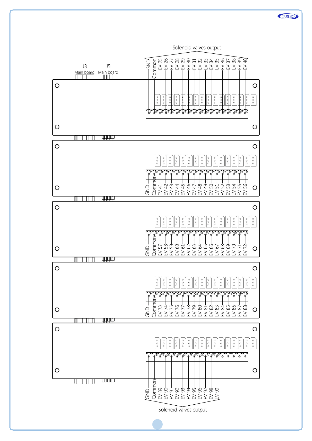
16
Expansion Up To 99 Channels
Page 18
17
Terminal Table
To access at the terminal blocks of the control board, unscrewing countersunk
screws of the cover panel blue.
Main Board
Terminal
Description Terminal
Description
01 Power Supply 115 230 Vac 45 Solenoid output 15
02 Power Supply 115 230 Vac 46 Solenoid output 16
03 Earth (GND) 47 Solenoid output 17
48 Solenoid output 18
03 Earth (GND) 49 Solenoid output 19
03 Earth (GND) 50 Solenoid output 20
30
30
Solenoid valve common
Solenoid valve common
51
52
Solenoid output 21
Solenoid output 22
31 Solenoid output 01 53 Solenoid output 23
32 Solenoid output 02 54 Solenoid output 24
33 Solenoid output 03
34 Solenoid output 04 04 Alarm relay contact 01
35 Solenoid output 05 05 Alarm relay contact 01
36 Solenoid output 06 06 Alarm relay contact 02
37 Solenoid output 07 07 Alarm relay contact 02
38 Solenoid output 08 08 Alarm relay contact 03
39 Solenoid output 09 09 Alarm relay contact 03
40 Solenoid output 10 12 Fan input
41 Solenoid output 11 13 Fan input
42 Solenoid output 12 14 Enable input
43 Solenoid output 13 15 Enable input
44 Solenoid output 14
Page 19
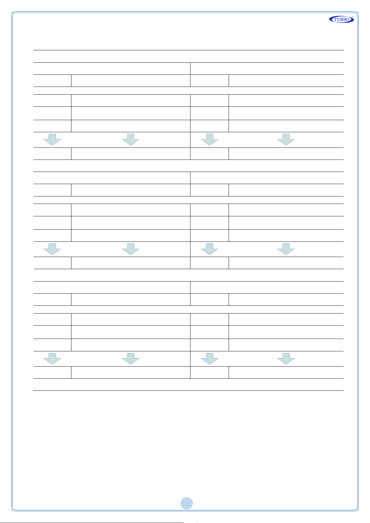
18
Expansion Boards
Expansion up to 32 channels Expansion up to 40 channels
Terminal
Description Terminal
Description
03 Earth (GND) 03 Earth (GND)
30
Solenoid valve common
30
Solenoid valve common
55 Solenoid output 25 63 Solenoid output 33
62 Solenoid output 32 70 Solenoid output 40
Expansion up to 48 channels Expansion up to 56 channels
Terminal
Description Terminal
Description
03 Earth (GND) 03 Earth (GND)
30
Solenoid valve common
30
Solenoid valve common
71 Solenoid output 41 79 Solenoid output 49
78 Solenoid output 48 86 Solenoid output 56
Expansion up to 64 channels Expansion up to 72 channels
Terminal
Description Terminal
Description
03 Earth (GND) 03 Earth (GND)
30
Solenoid valve common
30
Solenoid valve common
87 Solenoid output 57 95 Solenoid output 65
94 Solenoid output 64 102 Solenoid output 72
Page 20
19
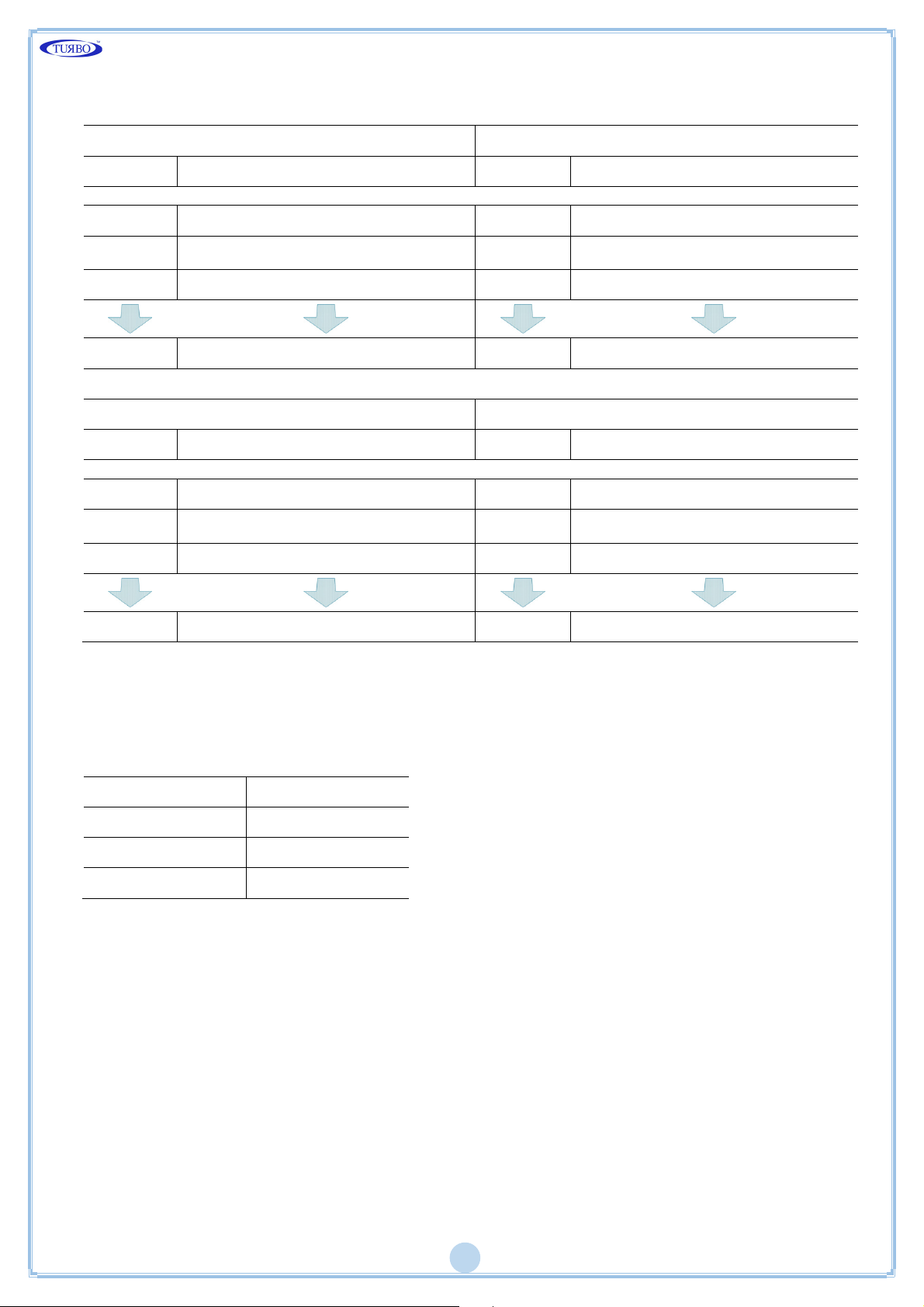
Expansion up to 80 channels Expansion up to 88 channels
Terminal
Description Terminal
Description
03 Earth (GND) 03 Earth (GND)
30
Solenoid valve common
30
Solenoid valve common
103 Solenoid output 73 111 Solenoid output 81
110 Solenoid output 80 118 Solenoid output 88
Expansion up to 96 channels Expansion up to 99 channels
Terminal
Description Terminal
Description
03 Earth (GND) 03 Earth (GND)
30
Solenoid valve common
30
Solenoid valve common
119 Solenoid output 89 127 Solenoid output 97
126 Solenoid output 96 129 Solenoid output 99
Fuse Table
Tensione Valore
230 V 1 A
115 V 1 A
24 Vdc / Vac 3 A
Page 21
20
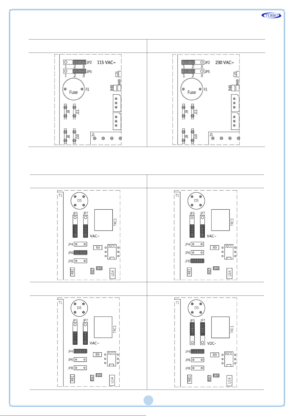
Jumper Configuration Power Supply
115VAC 230VAC
Jumper Configuration Output
115VAC 230VAC
24VAC 24VDC
Page 22
21
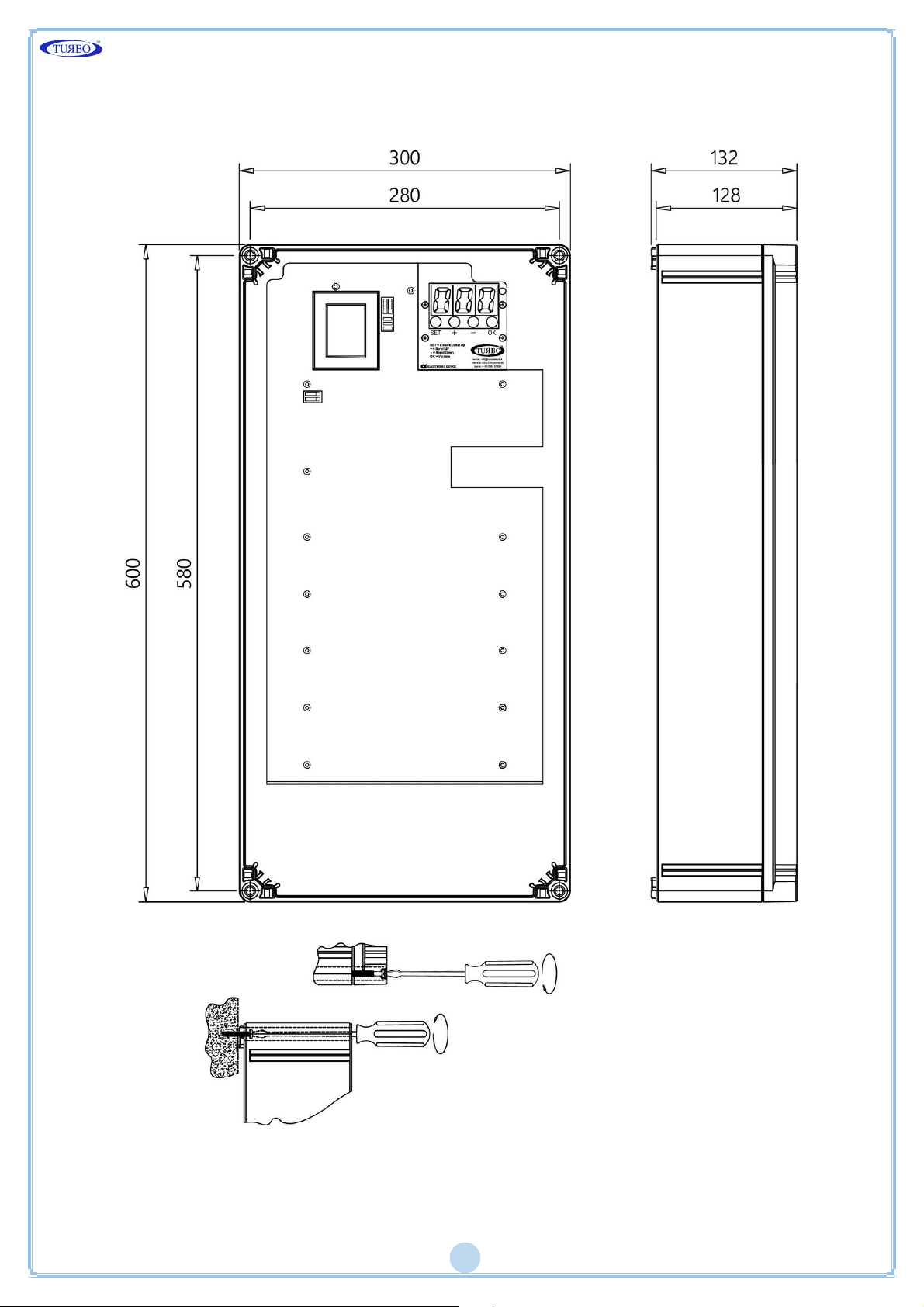
Installation And Casing Dimensions
Weig h t 4.8 K g
Page 23
22
Maintenance
Only the fuses, batteries and SD card can be replaced.
All other repairs must be done by the manufacturer.
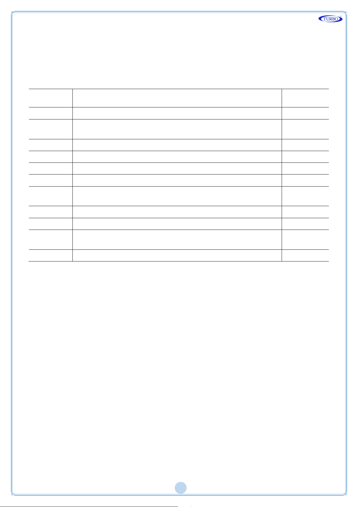
Default Settings
Function
Numb er
Description Set Value
F02 Solenoid valve activation time
F03
Washing pause time between solenoid valves in normal
cycle
F04 Number of outputs 1
F05 Tensione uscita: 24 Vdc, 24 Vac, 115 Vac, 230 Vac. 24 Vac
F06 Manual solenoid valve activation 1
F13 Number of cycles after fan stop 1
F14
Pause time between solenoid valves in cycle with fan
off
F15 Maintenance frequency in 10h (1=10h, 100=1000h) 100
F16 Maintenance deadline alarm on (1) or off (0) 0
F17
Maintenance hour counter reset: set 1 and confirm to
reset the maintenance hour counter
F26 Exclusion of valve in short circuit. 0
0.20”
020”
010”
0
Page 24
23
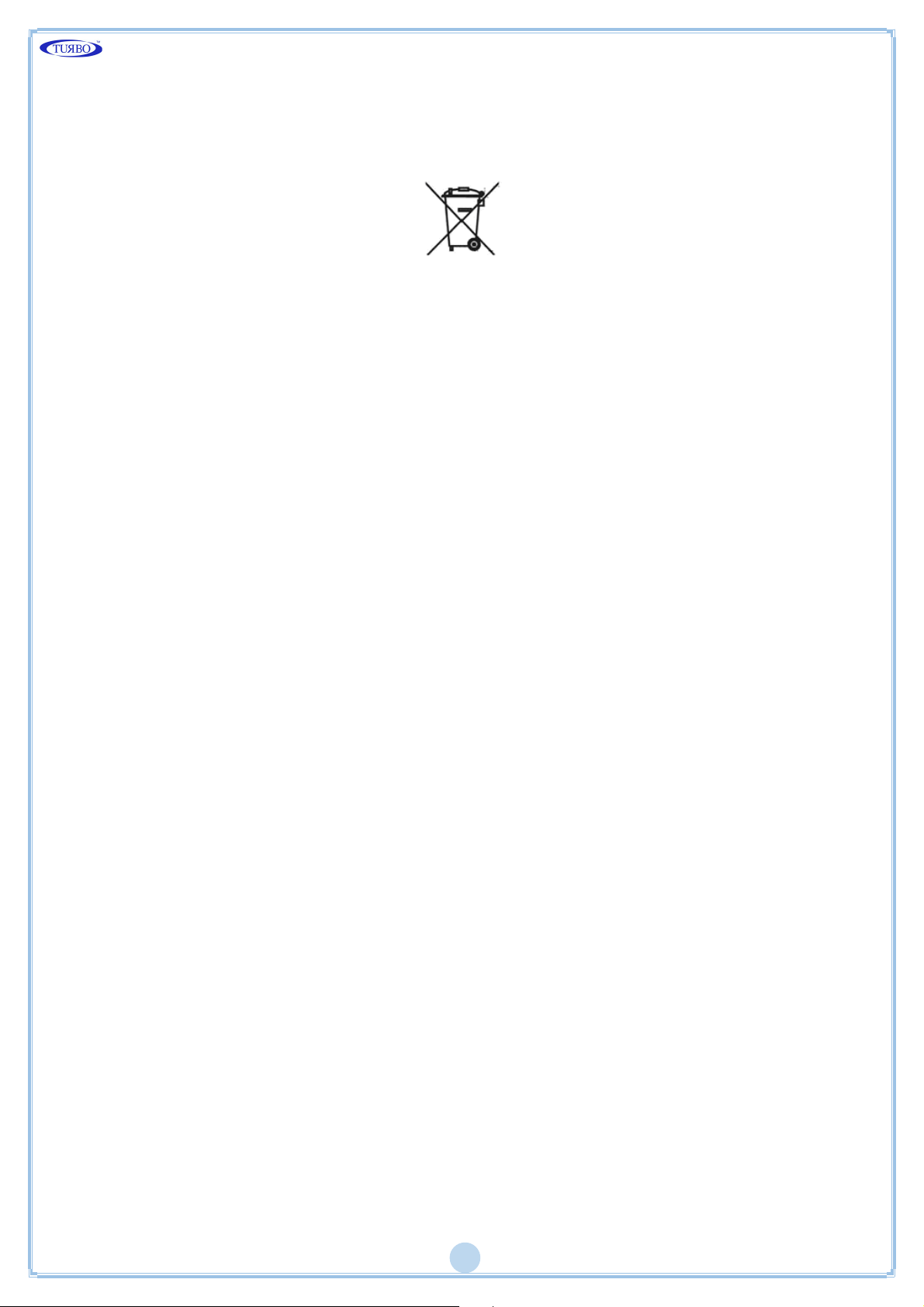
Disposal
Do not disperse in the environment after use. Dispose of the product according to
current regulations for the disposal of electronic equipment.
This device is used in a dust collector system and, therefore, it is part of a fixed
installation.
Warranty
The warranty has a duration of 2 years. The company will replace any
electronic component deemed defective exclusively at our workshop, except
in the presence of contrary agreements to be authorized by the company.
Exclusions From Warranty
The warranty is void in the case of:
Signs of tampering and unauthorised repairs.
Incorrect use of the equipment that does not comply with the technical data.
Incorrect electrical connections.
Failure to comply with the installation standards.
Use beyond EC standards.
Atmospheric events (lightning, electrostatic discharge), over voltages.
Clogged air connections. Damaged tubes.
Page 25
24
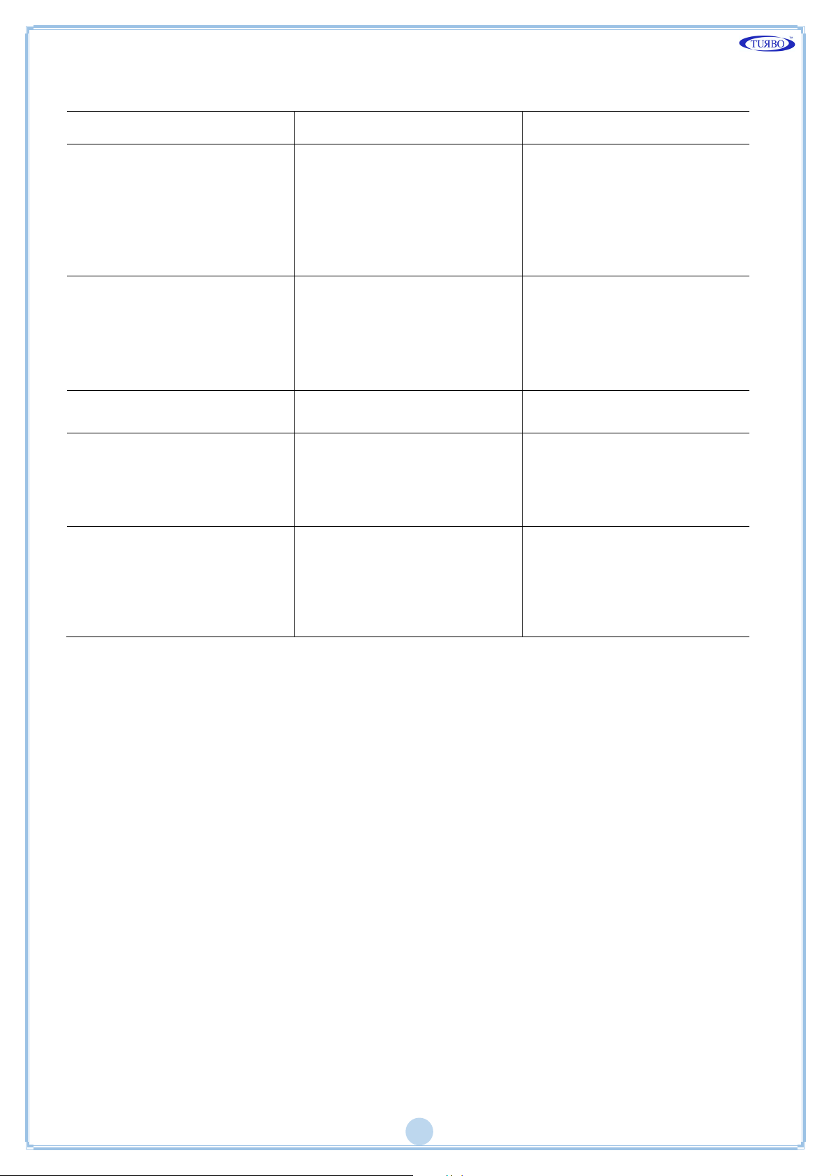
Problem Solution
FAQ
Fault Poss ible Cause Solution
The display does n ot light
up.
The outputs are not
activated.
Do alarm messages
appear?
Do the alarms fail to
activate signalling
devices?
Burnt fuse. Check the protection fuse
on the power voltage.
Check that the power
voltage is present and
compliant with that
required for the device
(terminal s 01 and 03).
Incorrect output voltage.
Wiri ng to solenoid valves.
Check that the uni t and
solenoid vale output
voltage agree.
Check wiring between
sequencer and solenoid
valves.
Check the alarm code with
the ta ble.
System wiri ng errors.
No p ower to alarm
devices.
The alarm d evices must be
powered by voltage
external to the sequencer.
Acti vating to open the
respective relay.
Does the sequencer
occasionally reset?
Check the there is no
filtered pulse load on the
power line (spot welding
machines, welding
machines, plasma cutters
etc.).
Install a filter on the
power line of the
sequencer, if need ed.
Page 26
25
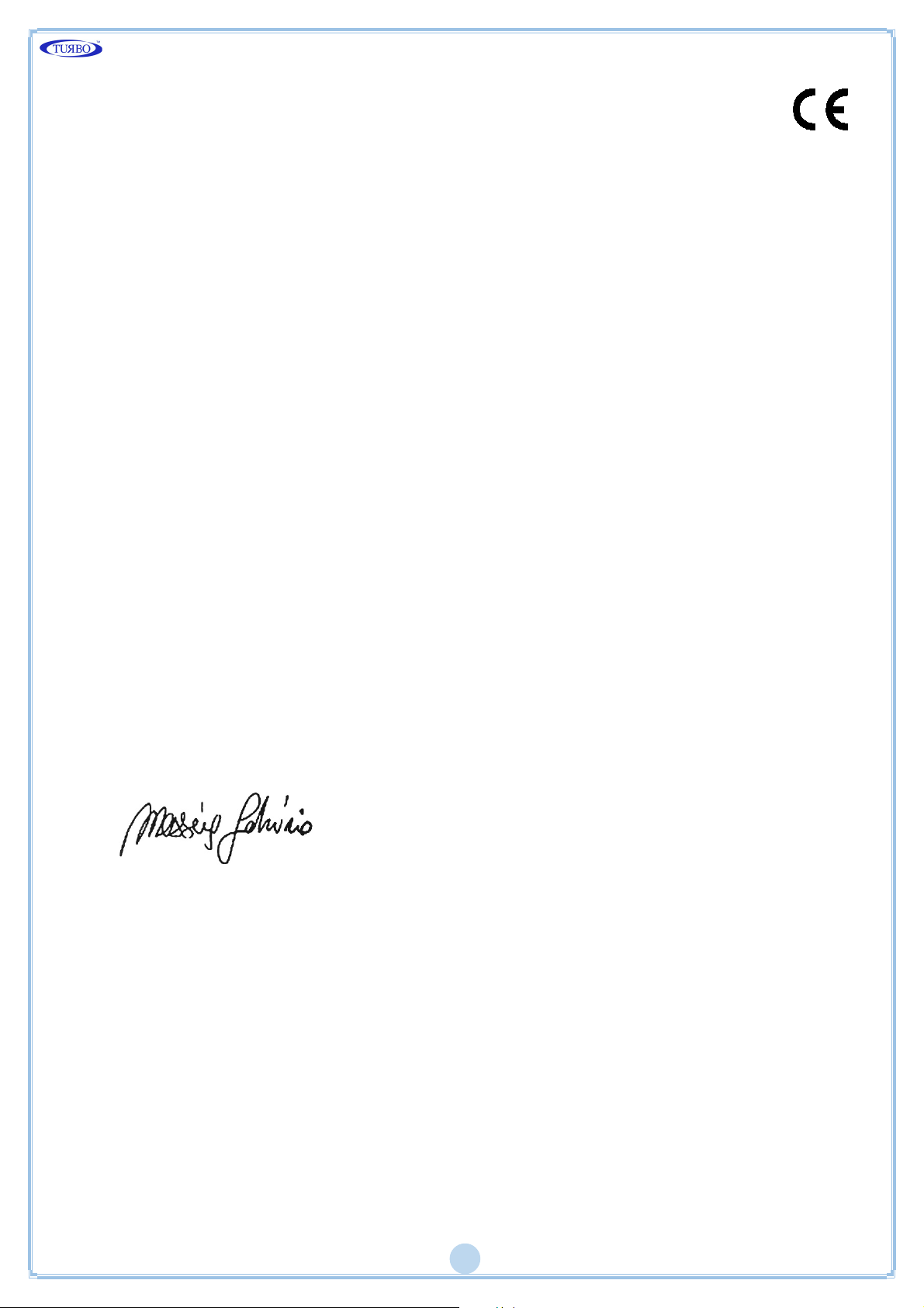
Declaration Of Conformity Of The Manufacturer
The Manufacturer:
TURBO SRL
The Manufacturer's Address:
Via Po 33/35 20811 Cesano Maderno (MB), Italy
Declares that:
Product Name:
Sequencer E1T
Product Options:
All
Complies with the following directives:
Machinery Directive 2006/42/EC 'Electromagnetic compatibility' compliant with
Harmonised European standards EN61000-6-2:2005 class B of EN61000-6-4:2001
Low Voltage Directive 2006/95/EC compliant with Harmonised European
Standards EN 60947-1:2004
A typical configuration of the product was tested.
Cesano Maderno, 05/05/2016
F. MESSINA (C.E.O.)
TURBO s.r.l.
Code And Serial Number
 Loading...