

Page 1
5.2.1 User Manual Isoforce
REV 5 01st July 2014 page 1 von 77
TUR Therapietechnik GmbH | Grubenstr. 20 | 18055 Rostock | Germany
Page 2

5.2.1 User Manual Isoforce
REV 5 01st July 2014 page 2 von 77
TUR Therapietechnik GmbH | Grubenstr. 20 | 18055 Rostock | Germany
Considerations Before the first Use
Before you start working with Isoforce, please be sure that you have carefully read and considered the
following points.
The installation of the system has been performed by trained staff. You can check if your
supplier is part of our authorised world-wide network by browsing our web site: www.iso-
force.com.
Isoforce should be operated by users with sufficient professional expertise. Our system
demands apart from familiarisation with the positioning, knowledge of all the clinical
considerations, as well as the possible applications. In the current manual we offer all the basic
information, but you should seriously consider further reading, as well as attendance in the
seminars held by our company.
Ensure that there are not cables that could be stepped over.
Remove any strong electromagnetic sources (preferably out of the room), as the working
conditions of the electronic circuits could be affected. Sources such as mobile phones should
not be placed on the device, and the patients should not carry them on. However, mobile
phones don’t affect the operation of Iso-Force in distance more than 1m.
In the unlikely event of system failure, please contact immediately with the authorised supplier
of your district. Do not attempt any service action by yourselves.
Isoforce offers remote assistant both for technical, as well as for application issues. This
demands wireless internet connection and you are strongly advised to install one if not any
available.
Despite the detailed information about the testing and rehabilitation procedures performed with
Isoforce, one should keep in mind that every patient should be treated specifically for his/her
pathology. Therefore, you should also take into consideration the unique characteristics of your
patients.
The positioning suggestions, as well as the testing protocols are not obligatory to use. On the
other hand we would be happy to see our clients to expand the applications beyond our own
suggestions. Isoforce is a powerful tool that gives you all the resources to do so.
All the info presented here, is based on scientific proven evidence and on published data. We
would be happy to give you our bibliography.
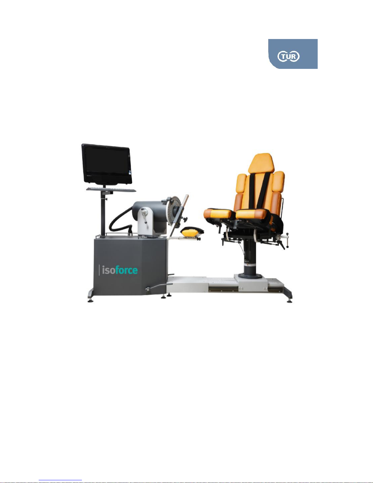
Before putting the patient on, it is suggested that you have the system in the position appearing
in the photo 1.1. This position is called the initial position.
For technical, application and marketing support please address either to your authorised supplier or
contact Iso-Force personnel through one of the following ways
Via e-mail:
Please consider that apart from these general considerations, there are Attention notes marked
with the symbol in the following paragraphs. Read carefully all of them.
Page 3

5.2.1 User Manual Isoforce
REV 5 01st July 2014 page 3 von 77
TUR Therapietechnik GmbH | Grubenstr. 20 | 18055 Rostock | Germany
Content
Chapter 1 - Clinical Considerations.................................................................................................. 6
1.1 About contractions................................................................................................................... 7
1.1.1 Concentric......................................................................................................................... 7
1.1.2 Eccentric............................................................................................................................ 7
1.1.3 Isometric............................................................................................................................ 7
1.2 Exercise Types........................................................................................................................ 7
1.2.1 Isokinetic Mode................................................................................................................. 8
1.2.2. The Passive Mode........................................................................................................... 9
1.2.3. Isometric Mode.............................................................................................................. 10
1.2.4 Isotonic Mode.................................................................................................................. 11
1.3 Contraindications for Resistance Training.......................................................................... 12
1.4 Additional Considerations..................................................................................................... 13
1.5 General Considerations before and after Testing............................................................... 13
1.6 Safety Considerations........................................................................................................... 13
Chapter 2 - Mechanical Overview.................................................................................................. 15
2.1 Dynamometer Assembly....................................................................................................... 16
2.1.1.Dynamometer Rotation.................................................................................................. 16
2.1.2.Dynamometer Tilt........................................................................................................... 17
2.1.3. Dynamometer Lifting..................................................................................................... 17
2.1.4 Range of Motion (ROM) Ring & ROM Mechanical Stops........................................... 17
2.1.5 Hand-Held Emergency Button....................................................................................... 18
2.1.6 Input Arm Adaptor.......................................................................................................... 18
2.1.7 Laser Pointer................................................................................................................... 18
2.2 Chair Assembly...................................................................................................................... 19
2.2.1 Seat Rotation.................................................................................................................. 19
2.2.2 Chair Transfer................................................................................................................. 20
2.2.3 Seatback Tilt................................................................................................................... 20
Page 4

5.2.1 User Manual Isoforce
REV 5 01st July 2014 page 4 von 77
TUR Therapietechnik GmbH | Grubenstr. 20 | 18055 Rostock | Germany
2.2.4 Bottom Seat Tilt –Height................................................................................................ 20
2.2.5 Bottom Seat For/Aft........................................................................................................ 21
2.2.6 Cervical Support............................................................................................................. 21
2.2.7 Stabilization Straps......................................................................................................... 21
2.2.8 Hand Grips...................................................................................................................... 21
2.2.9 Receiving Tubes............................................................................................................. 21
2.3 Adapters................................................................................................................................. 23
2.3.1 Dynamometer and Chair Attachments/Adapters........................................................ 23
Chapter 3 - Set Up / Positioning / Operation................................................................................. 26
3.0 Set Up and Positioning......................................................................................................... 27
3.1 Ankle....................................................................................................................................... 28
3.1.1 PlantarFlexion/DorsiFlexion........................................................................................... 28
3.1.2 Inversion/Eversion......................................................................................................... 32
3.2 Hip............................................................................................................................................ 35
3.2.1 Hip Abduction – Adduction (Lying on Side).................................................................. 35
3.2.2 Hip Extension – Flexion (Supine).................................................................................. 37
3.2.3 Hip Internal – External Rotation .................................................................................... 39
3.3 Knee Joint.............................................................................................................................. 40
3.3.1 Knee Extension – Flexion.............................................................................................. 40
3.3.2 Knee Internal-External Rotation.................................................................................... 43
3.4 Shoulder................................................................................................................................. 46
3.4.1 Flexion – Extension (Supine)......................................................................................... 46
3.4.2 Adduction – Abduction (Laying) .................................................................................... 48
3.4.3. Shoulder Horizontal Adduction/Abduction, Supine..................................................... 51
3.4.3 Internal External Rotation Patterns............................................................................... 53
3.5 Elbow...................................................................................................................................... 56
3.5.1 Elbow Extension – Flexion............................................................................................. 56
3.5.2 Pronation – Supination................................................................................................... 58
3.6 Wrist........................................................................................................................................ 60
Page 5

5.2.1 User Manual Isoforce
REV 5 01st July 2014 page 5 von 77
TUR Therapietechnik GmbH | Grubenstr. 20 | 18055 Rostock | Germany
3.6.1 Flexion / Extension......................................................................................................... 60
3.6.2 Radial / Ulna Deviation .................................................................................................. 62
Chapter 4 - Normative Data............................................................................................................ 64
1 Normative Data Lower Limb.................................................................................................... 65
4.2 Normative Data Upper Limb................................................................................................. 66
Chapter 5 - Parameters................................................................................................................... 67
Chapter 6 - Cleaning and Maintenance......................................................................................... 70
6.1 Cleaning................................................................................................................................. 71
6.1.1 Data Station.................................................................................................................... 71
6.1.2 Adapters.......................................................................................................................... 71
6.1.3 Upholstery....................................................................................................................... 71
6.2 Maintenance .......................................................................................................................... 71
Chapter 7 - Technical Specifications............................................................................................. 72
7.1 Laser Pointer.......................................................................................................................... 73
7.2 Dynamometer Performance Specifications:........................................................................ 73
7.3 Operation Specifications....................................................................................................... 73
7.4 Data Station........................................................................................................................... 73
7.5 Mechanical Specifications.................................................................................................... 73
7.6 Electrical Requirements........................................................................................................ 74
7.7 Classification.......................................................................................................................... 74
7.8 Operating Conditions............................................................................................................ 74
7.9 Transport and Storage Conditions....................................................................................... 74
7.10 Technical Description.......................................................................................................... 74
7.11 EMC Informations................................................................................................................ 74
Chapter 8 - Labelling....................................................................................................................... 75
8.1 Device Label.......................................................................................................................... 76
8.2 Laser Labeling....................................................................................................................... 77
8.3 Symbol Explanation............................................................................................................... 77
Page 6

5.2.1 User Manual Isoforce
REV 5 01st July 2014 page 6 von 77
TUR Therapietechnik GmbH | Grubenstr. 20 | 18055 Rostock | Germany
Chapter 1 - Clinical Considerations
Page 7

5.2.1 User Manual Isoforce
REV 5 01st July 2014 page 7 von 77
TUR Therapietechnik GmbH | Grubenstr. 20 | 18055 Rostock | Germany
1.1 About contractions
1.1.1 Concentric
Concentric, when literally translated, means towards the middle. This type of contraction occurs when
the tension generated within the muscle is sufficient to overcome a resistance (in most cases at least
gravity) to move a body segment (or the attachment of the muscle on that body segment) towards
another segment (or the origin of the muscle in question) or vice versa. This type of contraction is
dependent on one end of the muscle having more stability than the opposite end. The term dynamic
shortening seems to be a more appropriate way of describing concentric contractions.
1.1.2 Eccentric
Eccentric, when literally translated, means away from the middle. Whenever a muscle lengthens it
generates a contractile force meaning all movements in the body occur with some muscular activity
(this is absolute). The term lengthening is actually misleading as in most instances the muscle does not
actually lengthen. In reality it returns from its shortened condition to its normal resting length. In most
instances in which muscles contract eccentrically they actually act as a brake or resistive force against
the moving force of gravity or other external force (like a weight). This work is often referred to as
negative work for reasons I do not understand. Eccentric actions produce greater loading of the elastic
musculoskeletal components and are used during many dynamic movements (like walking down stairs
or hitting a ball). As the majority of muscle tears are thought to occur during eccentric motions
improvements in this performance may be beneficial for injury prevention. However, eccentric motions
produced by active dynamometers are not considered to be like those seen during functional activities.
Short and rapid eccentric motions are normally produced during daily and sporting activities,
isokinetically this is not seen as the movements are usually long and through full range of motion.
1.1.3 Isometric
Isometric, when literally translated, means equal length. When a muscle is contracted without any
appreciable change in length this is referred to as isometric contraction. This term is abused by
researchers, exercise scientists and physiotherapists to describe many different situations in which a
muscle is contracted but cannot be said to be acting either concentrically or eccentrically.
1.2 Exercise Types
Different type exercise programs are available that apply Davis’ Law to produce better integrity of the
joint. There are three basic types outlined: isometric, isotonic, and isokinetic. Isotonics can be divided
into a concentric (positive) movement, an eccentric (negative) movement, and variable resistance. The
isokinetic type can also be divided into a concentric or eccentric movement or both.
These types of exercises can be defined and contrasted in terms of the speed of movement and the
resistance applied. In isometrics, we know that the speed of movement is zero and the resistance is
fixed. In isotonics, on the other hand, the speed is variable, generally fluctuating around 60° as
demonstrated in weight lifting where there often is a slowing of movement at the weak points in the
range of motion (ROM). The resistance in isotonics is fixed (the amount of weight lifted). In isokinetics,
Page 8

5.2.1 User Manual Isoforce
REV 5 01st July 2014 page 8 von 77
TUR Therapietechnik GmbH | Grubenstr. 20 | 18055 Rostock | Germany
the speed is fixed but the resistance is variable. Thus we can see that isokinetics is the opposite of
isotonics.
These types of exercises can be designed in musculoskeletal rehabilitation to optimize joint integrity by
strength. Strength has been defined as the “maximum voluntary force exerted in a single muscular
effort.”
Mechanical muscle-strength testing has played a key role over the years in the prescription of exercise
programs, the identification of the sequence of orthopedic disabilities, and the prevention of
musculoskeletal injuries. The evaluation of strength is crucial in determining overall musculoskeletal
fitness. Indeed, the lack or impairment of strength can seriously affect an individual’s success in any
musculoskeletal endeavor.
“Active exercise may be either static or kinetic. Static (isometric) exercise is performed without
producing joint motion. The muscle exercised maintains a fixed length. Kinetic (isotonic) exercise is
performed to produce joint movement. Contracting muscles shorten, causing movement of the joint at
which they are attached. Isokinetic exercises produce joint motion at a controlled rate of speed.
Concentric contraction occurs when a muscle is contracted from an extended to a shortened position.
Eccentric contraction occurs when a tense-shortened muscle lengthens. Power is the ability to release
muscular work as a function of time. Endurance is the ability of muscles to perform work by holding a
maximum contraction for a given length of time or by continuing to move a submaximal load.”
Iso-Force offers a wide range of operation modes. Below you can find information regarding main
clinical implications and considerations for each one of them.
1.2.1 Isokinetic Mode
In the concentric isokinetic mode, the dynamometer acts to control velocity, allowing the subject to
accelerate up to, but no higher than, the maximum speed value selected for each direction of shaft
rotation (accommodating resistance). The subject may freely decelerate or change direction of
movement at any point within the range of motion.
In the eccentric isokinetic mode the dynamometer responds to torque exerted by the patient by moving
in the opposite direction of the applied torque.
The Isokinetic mode may be used at higher speeds in order to simulate functional or sports activities. It
can also be used early on in the rehabilitation process to prevent compression and translation in the
knee joint. Different bi-directional velocities can be set. Thus you can simulate physical activities. By
choosing different type of contraction con/ecc or ecc/con, you can isolate but also more precisely
simulate every functional patterns.
Keep in mind that it is possible to generate 30-40% more force eccentrically than concentrically. In
concentric isokinetic contractions the lower the velocity the higher the muscular tension. Therefore, the
torque produced is much higher. On the contrary in eccentric exercise, the force increases as the
velocity of contraction increases (up to a certain point)
Page 9

5.2.1 User Manual Isoforce
REV 5 01st July 2014 page 9 von 77
TUR Therapietechnik GmbH | Grubenstr. 20 | 18055 Rostock | Germany
Eccentric contraction involves a “training” of the non-contractual elements of muscle so that the muscle
“learns” to function in a higher force environment. It has been suggested that eccentric exercise
produces the greatest force in the least amount of time, while it is said to enhance muscle force
production and are less costly metabolically than concentric contractions
There are a few things to consider when setting the angular velocity in isokinetic mode: Exercising
every 30 degrees/second will help you overcome the specificity of strength gain. Higher velocities are
ideal for endurance gains without putting too much pressure on joints.
The Reactive Eccentric mode may be used to work on proprioception. When torque limits are set, the
subject must exert at least one-tenth of the torque limit to keep the shaft moving. If the subject exceeds
the limits, the unit will stop.
1.2.2. The Passive Mode
The Iso-Force Passive mode allows the dynamometer to provide continuous motion at constant
velocity, with direction changes occurring only when range of motion limits are reached.
In Passive mode, the dynamometer initiates motion when the Start button is pressed, requiring no
active participation by the subject.
CPM acts to reduce blood and fluid accumulation in and around joints that have been traumatized or
undergone surgery. In this way, CPM is useful in avoiding the development of subsequent joint stiffness
in the first few hours or days. Avoiding stiffness in the early stages minimizes its chances of progression
to fibrosis of the joint and establishment of contracture. Long-term benefits, however, are predicated on
preventing the accumulation of blood and/or edema fluid in the joint or periarticular tissues. This is
accomplished by the immediate application of a full range of passive motion on CPM, or by briefly
elevating and splinting the limb in a position that keeps the periarticular tissues stretched before
instituting a full range of passive motion on CPM. In the event that the patient is temporarily prevented
from using the machine due to other medical or technical factors (if, for example, the machine breaks
down) and periarticular swelling does occur, it must be reduced by alternately stretching the joint at its
limits of flexion and extension to work the fluid out of the periarticular region.
CPM is indicated to prevent stiffness and to maintain motion obtained at the time of surgery,
particularly following joint replacement, synovectomy, contracture release, excision of heterotopic
ossification, and fixation of intra-articular fractures. This is particularly true for joints that were stiff
preoperatively. It is relatively contraindicated if the soft tissue constraints (ligaments) are insufficient, if
the joint is unstable, or if rigid fixation of fractures has not been attained. By following these guidelines
and adhering strictly to the principles of CPM use, one will increase the chances of obtaining maximum
range of joint motion following trauma or surgery. It would be anticipated that proper application of CPM
would, indeed, be cost effective, because it would decrease the need for physical therapy and joint
manipulation under anesthesia, and later rehabilitation or surgical intervention to treat stiffness.
The Passive mode may be used to exercise or test isokinetically. Subjects that cannot meet the speed
will be passively moved through this portion of the range. The mode can also be used to stimulate joint
and muscle mechanoreceptors to improve proprioception.
Page 10

5.2.1 User Manual Isoforce
REV 5 01st July 2014 page 10 von 77
TUR Therapietechnik GmbH | Grubenstr. 20 | 18055 Rostock | Germany
Finally, the Passive mode may be used for passive stretching. When this is performed, the torque limits
in each direction should be set low and the time delay at least at the edge in interest should be set high.
It is not necessary to have a wide range of motion.
Attention! Ensure torque limits are set to overcome limb weight.
1.2.3. Isometric Mode
In this mode, the dynamometer maintains zero velocity at any selected point in the range of motion.
Significant change in joint angle and overall muscle length does not occur.
The interruption of normal function from musculoskeletal injury and immobilization leads to a loss of
strength not only in the muscles of a damaged extremity but also in those of uninjured extremities. This
loss can be largely avoided with the proper use of isometric exercise. In most cases, uninjured body
parts can be exercised even on the first day of immobilization of the injured part. The injured and
immobilized extremity can be isometrically tensed and thus exercised while still in a cast or in a splint
after the immediate pain has subsided. In this way, much of the potential loss of muscle strength can be
avoided. The muscle atrophy already setting-in can also be countered. A primary advantage of
isometric exercise in musculoskeletal rehabilitation lies in the opportunity for localized muscle exercise
without moving involved joints.
Strength increases more rapidly in isometric than in dynamic exercises. On the other hand, strength is
also lost more rapidly after cessation of exercise. A primary disadvantage is that the muscular
coordination necessary for many types of musculoskeletal activities is not integrated in this exercise,
which is why isometrics must, in time, be combined with dynamic exercises in the treatment of various
musculoskeletal conditions. Isometric exercise places great compression stress on the joint; thus,
people with arthritic conditions should not participate in intense isometric contractions. Also, people in
danger of heart attacks should not engage in intense isometric training because of the danger of
compression narrowing blood vessels.
There are thus unique advantages to isometrics due to the fact that they do not move a joint and
therefore can be used early in a rehabilitation program. Static strength increases, and atrophy retards.
Most other advantages to isometrics focus around the lack of special facilities and equipment needed to
perform them.
Disadvantages must also be carefully understood. A major disadvantage is a limited overflow of strength
development. Approximately 20° of overflow from the angle of application occur: strength gains will be
noticed for 10° on each side of the application. This is a small amount, and therefore, realistically,
isometric exercise at one point in a plane will not increase strength at another point in the plane. Other
problems also exist with isometrics such as difficulty with patient motivation, minimal gains of endurance,
and lack of eccentric workloads.
When we apply an isometric contraction, the general rule to follow is known as the “Rule of Tens,”
wherein we build tension in 2 seconds, hold the desired tension for 6 seconds, and then gradually relax
tension in 2 seconds. Applying this to isometrics, we usually recommend a 10-second contraction, 10
seconds of rest between each contraction, ten repetitions, and ten sets at ten different angles in the
ROM.
Page 11

5.2.1 User Manual Isoforce
REV 5 01st July 2014 page 11 von 77
TUR Therapietechnik GmbH | Grubenstr. 20 | 18055 Rostock | Germany
One should exercise at various angles in the ROM because of the limited physiologic overflow. If we
apply isometrics only at one point, there is approximately a 10° overflow on each side. How then would
we apply isometrics when there is a painful point in an arc of motion? We would exercise at every 20°
using the Rule of Tens throughout the range of motion, beginning at 10° on each side of the painful
position. Thus we would get a physiologic overflow into the painful deformation and achieve our goal to
increase strength at that point and decrease related pain.
1.2.4 Isotonic Mode
Isotonic exercise involves work in a physical sense. This is called dynamic muscular work. For
example, when the biceps contracts and shortens and the lower arm is bent or a weight is lifted,
movement is accomplished. The physical formula of work = force Χ distance is fulfilled.
Dynamic muscular work does not involve lengthy contractions but instead is distinguished by the
alternation between contraction and relaxation. In the concentric contraction phase, individual muscle
fibers shorten, and their origin and insertion approximate. In the eccentric relaxing phase, individual
muscle fibers go through a lengthening process with their origin and insertion moving apart. In each
motion, the agonist and antagonist muscle groups are involved. In isotonic exercises, the prime mover
(agonist) produces a concentric muscular contraction (e.g., quadriceps producing knee extension). This
is followed by an eccentric contraction of the same muscle group (i.e., quadriceps slowly lowering the
leg toward flexion). When multiple repetitions are performed by the same muscle group concentrically
and then eccentrically, a transient muscle ischemia is produced that compromises blood flow.
From two to three times more force can be generated with eccentric contractions. The clinical
implications of this are evident when dealing with a patient who cannot initiate a concentric contraction.
An example may be the use of eccentric straight-leg raises in a knee rehabilitation program.
Immediately post surgery, after the patient can perform quadriceps isometric sets, immediate
progression to eccentric straight-leg raises is often effective using the iliopsoas. The clinician passively
assists with hip flexion, or a sling mechanism can be developed to allow the patient to work
independently after which active eccentric straight-leg lowering is performed by the patient. (Note: The
quadriceps can isometrically contract while the iliopsoas muscles eccentrically contracts.)
Although eccentric contractions are useful in early rehabilitation programs or in gaining muscle mass
and strength, there is a distinct disadvantage involving residual muscle soreness that may cause
decreased performance due to pain and biochemical changes in the involved muscle. Eccentric isotonic
exercises are thus used at the two extremes of a rehabilitation program. They generate more tension
early in rehabilitation and can perhaps help prevent a reflex disassociation by maintaining a
neurophysiologic pathway for muscle contraction. They are then used near the terminal stage of
rehabilitation to maximize the eccentric joint strength needed during daily activities.
Regarding circulation and isotonic exercise at the moment of contraction, the intramuscular pressure
increases. This forces blood into the veins and can be accomplished with only one-fifth of maximal
contraction. During relaxation, the increase in the capillary bed is then so extensive that the circulation
is 15—20 times greater than when the muscle is at rest. In this way, the circulation can supply the
Page 12

5.2.1 User Manual Isoforce
REV 5 01st July 2014 page 12 von 77
TUR Therapietechnik GmbH | Grubenstr. 20 | 18055 Rostock | Germany
tissues with oxygen and remove metabolic wastes. Dynamic muscular work thus promotes circulation
and metabolism and eases the pumping work of the heart. Thus, isotonic exercise is accomplished
aerobically.
It is emphasized that strengthening exercises increase muscular performance. Without them, an
improvement in performance in any functional activity is impossible. A proper system of exercise is
necessary for the preservation and restoration of muscles after injury. However, strength-building
exercises alone would leave much to be desired in developing endurance.
1.3 Contraindications for Resistance Training
Training and Testing should be by any means avoided in case of the following factors being present:
Bone Fractures or Non Unions
Severely impaired ROM (not for isometric)
Cardiac Insufficiency
Epilepsy
Severe Vascular diseases
Use of Anticoagulants
Malignancy
Pregnancy
A physician should be advised prior to exercising / testing when any of the following conditions:
Anemia
Osteoporosis
Recent Surgery
Effusions
Pain
Limited ROM
Rheumatoid Arthritis
Page 13

5.2.1 User Manual Isoforce
REV 5 01st July 2014 page 13 von 77
TUR Therapietechnik GmbH | Grubenstr. 20 | 18055 Rostock | Germany
1.4 Additional Considerations
Very often clinicians use the following progression during the rehabilitation process: Passive mode,
isometrics, multi-angle isometrics, sub-maximal eccentrics, and concentric isokinetics.
Electrical stimulation may be used in conjunction with any of the tests or exercise modes on the Iso-
Force.
Consider ending a rehabilitation set by work or time, especially if the goal is to improve endurance.
Giving to a subject copies of their rehabilitation reports can help since he/she are more motivated.
Submaximal exercise prevents neural dissociation, promotes articular cartilage nourishment and
proprioception, and retards muscular atrophy.
Delayed Onset Muscle Soreness (DOMS) is not usually apparent until one to two days after treatment.
Work sub maximally to minimize and develop protocols accordingly.
The Iso-Force is a versatile piece of equipment, making it difficult to document every possible setup
position. If a non-documented position is used, please document it by yourself. We would be happy to
make your preferences part of our standard configuration.
1.5 General Considerations before and after Testing
1. Test the dominant or the uninvolved side first
2. Perform stretching exercises, as they have been found to improve muscle performance
3. Ideally 4-5 submaximal and 1 maximal repetitions should be performed as warm-up.
4. Put some ice on the joint involved after exercise or testing
1.6 Safety Considerations
The Laser Pointer placed on the center of the dynamometer axis is used for easy and quick
alignment of the joint to be tested.
Avoid eye exposure to direct or scattered radiation.
To avoid the risk of electric shock, this equipment must only be connected to a supply mains
with protective earth.
Page 14
5.2.1 User Manual Isoforce
REV 5 01st July 2014 page 14 von 77
TUR Therapietechnik GmbH | Grubenstr. 20 | 18055 Rostock | Germany
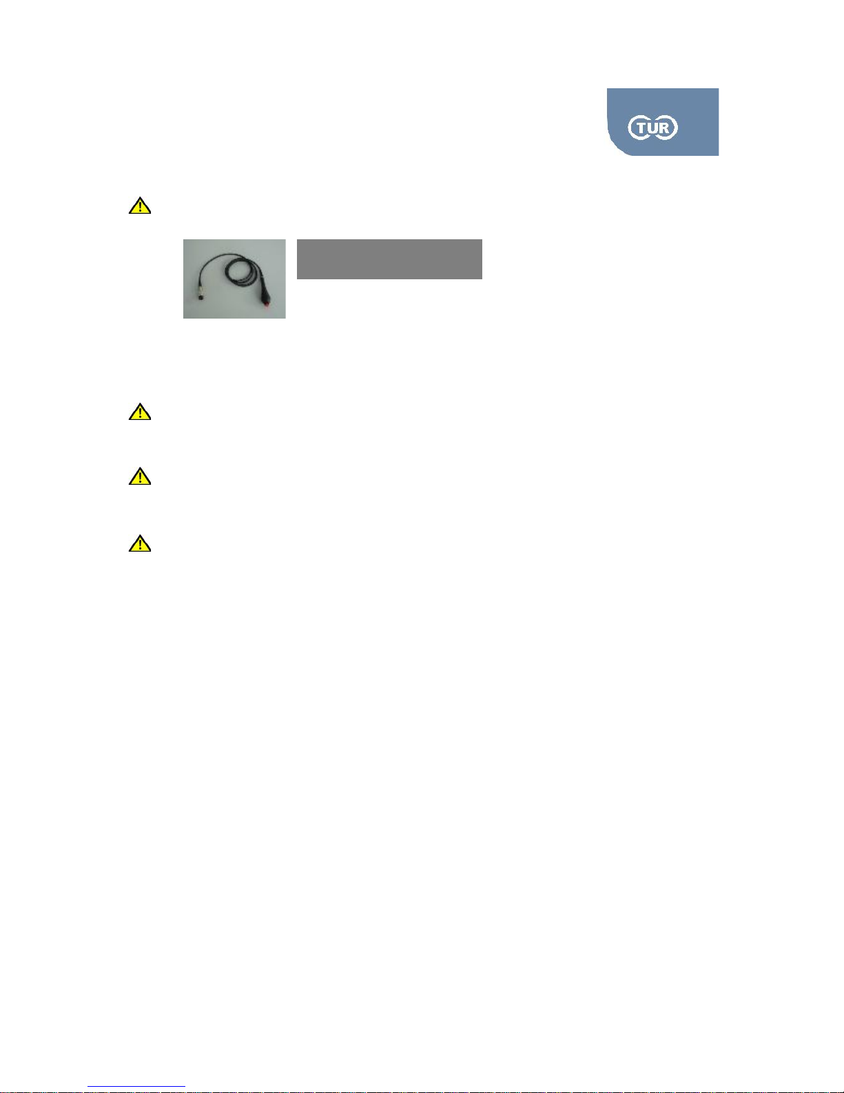
Would at any point the subject feel uncomfortable or any not normal operation would it be
observed, immediately press the emergency stop. Also, refer to 2.15.
After the activation of the emergency stop the start-up procedure of the system must be
repeated.
Immediately release the patient in case he/she feels uncomfortable by pressing the emergency
and removing the straps that keep the adapter in contact with the limb.
Use of Uninterrupted Power Supply is encouraged although not related to safety issue. It
prevents loss of data due to sudden power cut. Suggested Power of UPS 1,2kW.
Movement of the ME Equipment or its parts is possible only by the continuous activation of the
control by the operator
IEC 60417-5638
Emergency Stop Label
Page 15

5.2.1 User Manual Isoforce
REV 5 01st July 2014 page 15 von 77
TUR Therapietechnik GmbH | Grubenstr. 20 | 18055 Rostock | Germany
Chapter 2 - Mechanical Overview
Page 16
5.2.1 User Manual Isoforce
REV 5 01st July 2014 page 16 von 77
TUR Therapietechnik GmbH | Grubenstr. 20 | 18055 Rostock | Germany
2.1 Dynamometer Assembly
You can easily and comfortably make the following dynamometer’s translations.
2.1.1.Dynamometer Rotation
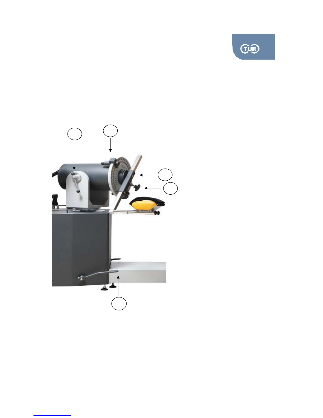
You can rotate the dynamometer in the horizontal plane, both clockwise and counter-clockwise. In order
to do so, just lightly step on the dynamometer release pedals, DR pedals. While pressing them you can
rotate the dynamometer either directions. On the rotation scale, which is placed under the
dynamometer yoke, and around the vertical tube, you can read the dynamometer’s position.
1
Dynamometer Release pedals (DR)
2
Input adaptor tube
3
Adaptors’ knob
4
Range of motion mechanical stops
5
Dynamometer Tilt Level (DT)
1
2
3
4
5
Pic 2.1 Dynamometer Assembly
Page 17
5.2.1 User Manual Isoforce
REV 5 01st July 2014 page 17 von 77
TUR Therapietechnik GmbH | Grubenstr. 20 | 18055 Rostock | Germany
2.1.2.Dynamometer Tilt
The dynamometer tilt is actually the rotation of the dynamometer in the vertical plane. To perform this
move, you should loosen the Dynamometer Tilt Lever in a counter-clockwise direction, DT Lever, and
rotate the dynamometer vertically to the desired position. While keeping it steady, use your other hand
to firmly tighten the DT knob, by turning it clockwise. If the dynamometer is not in the vertical position (0
degrees tilt), you should also support the dynamometer while loosening the DT knob. The tilt position of
the dynamometer can be read on the tilt scale.
2.1.3. Dynamometer Lifting
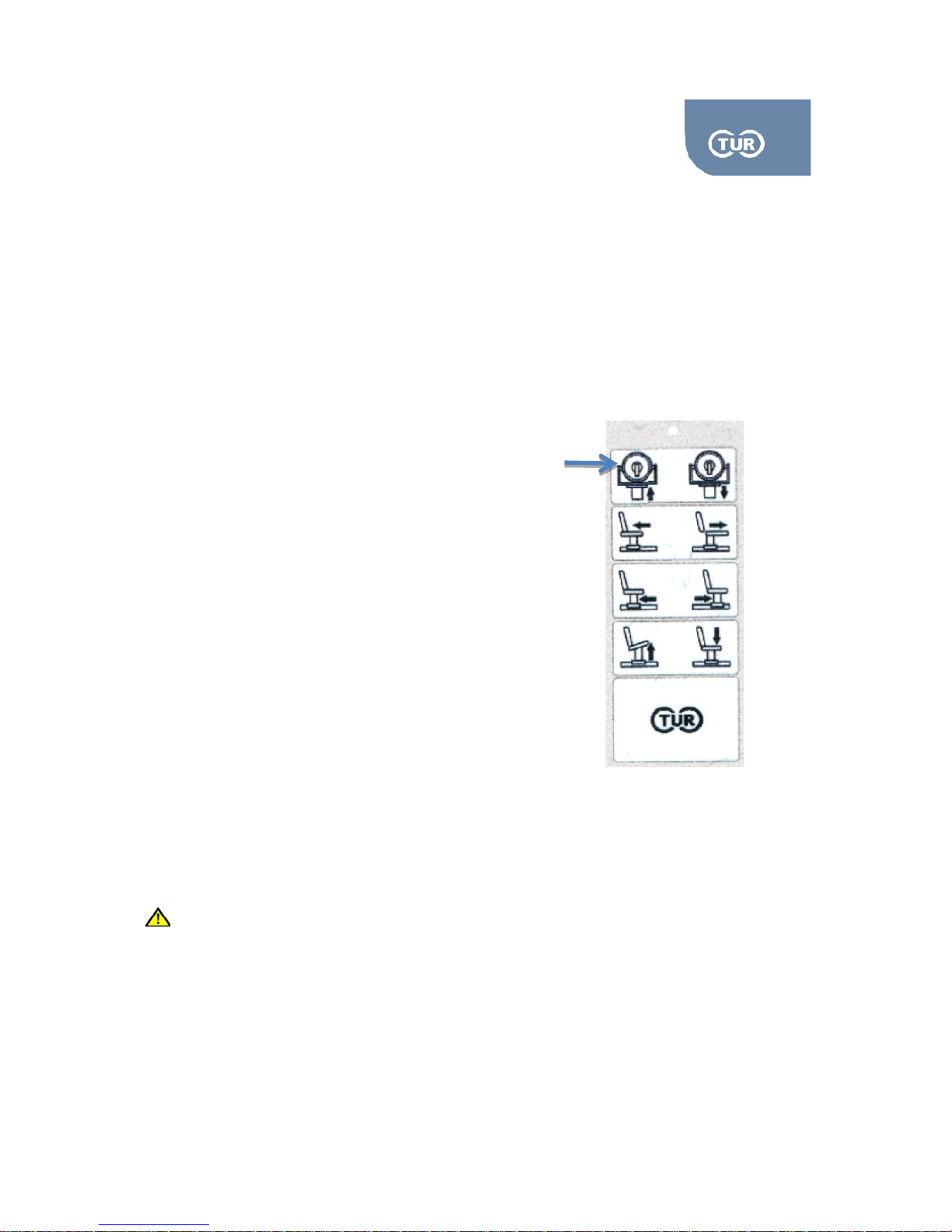
The Iso-Force system offers the easiest possible
way to lift the dynamometer. Step on the DR pedals
and press the up and down arrows that are placed on the
handheld control. When pressing the up button, the
dynamometer rises. On the contrary when pressing the down
arrow the dynamometer lowers and finally returns to its
initial position. Please note that unless you have completely
pressed the DR pedals down the motor that lifts the
dynamometer will not work.
2.1.4 Range of Motion (ROM) Ring & ROM Mechanical Stops
You can adjust the mechanical stops by pulling the knob at their back side. The stops are released and
you can move them around the dynamometer ring. Once you find the desired position gently leave the
knob.
Attention! Although the software of Isoforce applies software stops, you are asked to always place
the mechanical stops slightly beyond the software stops. This is an extra safety feature.
2.2 Dynamometer Lift Button
Page 18
5.2.1 User Manual Isoforce
REV 5 01st July 2014 page 18 von 77
TUR Therapietechnik GmbH | Grubenstr. 20 | 18055 Rostock | Germany
2.1.5 Hand-Held Emergency Button
By pressing the red emergency button the patient or the user can instantly terminate the operation of
Iso-Force, no matter in which mode the system works. The dynamometer shaft stops moving or
applying resistance. One should be particular careful when pressing the emergency button, as the
kinetic energy already acquired (particularly in isotonic and concentric isokinetic mode) by the subject
could result in continuation of the movement towards an undesired position or direction. After pressing
the emergency button, the user should manually get the patient’s limb in a safe position. Also, please
note that after terminating operator this way, the system should be reset.
2.1.6 Input Arm Adaptor
You can find the input arm adaptor at the front of the dynamometer. Attachment and adaptors are
placed in it by sliding them in. Always firmly secure the attachments by turning the knob counter
clockwise.
Hold the adaptors when you are removing them. You are advised not to have them in vertical
position as the can fall off the input.
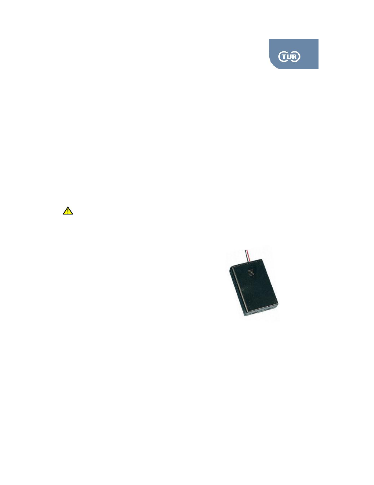
Mounted on the centre of the dynamometer rotation axis you can find the laser pointer, which is used
for easy joint alignment. The connected battery case carries a magnet and can be attached at the side
of the input adapter. To replace the batteries follow the steps below:
2.1.7 Laser Pointer
Remove the battery compartment cover and lift it off
Place 2 1,5V batteries of AAA size into the battery
compartment with the correct polarity.
Put back the battery cover.
2.3 Battery Case
Page 19
5.2.1 User Manual Isoforce
REV 5 01st July 2014 page 19 von 77
TUR Therapietechnik GmbH | Grubenstr. 20 | 18055 Rostock | Germany
2.2 Chair Assembly
2.2.1 Seat Rotation
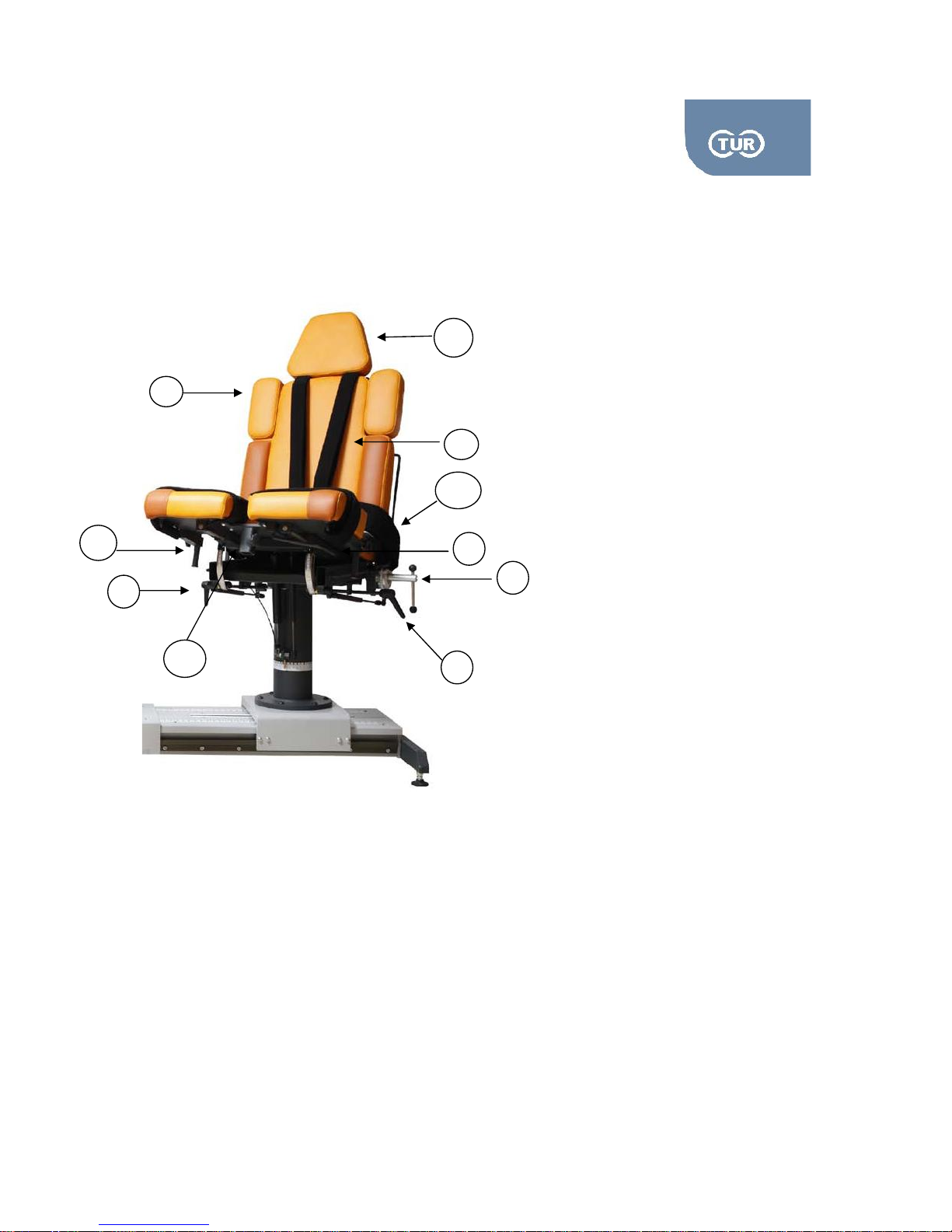
You can rotate the chair 360 degrees in the horizontal plane. To allow rotation turn the Rotation Chair
Handle (RCH) in counter clockwise direction and place the chair in the desired position. Firmly tighten
the RCH by turning it clockwise. There are two RCHs, one at each side, right under the seat. Record
the rotation position by reading the Seat Rotation Scale located around the tube of the chair.
1
Seat Back Tilt Handle (STH)
2
Rotation Chair Handle (RCH)
3
Cervical Support
4
Shoulder Support
5
Belts
6
Receiving Tube
7
Hand Grips
8
Belts
4
2
1
3
3
4
2.4 Chair Assembly
7
6
7
80
Page 20
5.2.1 User Manual Isoforce
REV 5 01st July 2014 page 20 von 77
TUR Therapietechnik GmbH | Grubenstr. 20 | 18055 Rostock | Germany
2.2.2 Chair Transfer
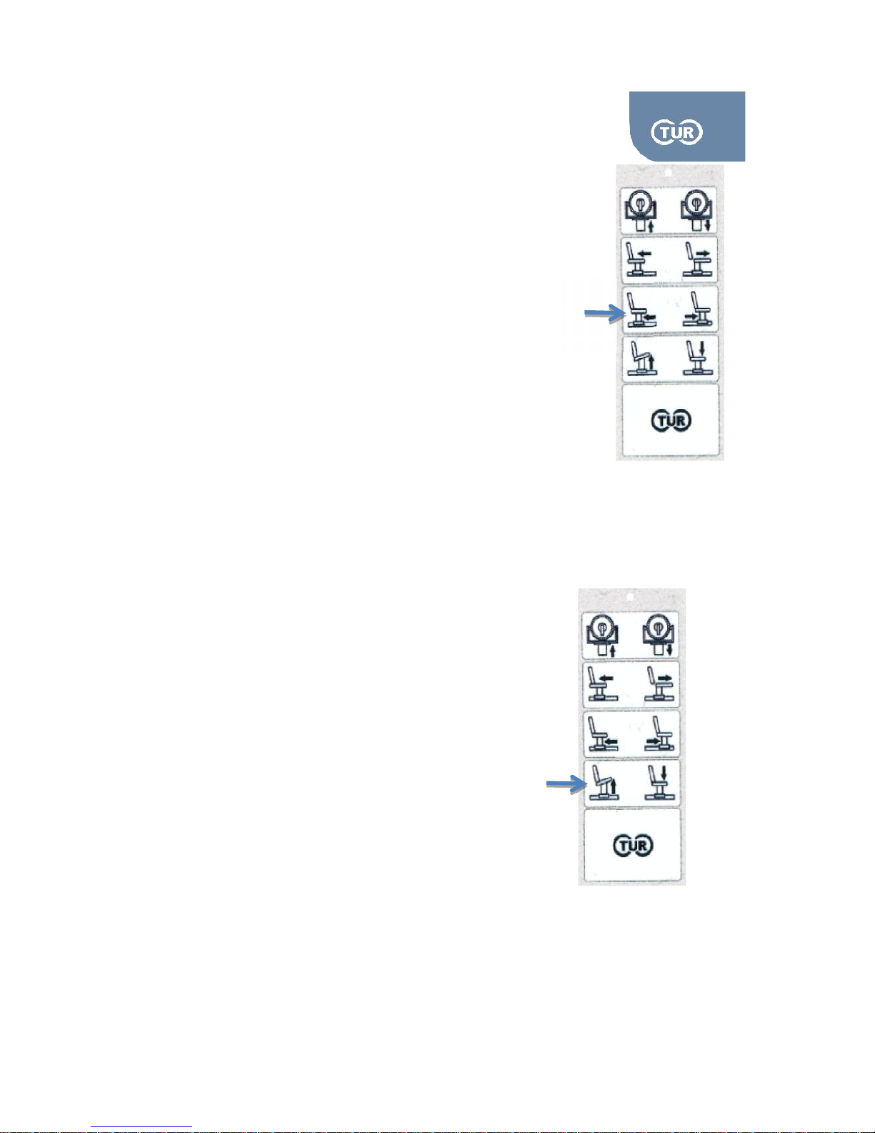
You can allow for/aft adjustment of the positioning chair
in relation to the dynamometer by pressing the left/right buttons
placed on the hand-held control panel. Iso-Force offers electric
transfer of the chair in the horizontal plane. The Chair Transfer
Scale can be found on the rail.
2.2.3 Seatback Tilt
This adjustment allows stepless change of the seat back tilt. To adjust the seat back tilt rotate the Seat
back Tilt Handle (STH) counter clockwise. Be careful as the seat back returns to the initial position
because of the supporting gas spring. Hold the back firmly by the support located at the rear side of the
back seat and adjust the tilt. Once you reach the desired position tighten firmly the STH by turning it
clockwise. Read the new position on the Seatback Tilt Scale place next to the STH.
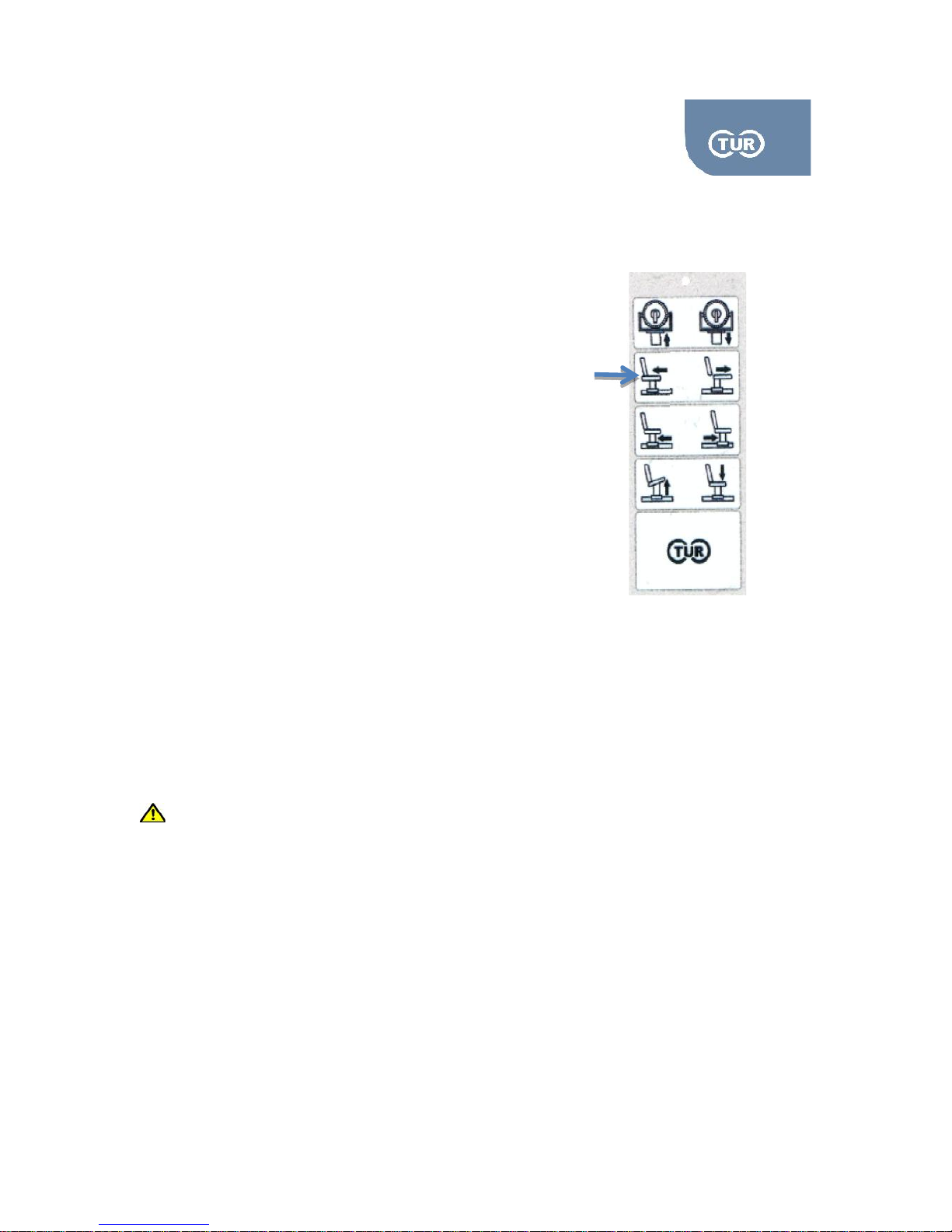
2.2.4 Bottom Seat Tilt –Height
The seat allows gas-spring assisted change
in the height of the bottom seat. The adjustment
can be set with patients placed on it. In order to
adjust the height press the button of the hand control with
the relevant button (see the picture next to the text)
2.5 Chair Transfer
2.6 Bottom Seat Tilt
Page 21
5.2.1 User Manual Isoforce
REV 5 01st July 2014 page 21 von 77
TUR Therapietechnik GmbH | Grubenstr. 20 | 18055 Rostock | Germany
2.2.5 Bottom Seat For/Aft
Press the bottom of the hand control
With the relative image.
2.2.6 Cervical Support
To reposition the cervical support turn the Cervical Support Knobs (CSK) counter clockwise. Place the
cervical support to the desired position and secure it by turning the CSKs clockwise.
2.2.7 Stabilization Straps
The system comes with the following Velcro straps and belts:
1. Pelvic Stabilization belt. In the middle of the belt, there are two metal hooks. The trunk
stabilization belts are inserted through the hooks. The two edges of the belt are inserted in the
hooks located at the side of the lower seat.
2. Thigh Stabilization straps, permanently placed on the lower seat
3. Trunk Stabilization belts, permanently placed on the back seat
To avoid skin irritation always have a piece of cloth between the Velcro stripe and the patient
tissue.
2.2.8 Hand Grips
The handle grips are covered with foam material for convenience. They can be used by the patient for
added support, stabilization and hands positioning. You can adjust the height of the handgrips by
turning the Hand Grip Knobs (HGK) counter clock wise. After adjusting the position tighten firmly by
turning the HGKs clock wise.
2.2.9 Receiving Tubes
There is one receiving tube placed in the middle of the front part of the seat. For the adapters placed in
this tube please refer to chapter 3. There is a tightening knob permanently placed on the tube. To place
2.7 Bottom Seat For-afth
Page 22

5.2.1 User Manual Isoforce
REV 5 01st July 2014 page 22 von 77
TUR Therapietechnik GmbH | Grubenstr. 20 | 18055 Rostock | Germany
one of the adapters in the receiving tube, turn the knob counter clockwise, put the adapter in, and
secure it, by turning the knob clockwise.
Page 23
5.2.1 User Manual Isoforce
REV 5 01st July 2014 page 23 von 77
TUR Therapietechnik GmbH | Grubenstr. 20 | 18055 Rostock | Germany
2.3 Adapters
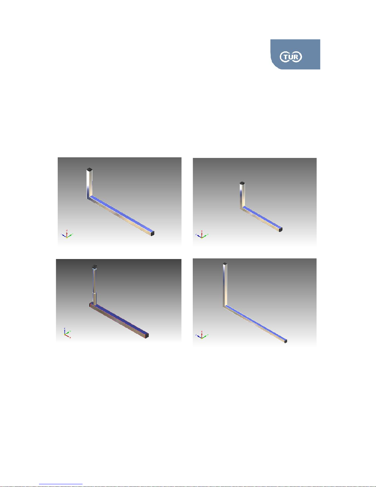
2.3.1 Dynamometer and Chair Attachments/Adapters
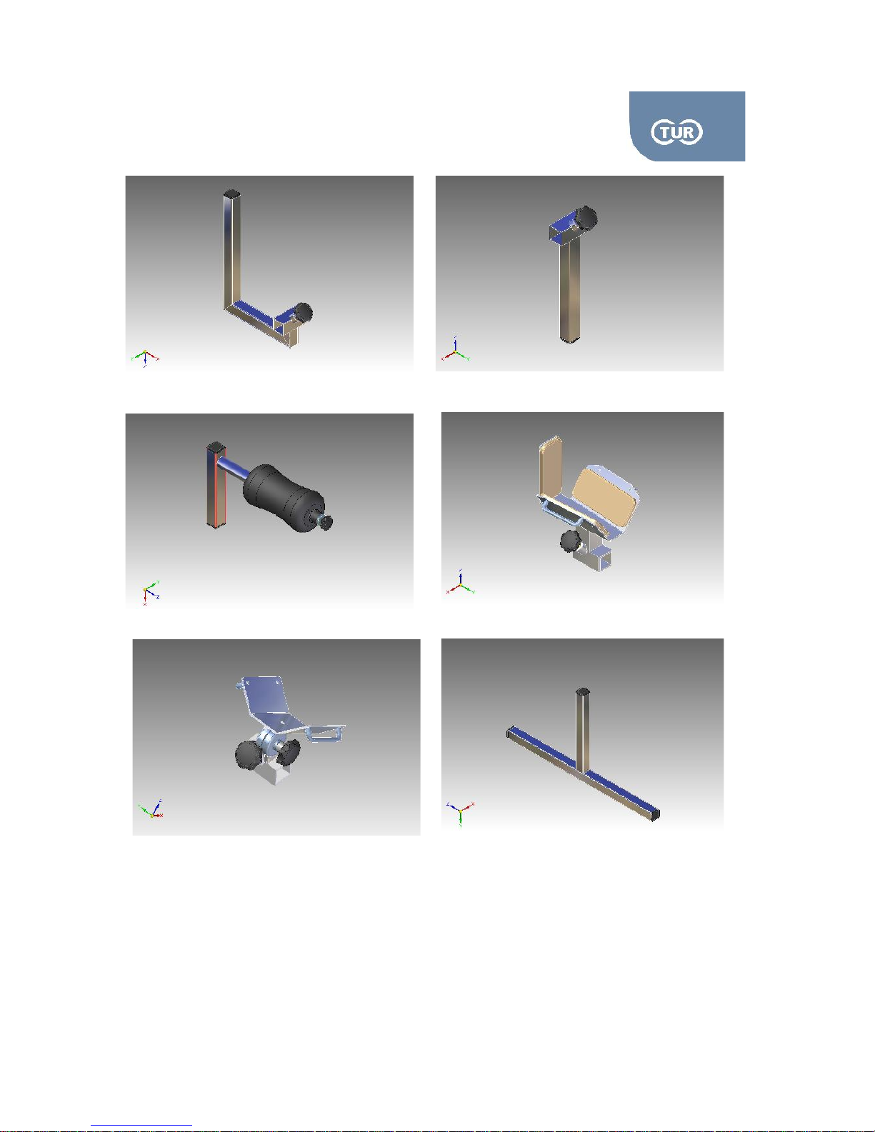
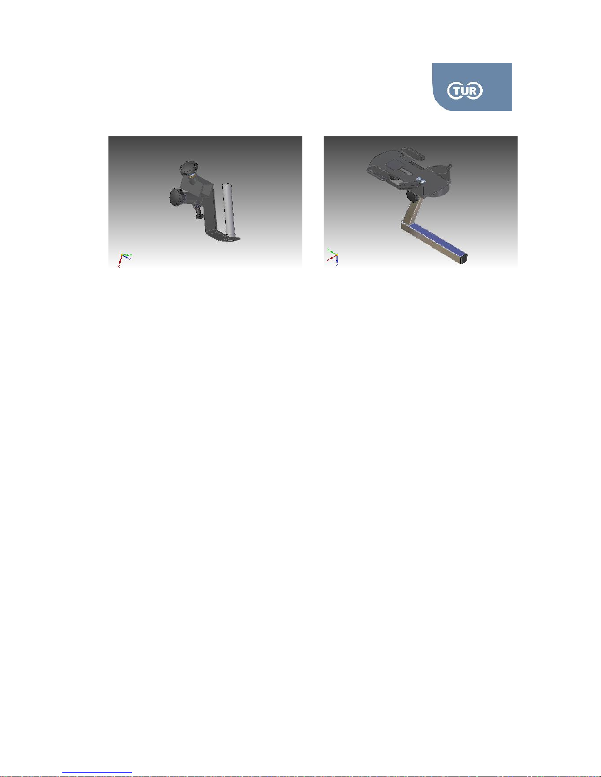
Iso-Force comes with a set of 16 adapters as standard. These can be used either alone or combined.
Below you can see a list of the available standard adaptors, along with the possible combinations and
their use.
Pic. 2.08, ADL1 Angle Attachment
Pic. 2.10, ADL3 Angle Attachment
Pic. 2.09, ADL2 Angle Attachment
Pic. 2.11, ADL4 Angle Attachment
Page 24
5.2.1 User Manual Isoforce
REV 5 01st July 2014 page 24 von 77
TUR Therapietechnik GmbH | Grubenstr. 20 | 18055 Rostock | Germany
Pic. 2.12, ADL5
Pic. 2.13, ADS1
Pic. 2.14, ADS2
Pic. 2.15, ADS3
Pic. 2.17, ADT1
Pic. 2.16, ADS4
Page 25
5.2.1 User Manual Isoforce
REV 5 01st July 2014 page 25 von 77
TUR Therapietechnik GmbH | Grubenstr. 20 | 18055 Rostock | Germany
ADL1 – Angle attachment, dimensions 255x655mm – Used for elbow flex-ext & shoulder int/ext rotation
ADL2 –Angle attachment, dimensions 355x655mm – Used as Thigh stabilizer tube
ADL3 – Angle attachment used either with knee pad or with antishear knee adapter
ADL4 – Angle attachment, dimensions 555x1155mm – Elbow/Shoulder Adaptor
ADL4 – Angle attachment used for ankle patterns
ADLS1 – Stabilizer used with ADLS2 for contralater knee stabilization or with ADT1 for footrest
ADLS2 – Contralateral knee pad
ADS3 – Elbow Stabilizer
ADS4 – Thigh & Forearm Stabilizer Pad
ADT1 – T-shape adapter used with ADLS1 for footrest
AD0W1 – Wrist Adapter
ADA1 – Ankle adapter
Pic. 2.18, ADW1
Pic. 2.19, ADA1
Page 26

5.2.1 User Manual Isoforce
REV 5 01st July 2014 page 26 von 77
TUR Therapietechnik GmbH | Grubenstr. 20 | 18055 Rostock | Germany
Chapter 3 - Set Up / Positioning / Operation
Page 27
5.2.1 User Manual Isoforce
REV 5 01st July 2014 page 27 von 77
TUR Therapietechnik GmbH | Grubenstr. 20 | 18055 Rostock | Germany
3.0 Set Up and Positioning
In the following chapters details instructions for set up and positioning of the Iso-Force system for the
standard test and exercises. For every joint pattern there is a quick reference guide to help you make
the gross positioning. However, depending on the anatomical features of your subject further set ups
will be needed in order to ensure proper alignment and comfortable position.
You are strongly advised to perform several trials with healthy subjects in order to get familiar with the
positioning required for each joint pattern.
In the Iso-Force software you can find additional photos for each position that can help you and guide
you during an actual testing.
Start Up
Press the ON/OFF button at the front panel of your computer. Wait a few minutes to ensure that the
Windows are fully loaded.
Double click on the isoforce shortcut at the desktop.
The isoforce main menu appears in your screen.
Shut Down
Exit the software by right clicking on the exit button at the main menu.
To shut down your computer:
1. Select Start at the lower left side of your desktop
2. Select Turn off Computer from the appearing start menu
3. Select Shut Down to terminate operation
Page 28
5.2.1 User Manual Isoforce
REV 5 01st July 2014 page 28 von 77
TUR Therapietechnik GmbH | Grubenstr. 20 | 18055 Rostock | Germany
3.1 Ankle
The ankle is a complex joint. What we normally think of as the ankle
is actually made up of two joints: the subtalar joint, and the true ankle joint. The true ankle joint is
composed of 3 bones, seen above from a front, or anterior, view: the tibia which forms the inside, or
medial, portion of the ankle; the fibula which forms the lateral or outside portion of the ankle; and the
talus underneath. The true ankle joint is responsible for up and down motion of the foot.
Beneath the true ankle joint is the second part of the ankle, the subtalar joint, which consists of the talus
on top and calcaneus on the bottom. The subtalar joint allows side to side motion of the foot.
The ends of the bones in these joints are covered by articular cartilage. The major ligaments of the
ankle are: the anterior tibiofibular ligament, which connects the tibia to the fibula; the lateral collateral
ligaments, which attach the fibula to the calcaneus and gives the ankle lateral stability; and, on the
medial side of the ankle, the deltoid ligaments, which connect the tibia to the talus and calcaneus and
provide medial stability.
These components of your ankle, along with the muscles and tendons of your lower leg, work together
to handle the stress your ankle receives as you walk, run and jump.
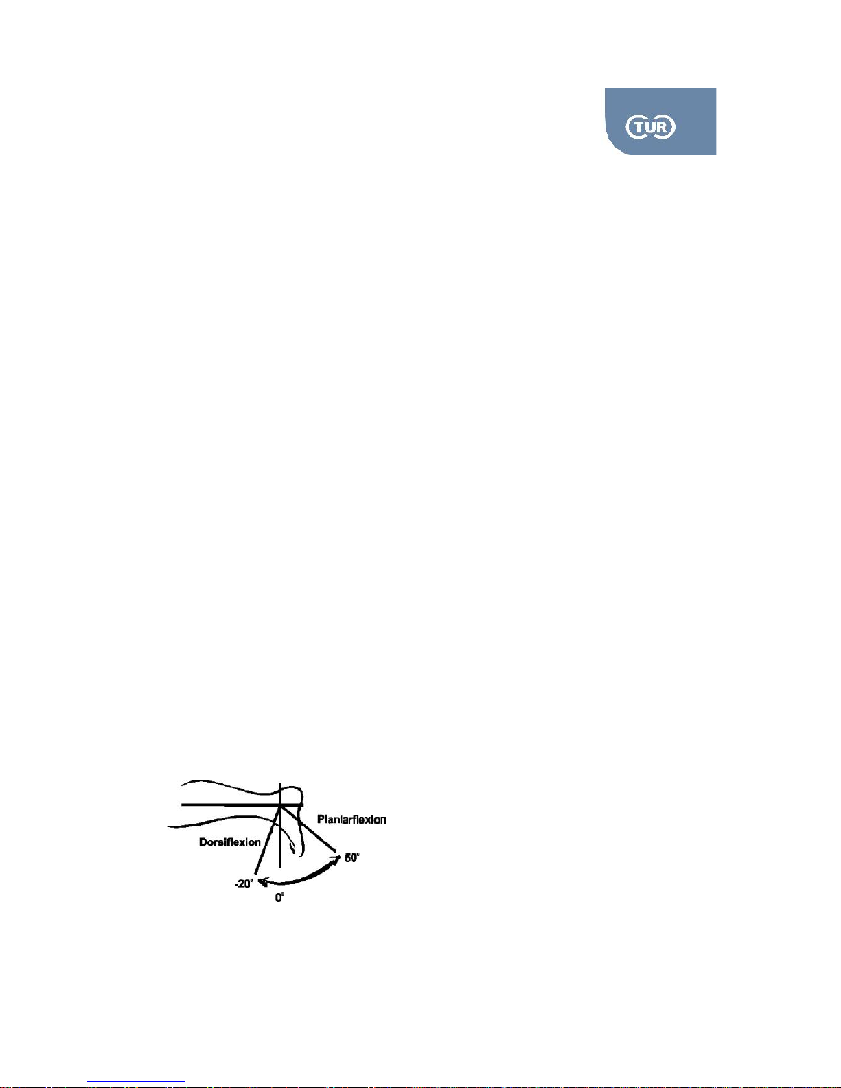
3.1.1 PlantarFlexion/DorsiFlexion
Rotation Axis: It passes through the malleoli.
Anatomical Zero: In neutral position. To be sure that you set it correctly ask your subject to stand
without wearing shoes and make a measurement with goniometer defining the angle the tibia forms to
the foot taking the malleoli as the center of the angle. Reproduce the angle after the subject is
positioned and stabilizes on isoforce.
Range of Motion: 25 degrees for dorsiflexion, 50 degrees for plantarflexion,
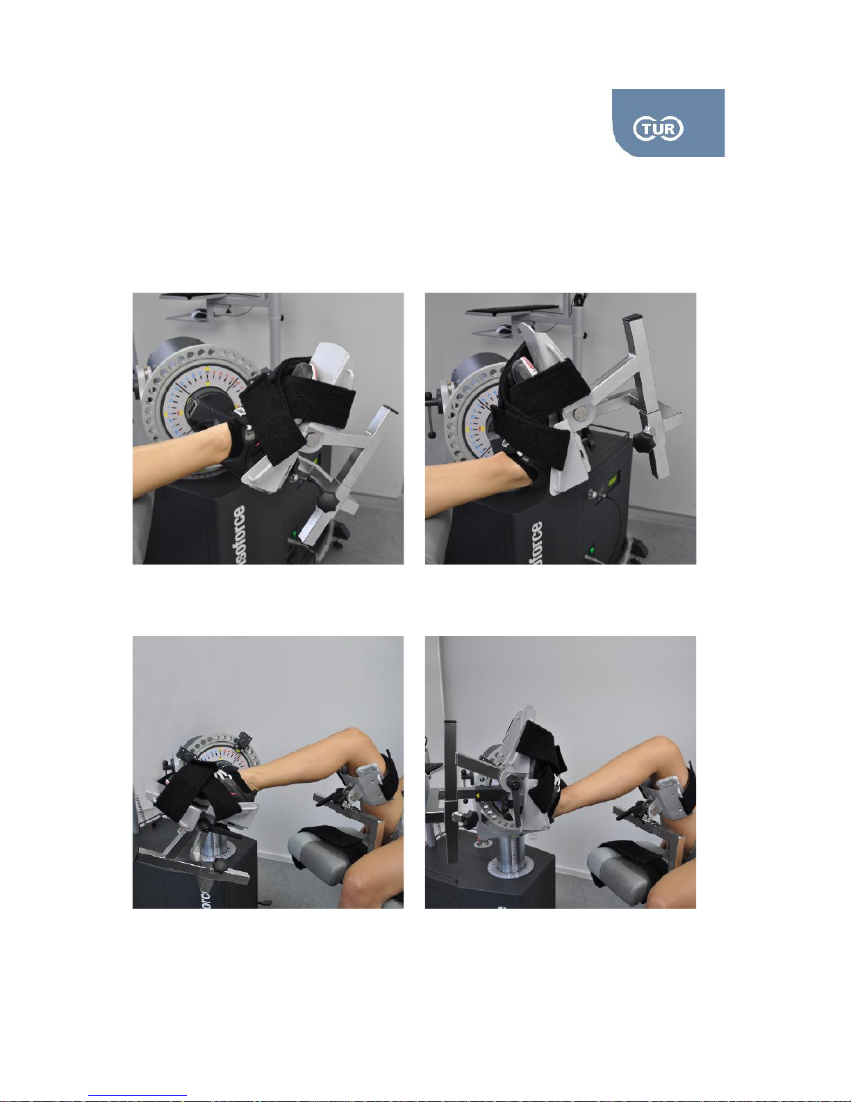
Isoforce offers two positioning possibilities, one in prone position, that can also be modified to seated
and one in supine.
Page 29
5.2.1 User Manual Isoforce
REV 5 01st July 2014 page 29 von 77
TUR Therapietechnik GmbH | Grubenstr. 20 | 18055 Rostock | Germany
Supine Position
Muscles Involved: Tibialis anterior/posterior, toe extensors/flexors, peroneus tertius, triceps surae,
peroneus longus
Modified Seated
Page 30

5.2.1 User Manual Isoforce
REV 5 01st July 2014 page 30 von 77
TUR Therapietechnik GmbH | Grubenstr. 20 | 18055 Rostock | Germany
Attachments Needed
Dynamometer: Ankle attachment (ADA1), Angle attachment (ADL5)
Seat: Angle Attachment (ADS1), Thigh Pad (ADS4) / For modified seated only
Set up & positioning
Put the mechanical stops to “B” red and “B” red.
Combine the ankle (ADA1) and the angle attachment ADL5. Attach it to the dynamometer by
sliding it in the input arm from the top, short side. Tighten it firmly by turning the knob placed in the
input arm clock wise.
For the seated position combine the ADS1 with the ADS4 and place it in the receiving tube of the
seat by sliding it from the top. Tighten it firmly by turning the knob placed in the input arm clock
wise. The attachment should be facing the leg to be tested. Set it low as it is much easier to adjust
it higher if needed. Insert the thigh pad stabilizer in the vertical angle with its vertical section
towards the inside. Secure firmly.
Ask the subject to lay on the chair facing the dynamometer.
Place the subject's ankle in the ankle adapter and secure it firmly by tightening the straps.
The stabilizer of the thigh should be just above the posterior joint line, while it is also maintained in
a straight line between the hip and the ankle. Secure it with the strap. Do not over tighten it.
Set the axis of the joint rotation. The axis of rotation goes from the machine and extends through
the lateral condyle. To check the alignment simply plantar and dorsiflex the ankle and ensure the
heel does not lift from the footplate
If the subject feels it more comfortable or/and if you want the subject to view the monitor, lift the
chair back and modify the supine position to seated.
Opposite Side
Unstrap patient's thigh from the stabilizer, as well as his/her ankle.
Slide the chair away from the dynamometer.
Remove the seat attachments and place them the other way around, the angle should face the
other side.
Adjust the chair and the dynamometer in accordance to the quick reference above.
Follow the steps 6 -9 as described above.
Page 31
5.2.1 User Manual Isoforce
REV 5 01st July 2014 page 31 von 77
TUR Therapietechnik GmbH | Grubenstr. 20 | 18055 Rostock | Germany
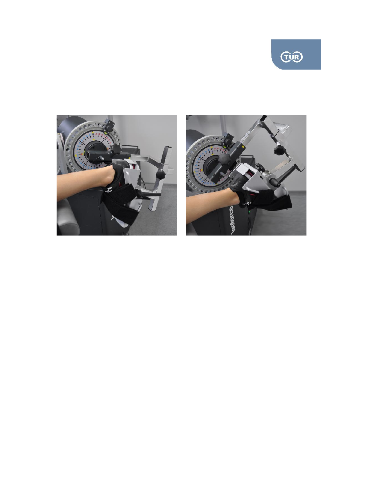
In Prone Position
Muscles Involved: Tibialis anterior/posterior, toe extensors/flexors, peroneus tertius, triceps surae,
peroneus longus
Attachments Needed
Dynamometer: Ankle attachment (ADA1), Angle attachment (ADL5)
Set up & positioning
Put the mechanical stops to “B” red and “B” red.
Combine the ankle (ADA1) and the angle attachment ADL5. Attach it to the dynamometer by
sliding it in the input arm from the top, short side. Tighten it firmly by turning the knob placed in the
input arm clock wise.
Adjust the chair and the dynamometer in accordance to the quick reference above.
Ask the subject to lay on the chair in a prone position.
Place the subject's ankle in the ankle adapter and secure it firmly by tightening the straps.
Set the axis of the joint rotation. The axis of rotation goes from the machine and extends through
the lateral condyle. To check the alignment simply plantar and dorsiflex the ankle and ensure the
heel does not lift from the footplate.
Page 32
5.2.1 User Manual Isoforce
REV 5 01st July 2014 page 32 von 77
TUR Therapietechnik GmbH | Grubenstr. 20 | 18055 Rostock | Germany
Opposite Side
Unstrap patient's thigh from the stabilizer, as well as his/her ankle.
Slide the chair away from the dynamometer.
Remove the seat attachments and place them the other way around, the angle should face the
other side.
Adjust the chair and the dynamometer.
Follow the steps 6 -9 as described above.
Considerations
Normal Range of Motion for dorsiflexion is considered to be 25°, while for plantarflexion up to 50°.
The angle of peak torque has been found to be around 25° of plantarflexion.
When the exercise is performed in prone sure, ensure full support of the knee. Otherwise pain can
occur due to hyperextension.
The angular velocity of choice is 30°/sec.
Gait cycle simulation is possible and particularly useful for neurological rehabilitation.
Design a program that comprises of the following sequence:
Eccentric dorsiflexion (heelstrike) and eccentric plantarflexion (midstance)
Concentric dorsiflexion (toe off) and concentric plantarflexion (swing phase)
Attention! The ankle is known to be unstable in a plantarflexed position. Please keep that in mind when
testing or exercising a subject.
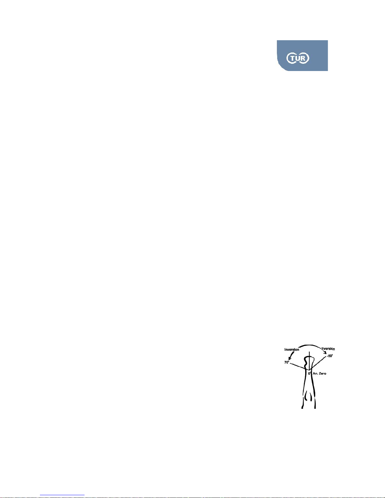
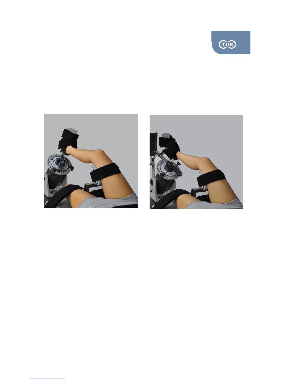
3.1.2 Inversion/Eversion
Rotation Axis: The rotation axis of the dynamometer extends through the center of
the calcaneus
Anatomical Zero: In neutral position. To be sure that you set it correctly ask your
subject to stand without wearing shoes and make a measurement with goniometer
defining the angle the tibia forms to the foot taking the malleoli as the center of the
angle. Reproduce the angle after the subject is positioned and stabilizes on isoforce.
A tip is that in neutral position at this pattern the foot should point to the roof.
Range of Motion: Up to 40 degrees for inversion and up to 25 degrees for eversion,
Page 33
5.2.1 User Manual Isoforce
REV 5 01st July 2014 page 33 von 77
TUR Therapietechnik GmbH | Grubenstr. 20 | 18055 Rostock | Germany
Isoforce offers two positioning possibilities, one in prone position that can also be
modified to seated and one in supine.
Muscles Involved: Tibialis pesterior/anterior, extensor hallucis longus, flexor hallucis longus, flexor
digitorum longus, extensor digitorum longus, peroneus tertius, peroneus brevis and peroneus longus.
Seated Position
Attachments Needed
Dynamometer: Ankle attachment (ADA1),
Seat: Angle Attachment (ADS1), Thigh Pad (ADS4) / For modified seated only
Set up & positioning
Put the mechanical stops to “B” red and “B” red.
Attach the ankle (ADA1) to the dynamometer by sliding it in the input arm from the top, short side.
Tighten it firmly by turning the knob placed in the input arm clock wise.
For the seated position combine the ADS1 with the ADS4 and place it in the receiving tube of the
seat by sliding it from the top. Tighten it firmly by turning the knob placed in the input arm clock
wise. The attachment should be facing the leg to be tested. Set it low as it is much easier to adjust
it higher if needed. Insert the thigh pad stabilizer in the vertical angle with its vertical section
towards the inside. Secure firmly.
Ask the subject to lay on the chair facing the dynamometer.
Page 34

5.2.1 User Manual Isoforce
REV 5 01st July 2014 page 34 von 77
TUR Therapietechnik GmbH | Grubenstr. 20 | 18055 Rostock | Germany
Place the subject's ankle in the ankle adapter and secure it firmly by tightening the straps.
The stabilizer of the thigh should be just above the posterior joint line. Secure it with the strap. Do
not overtighten it. Tip! Set the dynamometer in approximately 55 degrees tilt before you position
the subject and position the ADS4 in a way that the subject can put the ankle on the foot plate.
Set the axis of the joint rotation. The axis of rotation goes from the machine and extends through
the centre of calcaneus.
Opposite Side
Unstrap patient's thigh from the stabilizer, as well as his/her ankle.
Slide the chair away from the dynamometer.
Remove the seat attachments and place them the other way around, the angle should face the
other side.
Adjust the chair and the dynamometer.
Follow the steps 6 -9 as described above.
Page 35
5.2.1 User Manual Isoforce
REV 5 01st July 2014 page 35 von 77
TUR Therapietechnik GmbH | Grubenstr. 20 | 18055 Rostock | Germany
3.2 Hip
The hip joint is a ball and socket joint, formed by the head of the Femur (thigh bone) and the
acetabulum of the pelvis. The dome-shaped head of the femur forms the ball, which fits snuggly into the
concave socket of the acetabulum. The hip joint is a very sturdy joint, due to the tight fitting of the bones
and the strong surrounding ligaments and muscles.
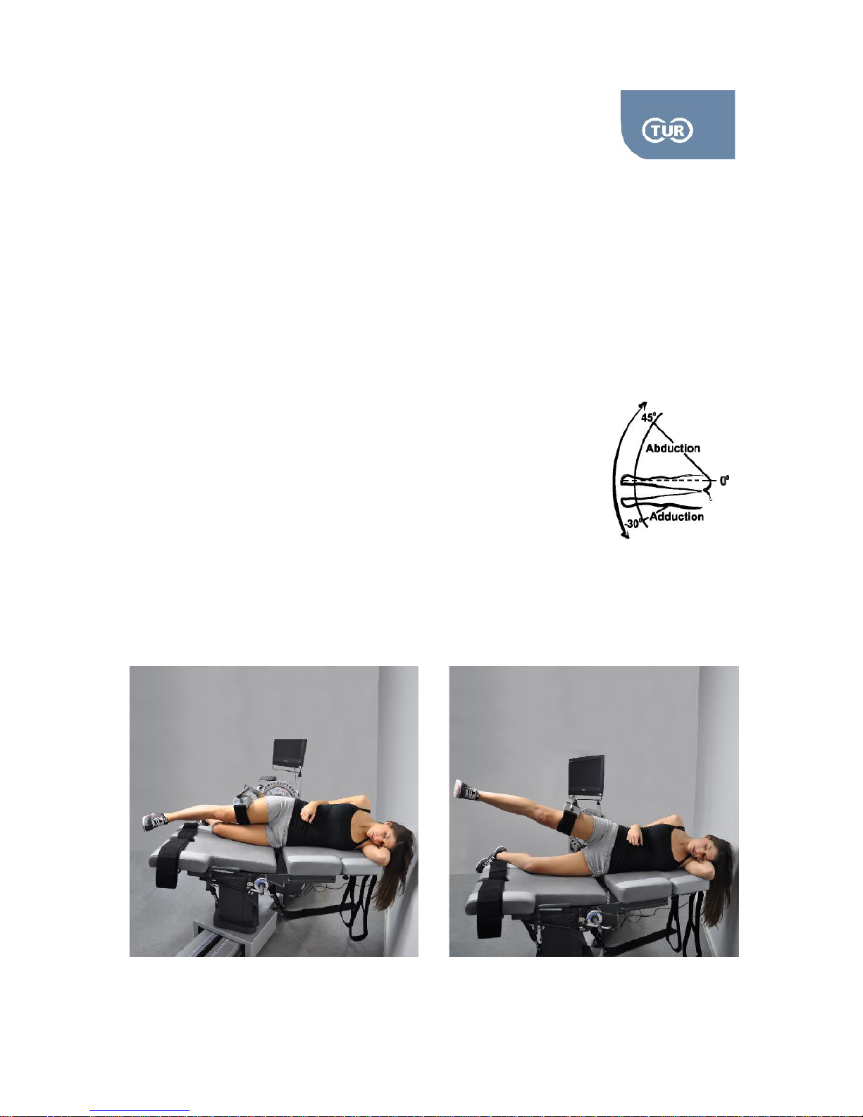
3.2.1 Hip Abduction – Adduction (Lying on Side)
Rotation Axis: Opposite the hip joint 1 cm medially to the anterior superior iliac spine
Anatomical Zero: Straight leg
Range of Motion: Up to 45 degrees for adduction and up to 25 degrees for
Abduction. However, in isokinetic position the abduction is blocked by the
other leg
Isoforce offers one positioning possibility, lazing on side. There are two variations
depending if the tester wished the subject to look or not at the screen (designated as away in the
software).
Muscles Involved: Gluteus medius, adductor magnus.
Page 36

5.2.1 User Manual Isoforce
REV 5 01st July 2014 page 36 von 77
TUR Therapietechnik GmbH | Grubenstr. 20 | 18055 Rostock | Germany
Attachments Needed
Dynamometer: Knee Adaptor (ADL3) with single knee pad
Set up & positioning
Put the mechanical stops to “C” red and “M” red.
Combine the ADL3 with the single knee pad
Attach the adapter to the dynamometer by sliding it in the input arm from the top, short side.
Tighten it firmly by turning the knob placed in the input arm clock wise.
Ask the subject to be laid on the seat facing the dynamometer, with hip to be tested on top. The
opposite limb can be slightly flexed.
Set the axis of the joint rotation. The axis is through the greater trochanter. To succeed the
alignment you might need to make alterations to the positions of the chair and the dynamometer.
The length of the attachment should be adjusted so that the pad is placed superior to the popliteal
fossa. Secure the pad by tightening the strap.
Check the axis of rotation by asking your subject to perform trial abduction and adduction.
Opposite Side
Unstrap patient's thigh from attachment.
Slide the chair away from the dynamometer.
Instruct your patient to lay around so that the hip to be tested in on top.
Follow the steps 6 -8 as described above.
Attention! Instruct your patient to hold the emergency stop during the test or the exercise, in order to
instantaneously terminate the operation in any mode in case he/she feels pain or disturbance.
Considerations
Continuous passive motion can be used for restoring ROM and preventing capsular tightening in
elderly people, especially on those with a lifestyle that does not include a lot of motion.
Page 37
5.2.1 User Manual Isoforce
REV 5 01st July 2014 page 37 von 77
TUR Therapietechnik GmbH | Grubenstr. 20 | 18055 Rostock | Germany
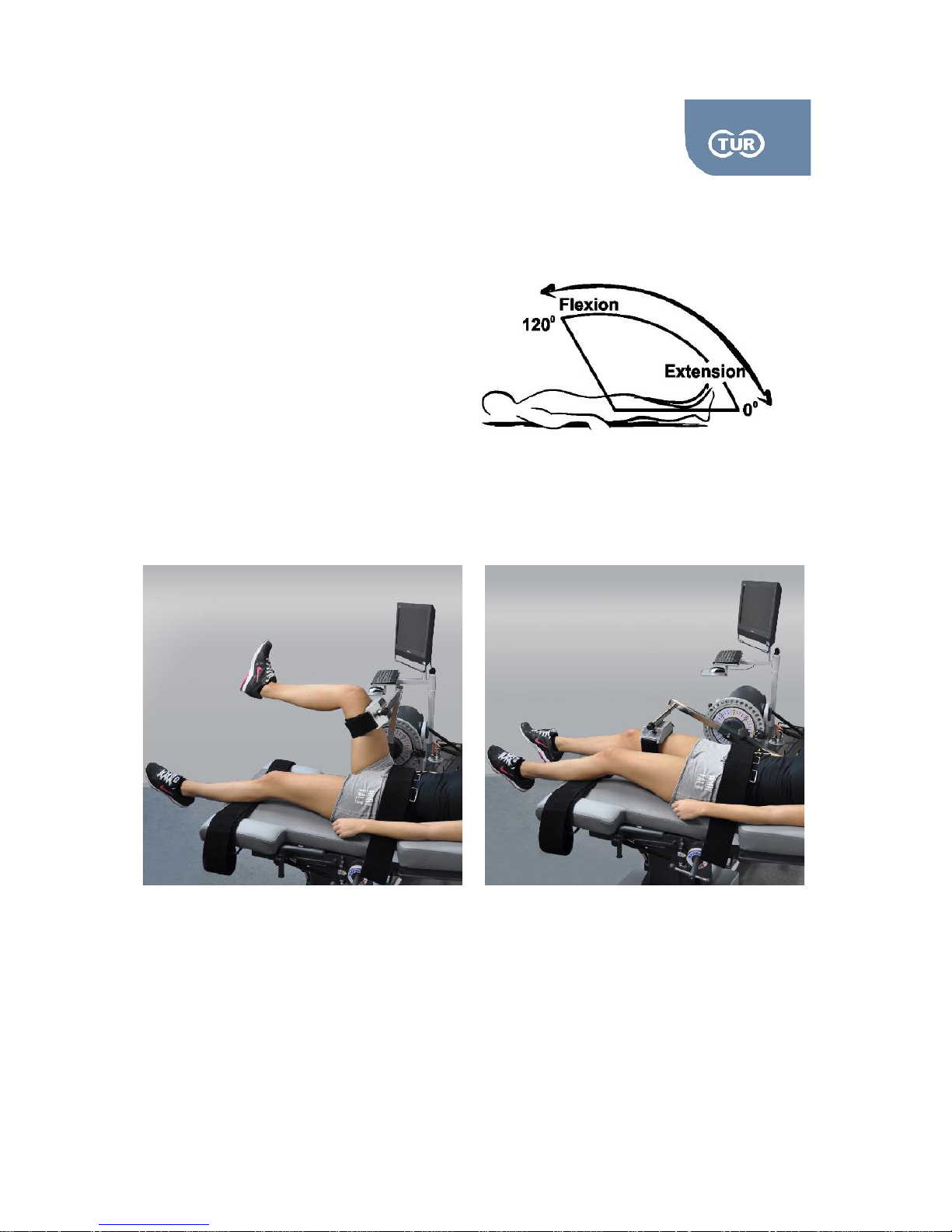
3.2.2 Hip Extension – Flexion (Supine)
Rotation Axis: Across from the greater trochanter to the axis of the dynamometer
Anatomical Zero: Straight leg
Range of Motion: Extension is blocked due to
the pattern position, flexion
ROM is up to 120 degrees
Isoforce offers one positioning possibility,
in prone position.
Muscles Involved: Rectus femoris, psoas major, glutei major and hamstrings
Attachments Needed
Dynamometer: Knee Adaptor (ADL3) with single knee pad
Page 38

5.2.1 User Manual Isoforce
REV 5 01st July 2014 page 38 von 77
TUR Therapietechnik GmbH | Grubenstr. 20 | 18055 Rostock | Germany
Set up & positioning
Put the mechanical stops to “C” red and “M” red.
Combine the ADL3 with the single knee pad.
Attach the adapter to the dynamometer by sliding it in the input arm from the top. Tighten it firmly
by turning the knob placed in the input arm clock wise.
Ask the subject to lie supine on the chair.
Set the axis of the joint rotation. The axis is through the greater trochanter. To succeed the
alignment you might need to make alterations to the positions of the chair and the dynamometer.
The length of the attachment should be adjusted so that the pad is placed anteriorly on the thigh.
Secure the pad by tightening the strap.
Check the axis of rotation by asking your subject to perform flexion of the hip.
Opposite Side
Unstrap patient's thigh from attachment.
Slide the chair away from the dynamometer.
Adjust the chair and the dynamometer to achieve alignment.
Follow the steps 5 -7 as described above.
Attention! Instruct your patient to hold the emergency stop during the test or the exercise, in order to
instantaneously terminate the operation in any mode in case he/she feels pain or disturbance.
Considerations
To gain a true picture of hip flexion range of motion, movement between the pelvis and femur in the hip
joint, the opposite thigh should be extended to minimize motion between the pelvis and spine. Please
note that extension is not possible when the pattern is executed in lying position. In order to perform
extension, the pattern should be executed standing.
Page 39
5.2.1 User Manual Isoforce
REV 5 01st July 2014 page 39 von 77
TUR Therapietechnik GmbH | Grubenstr. 20 | 18055 Rostock | Germany
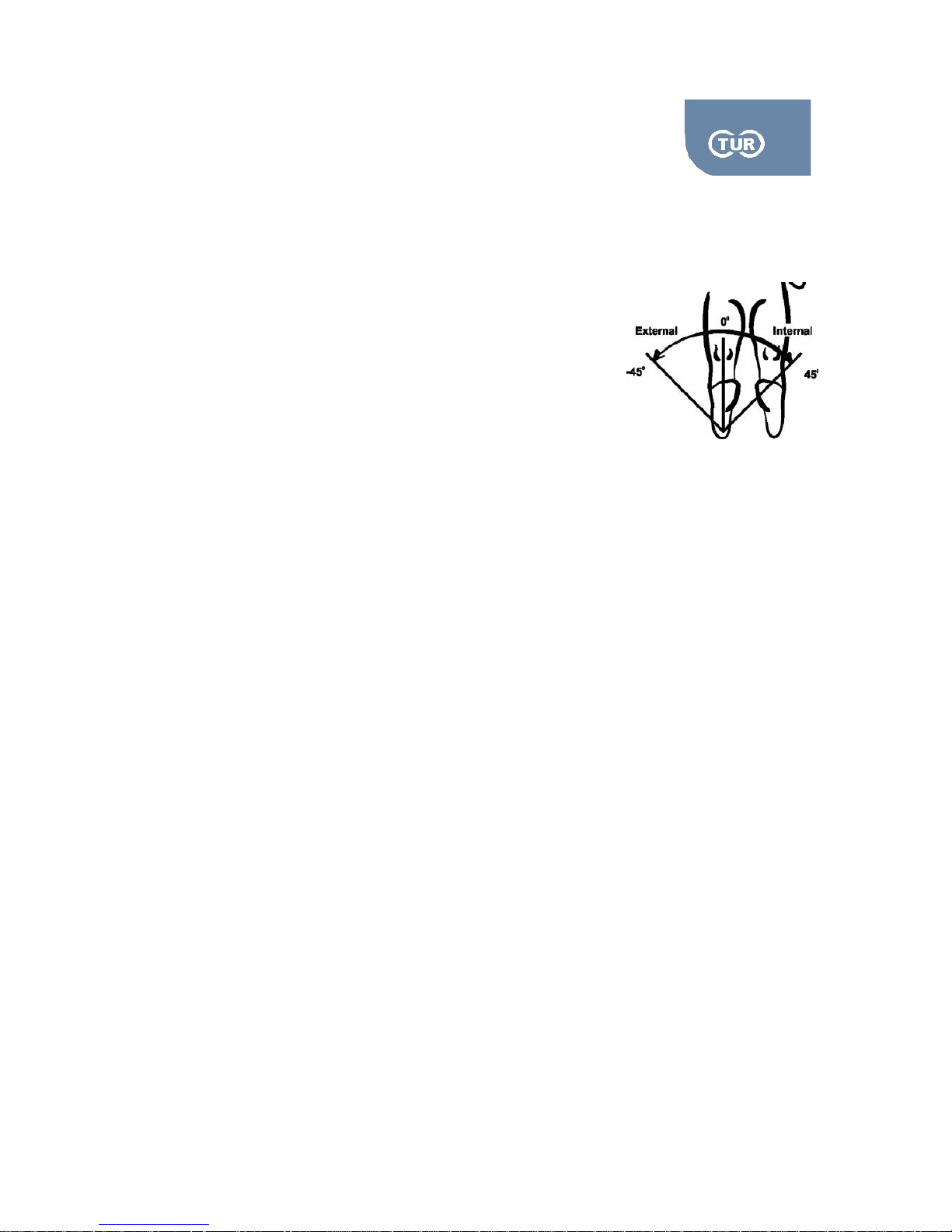
3.2.3 Hip Internal – External Rotation
Rotation Axis: Along the long axis of the femur
Anatomical Zero: Straight leg in neutral position
Range of Motion: Physiological ROM is 45 degrees in internal and
45 degrees in external rotation. However, in isokinetic testing up to
10 degrees in internal and up to 25 degrees in external rotation is suggested.
Isoforce offers one positioning possibility, in supine position.
Muscles Involved: Obturators and Gluteals
Attachments Needed
Dynamometer: Ankle Adapter (ADA1) for supine
Set up & positioning
Put the mechanical stops to “B” red and “B” red.
Attach the ankle adapter ADA1 to the dynamometer by sliding it in the input arm from the top,
short side. Tighten it firmly by turning the knob placed in the input arm clock wise..
Ask the subject to lay on the chair in supine position.
Place the subject's ankle in the ankle adapter and secure it firmly by tightening the straps.
Set the axis of the joint rotation. The axis of rotation is along the axis of the femur. Make sure that
the leg is straight and there is no flexion on the knee joint.
Opposite Side
Unstrap patient's thigh from the stabilizer, as well as his/her ankle.
Slide the chair away from the dynamometer.
Adjust the chair and the dynamometer to align the other leg. Normally only a short rotation of the
dynamometer and the chair is requires.
Follow the steps 4 -5 as described above.
Page 40
5.2.1 User Manual Isoforce
REV 5 01st July 2014 page 40 von 77
TUR Therapietechnik GmbH | Grubenstr. 20 | 18055 Rostock | Germany
3.3 Knee Joint
Although the knee joint may look like a simple joint, it is one of the most complexes. It consists of 4
bones and an extensive network of ligaments and muscles. Moreover, the knee is more likely to be
injured than is any other joint in the body.
3.3.1 Knee Extension – Flexion
Rotation Axis: Along the long axis of the femur
Anatomical Zero: Straight leg in neutral position
Range of Motion: Physiological ROM is 45 degrees in internal and
45 degrees in external rotation. However, in isokinetic testing up to
10 degrees in internal and up to 25 degrees in external rotation is suggested.
Isoforce offers one positioning possibility, in supine position.
Muscles Involved: Obturators and Gluteals
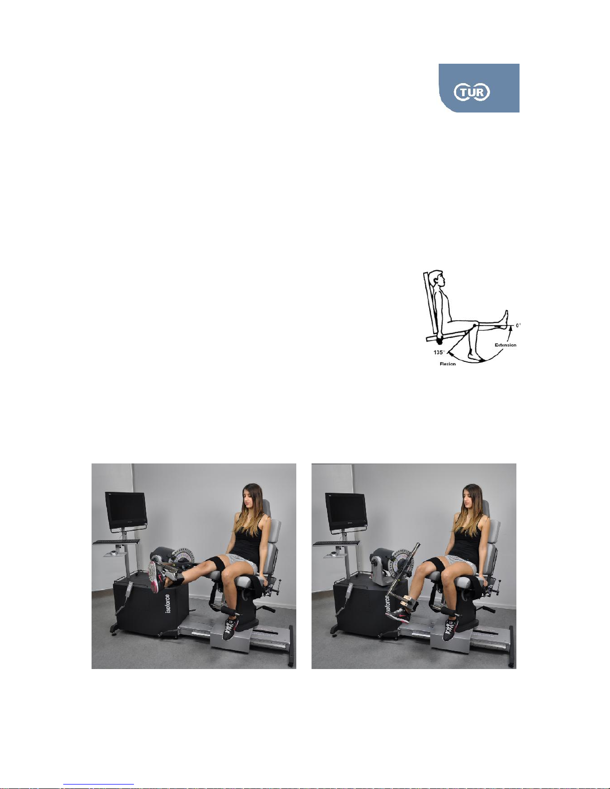
Seated
Page 41

5.2.1 User Manual Isoforce
REV 5 01st July 2014 page 41 von 77
TUR Therapietechnik GmbH | Grubenstr. 20 | 18055 Rostock | Germany
Muscles Involved: Hamstrings, Quadriceps
Attachments Needed
Dynamometer: Knee Adaptor (ADL3) with single or double knee pad
Chair: I-shape Adapter (ADS1), Contra lateral Knee Adapter (AdS2)
Set up & Positioning
Put the mechanical stops to “B” blue and “B” red.
Collect the attachments and adapters necessary for this pattern.
Attach Knee Adapter to the dynamometer by sliding it in the input arm from the bottom, long
side. The horizontal part of the adapter should face towards the chair. Start by setting the
adapter high, as it easier to lower it towards the ankle of your subject. Tighten it firmly by
turning the knob placed in the input arm clock wise.
The contra lateral knee adapter is used for the stabilization of the limb that is not exercised or
tested. The contra lateral adapter consists of two parts. Put it on the central stabilizer tube and
tighten it firmly by rotating the knob clock wise.
Ask the subject to be seated. Ensure the for/aft of the bottom seat is correct. By changing this
adjustment you alter the length of the bottom seat. Make sure there is a gap between the
subject's cuff muscle and the seat. Normally a two finger's gap allows a total ROM of 100
degrees.
Attach the thigh straps. Do not attach it too firmly, because the test results can be negatively
affected. Place the other limb behind the pad of the contra lateral adapter. Attach the chest
straps. Note that the chest straps, as well as the contra lateral adapter are optional. However,
their consistent use is important if you want to make comparisons between tests.
Set the axis of the joint rotation. The axis is through the lateral femoral condyle on a sagittal
plane, right opposite to the black dot on the input arm of the dynamometer. To succeed the
alignment you might need to make alterations to the positions of the chair and the
dynamometer.
Place the tibia of the subject to the centre of the knee pad. You might need to bring the chair
closer to the dynamometer. Adjust the pad to be at the top of the foot by asking the subject to
maximally dorsiflexion the ankle. Secure the pad at this position, proximal to medial malleoli,
using the strap. This position allows free movement of the ankle.
Check the axis of rotation by asking your subject to fully extend and flex the knee.
Page 42
5.2.1 User Manual Isoforce
REV 5 01st July 2014 page 42 von 77
TUR Therapietechnik GmbH | Grubenstr. 20 | 18055 Rostock | Germany
Opposite Side
Unstrap patient's knee from attachment.
While the patient is still seated, slide the chair away from the dynamometer.
Remove the knee attachment from the dynamometer input arm and put it back turning it
around.
Remove the contra lateral adapter from the central receiving tube of the chair and put it the
other way around.
Adjust the chair and the dynamometer to align the subject
Follow the steps 6 -9 as described above.
Attention! Instruct your patient to hold the emergency stop during the test or the exercise, in order
to instantaneously terminate the operation in any mode in case he/she feels pain or disturbance.
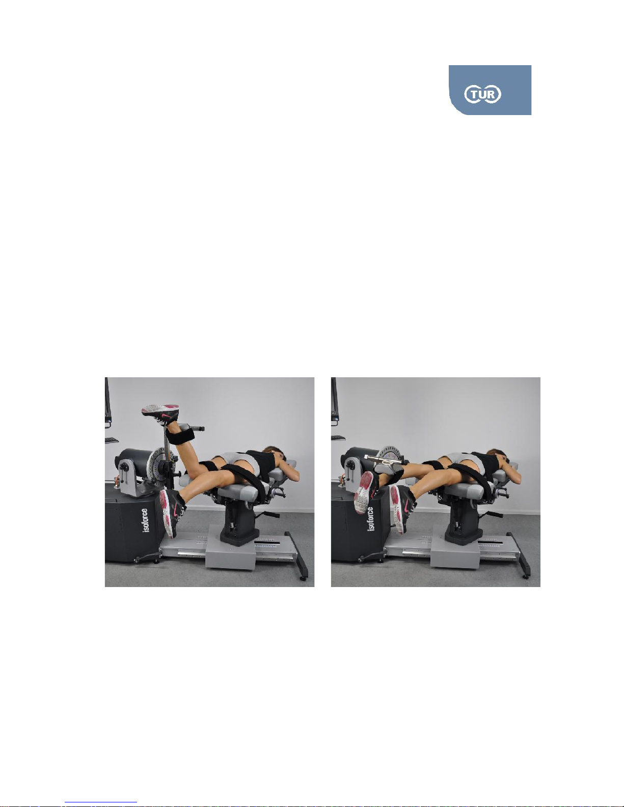
Prone Position / this positioning ensures a wider ROM
Attachments Needed
Dynamometer: Knee Adaptor (ADL3) with single or double knee pad
Page 43

5.2.1 User Manual Isoforce
REV 5 01st July 2014 page 43 von 77
TUR Therapietechnik GmbH | Grubenstr. 20 | 18055 Rostock | Germany
Set up & positioning
Put the mechanical stops to “B” blue and “B” red.
Collect the Knee attachment.
Attach Knee Adapter to the dynamometer by sliding it in the input arm from the top, short side.
The horizontal part of the adapter should face towards the chair. Tighten it firmly by turning the
knob placed in the input arm clock wise.
Adjust the chair and the dynamometer in accordance to the quick reference above.
Ask the subject to lie on the chair.
Attach the thigh straps. Do not attach it too firmly, because the test results can be negatively
affected.
Set the axis of the joint rotation. The axis is through the lateral femoral condyle on a sagittal
plane, right opposite to the black dot on the input arm of the dynamometer. To succeed the
alignment you might need to make alterations to the positions of the chair and the
dynamometer.
Place the tibia of the subject to the centre of the knee pad. You might need to bring the chair
closer to the dynamometer. Adjust the pad to be at the top of the foot. Secure the pad at this
position, proximal to medial malleoli, using the strap.
Check the axis of rotation by asking your subject to fully extend and flex the knee.
Opposite Side
Unstrap patient's knee from attachment.
While the patients still lays on the chair, slide the chair away from the dynamometer.
Remove the knee attachment from the dynamometer input arm and put it back turning it
around.
Adjust the chair and the dynamometer in accordance to the quick reference above.
Follow the steps 6 -10 as described above.
3.3.2 Knee Internal-External Rotation
Rotation Axis: Through the center of the calcaneus
Anatomical Zero: Straight leg in neutral position
Range of Motion: The ROM is between 30-50 degrees internal rotation and 20-40 degrees external
rotation
Page 44
5.2.1 User Manual Isoforce
REV 5 01st July 2014 page 44 von 77
TUR Therapietechnik GmbH | Grubenstr. 20 | 18055 Rostock | Germany
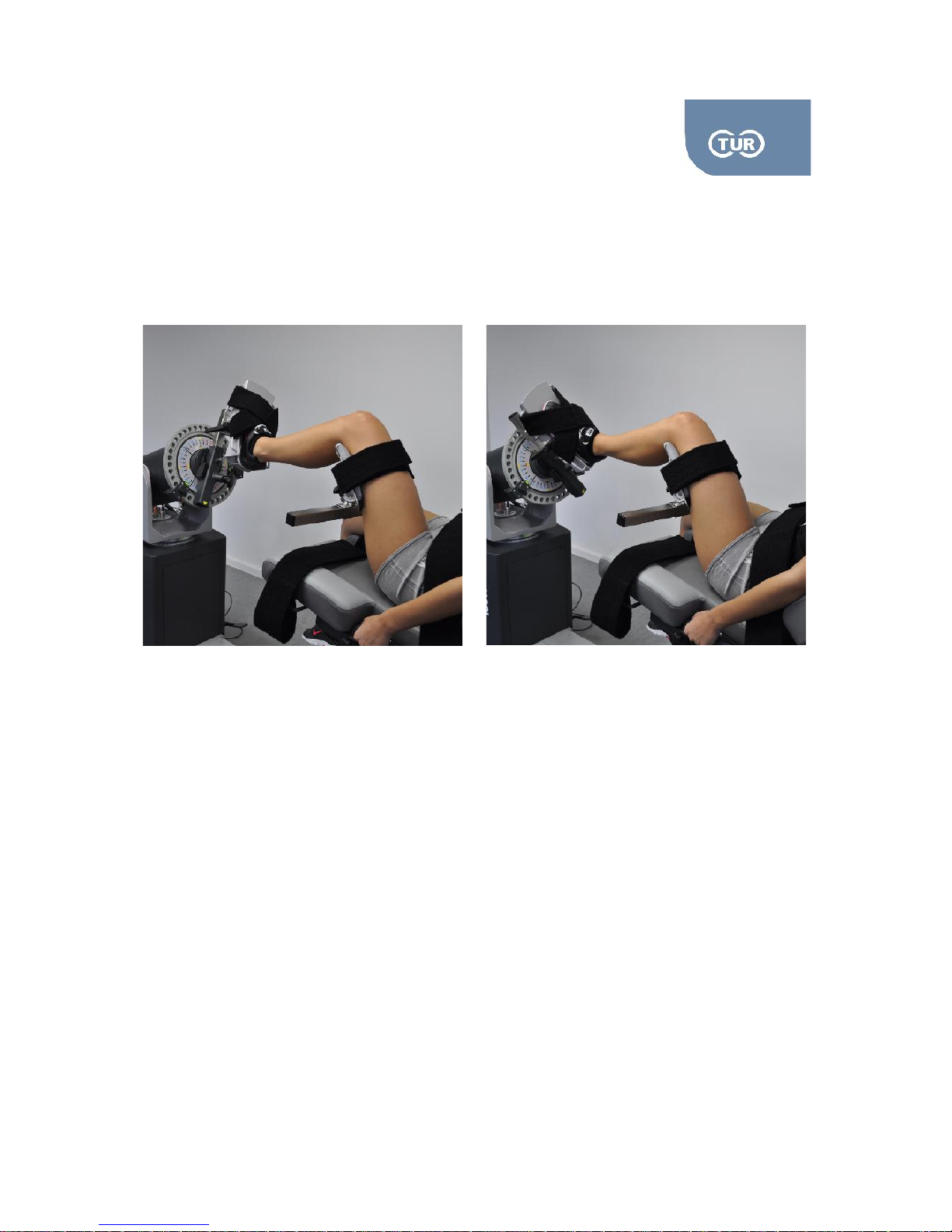
Isoforce offers one positioning possibility, in supine position. This position looks like the ankle
inversion/eversion. However, during the tibial rotation the knee should be flexed to 90 degrees. Make
sure that the foot of your subject is not lifted from the ankle plate during the movement.
Muscles Involved: Semimembranosus, semitendinosus, and popliteus do internal rotation, and biceps
femoris does external rotation.
Attachments Needed
Dynamometer: Ankle attachment (ADA1),
Seat: Angle Attachment (ADS1), Thigh Pad (ADS4)
Set up & positioning
Put the mechanical stops to “B” red and “B” red.
Attach the ankle (ADA1) to the dynamometer by sliding it in the input arm from the top, short side.
Tighten it firmly by turning the knob placed in the input arm clock wise.
For the seated position combine the ADS1 with the ADS4 and place it in the receiving tube of the
seat by sliding it from the top. Tighten it firmly by turning the knob placed in the input arm clock
wise. The attachment should be facing the leg to be tested. Set it low as it is much easier to adjust
it higher if needed. Insert the thigh pad stabilizer in the vertical angle with its vertical section
towards the inside. Secure firmly.
Ask the subject to lay on the chair facing the dynamometer.
Place the subject's ankle in the ankle adapter and secure it firmly by tightening the straps.
Page 45

5.2.1 User Manual Isoforce
REV 5 01st July 2014 page 45 von 77
TUR Therapietechnik GmbH | Grubenstr. 20 | 18055 Rostock | Germany
The stabilizer of the thigh should be just above the posterior joint line. Secure it with the strap. Do
not over tighten it. Tip! Set the dynamometer in approximately 55 degrees tilt before you position
the subject and position the ADS4 in a way that the subject can put the ankle on the foot plate.
Set the axis of the joint rotation. The axis of rotation goes from the machine and extends through
the centre of calcaneus.
Opposite Side
Unstrap patient's thigh from the stabilizer, as well as his/her ankle.
Slide the chair away from the dynamometer.
Remove the seat attachments and place them the other way around, the angle should face the
other side.
Adjust the chair and the dynamometer.
Follow the steps 5 -8 as described above.
Page 46
5.2.1 User Manual Isoforce
REV 5 01st July 2014 page 46 von 77
TUR Therapietechnik GmbH | Grubenstr. 20 | 18055 Rostock | Germany
3.4 Shoulder
The shoulder is a complex joint made up of many articulations capable of a wide variety of motions. The
shoulder complex is made up of the clavicle, the humerus, the sternum, the scapula, the ribs, and the
vertebral column (Rybski, 2004). The distinctive feature about the shoulder is that it is tied and
connected to the whole body and interacts with back and chest muscles. The shoulder joint consists of
a combined and coordinated movement of four distinct articulations - glenhumeral, arcomioclavicular,
sternoclavicular, and scapulothoracic - which allow the arm to be positioned in space for efficient
function (Nordin & Frankel, 1989). The four articulations of the shoulder joint complex acting together to
provide the nearly full range of motion found in the shoulder, the sum of which is greater than the
motion available at any single articulation. Of the four articulations, the glenhumeral joint bears the
greatest load (Nordin & Frankel, 1989). The mobility of the shoulder joint is a result of motion in both
glenhumeral joint and scapulothoracic-gliding plane (Veeger & Van der Helm, 2007).
3.4.1 Flexion – Extension (Supine)
Rotation Axis: a point roughly 2-3 cms below the inferior lip of the acromial arch. However, one should
keep in mind the gleno-humeral joint as a whole moves by an average of 8cm throughout a
movement, therefore the need for accuracy is seriously questioned.
Anatomical Zero: In neutral position with arms at the side of the body
Range of Motion: The normal ROM is between up to 180 degrees extension
And 60 degrees flexion
Isoforce offers one positioning possibility, in supine position.
Muscles Involved: Pectoralis major, Deltoid, biceps, coracobrachialis, latissimus dorsi, teres major
Page 47
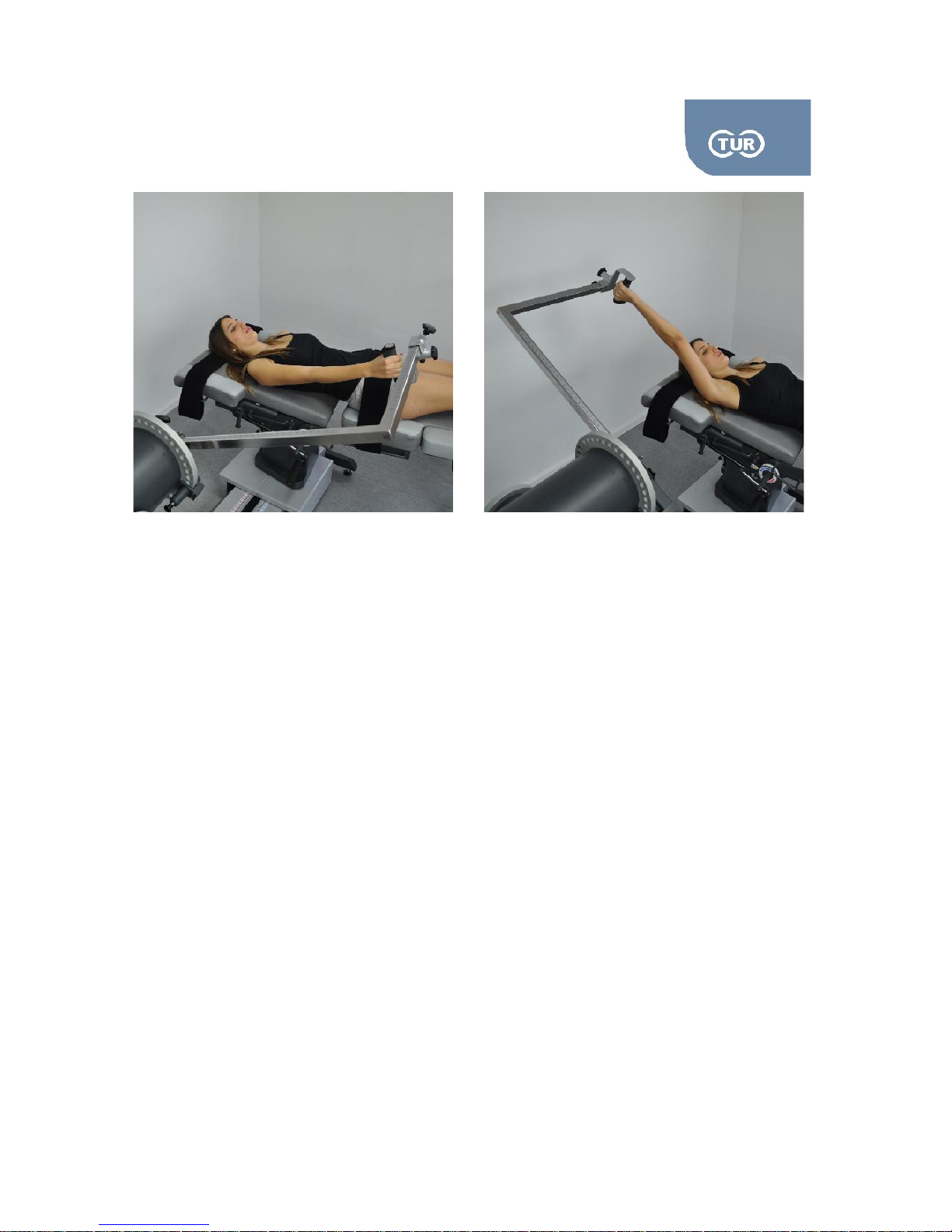
5.2.1 User Manual Isoforce
REV 5 01st July 2014 page 47 von 77
TUR Therapietechnik GmbH | Grubenstr. 20 | 18055 Rostock | Germany
Attachments Needed
Dynamometer: Angle Adapter ADL4 and Wrist Adapter ADW1
Chair: Footrest, which is a combination of ADS1 and ADT2 (optional)
Put the mechanical stops to “B” blue and “B” red.
Collect angle ADL4 attachment and the handle grip. Combine them to form the attachment
shown in the picture above.
Attach the combined adapter to the dynamometer by sliding it in the input arm, short side.
Ask the subject to lay on the chair.
Set the axis of the joint rotation. The axis of rotation for shoulder is through the acromium, and
it should be right opposite to the colored dot on the input arm of the dynamometer. To succeed
the alignment you might need to make alterations to the positions of the chair and the
dynamometer. The attachment should be parallel to the subject's trunk.
Ask the subject to hold the handle and adjust the length of the attachment. The best angle to
make this adjustment is a few degrees from full extension.
Check the axis of rotation by asking your subject to perform a full flexion and extension of
his/her shoulder.
Opposite Side
Ask the subject to stop holding the attachment.
While the subject still lays on the chair, slide the chair away from the dynamometer.
Page 48
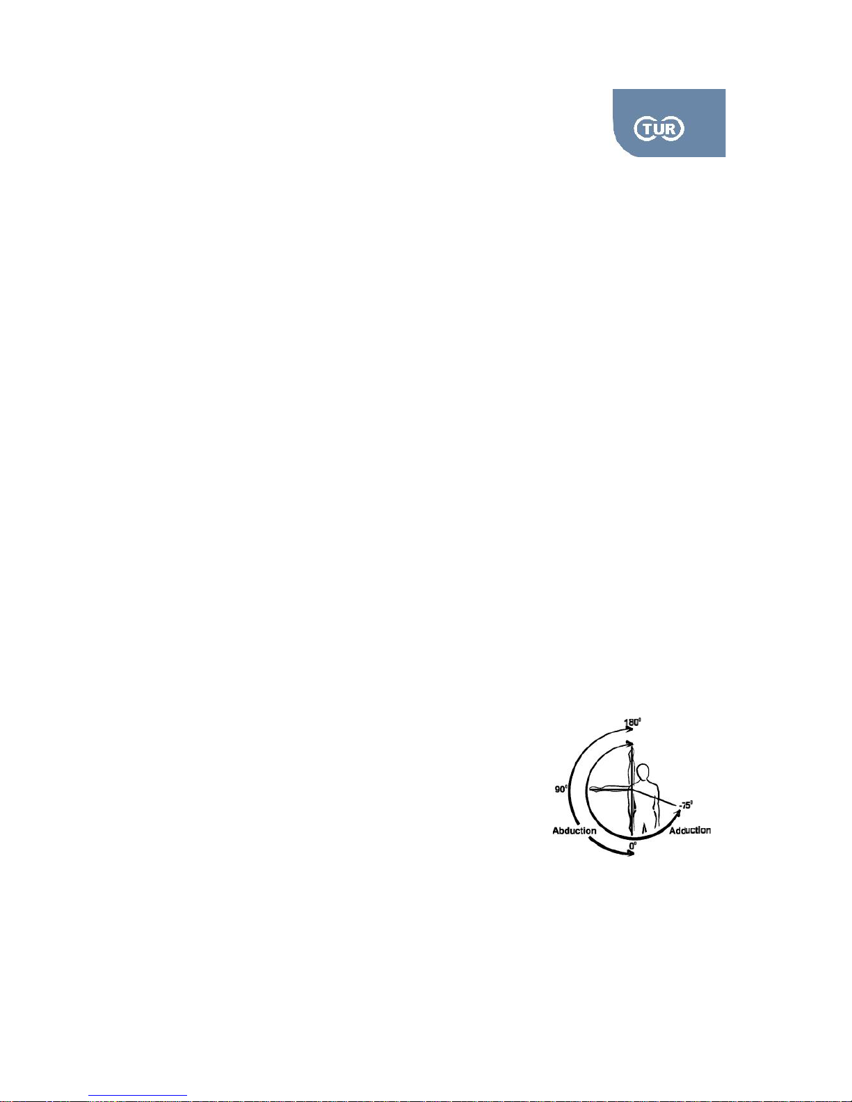
5.2.1 User Manual Isoforce
REV 5 01st July 2014 page 48 von 77
TUR Therapietechnik GmbH | Grubenstr. 20 | 18055 Rostock | Germany
Remove the shoulder attachment from the dynamometer input arm and put it back turning it
around.
Adjust the chair and the dynamometer in accordance to the quick reference above.
Follow the steps 5-7 as described above.
Considerations
Flexion/Extension of the shoulder is usually used in the early stages of rehabilitation. However,
the therapist should be careful not to cause impingement. To avoid this limit the flexion ROM.
Generally it is accepted that speeds of 60 degrees/second and multiples of this should be used.
Speeds over 300 degrees/second have been found to be difficult to achieve by even baseball
pitchers.
The axis of rotation may superior move during this exercise. To avoid this you can divide the
ROM in two, and perform two tests instead of one. One test could be the external ROM and
one the internal.
Flexion beyond 900produces high variability in results.
Gravity Correction is necessary for reliable test results as the movement is performed in the
vertical plane.
In the anterior impingement syndrome a rapid drop in torque at the start of the range of motion
3.4.2 Adduction – Abduction (Laying)
Rotation Axis: a point roughly 2-3 cms below the inferior lip of the acromial arch. However, one should
keep in mind the gleno-humeral joint as a whole moves by an average of 8cm throughout a
movement, therefore the need for accuracy is seriously questioned.
Anatomical Zero: In neutral position with arms at the side of the body
Range of Motion: The normal ROM is between up to 180 degrees
adduction and 75 degrees abduction
Isoforce offers one positioning possibility, in supine position.
Muscles Involved: Teres major, latissimus dorsi, Pectoralis major, Middle, Anterior and posterior deltoid
Page 49
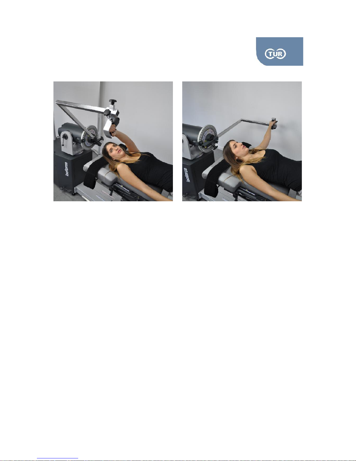
5.2.1 User Manual Isoforce
REV 5 01st July 2014 page 49 von 77
TUR Therapietechnik GmbH | Grubenstr. 20 | 18055 Rostock | Germany
Laying
Attachments Needed
Dynamometer: Angle Adapter ADL4 and Wrist Adapter ADW1
Chair: Footrest, which is a combination of ADS1 and ADT2 (optional)
Put the mechanical stops to “B” blue and “B” red.
Collect angle/elbow attachment and the handle grip. Combine them to form the attachment
shown above
Attach the adapter to the dynamometer by sliding it in the input arm from the top, short side
Ask the subject to lay supine on the chair.
The shoulder to be tested should be on top. Subject should face away from the dynamometer.
Set the axis of the joint rotation. The axis of rotation for shoulder is through the acromiom, and
it should be right opposite to the colored dot on the input arm of the dynamometer. To succeed
the alignment you might need to make alterations to the positions of the chair and the
dynamometer.
Ask the subject to hold the handle and adjust the length of the attachment.
Check the axis of rotation by asking your subject to perform a full adduction/abduction of
his/her shoulder.
Page 50
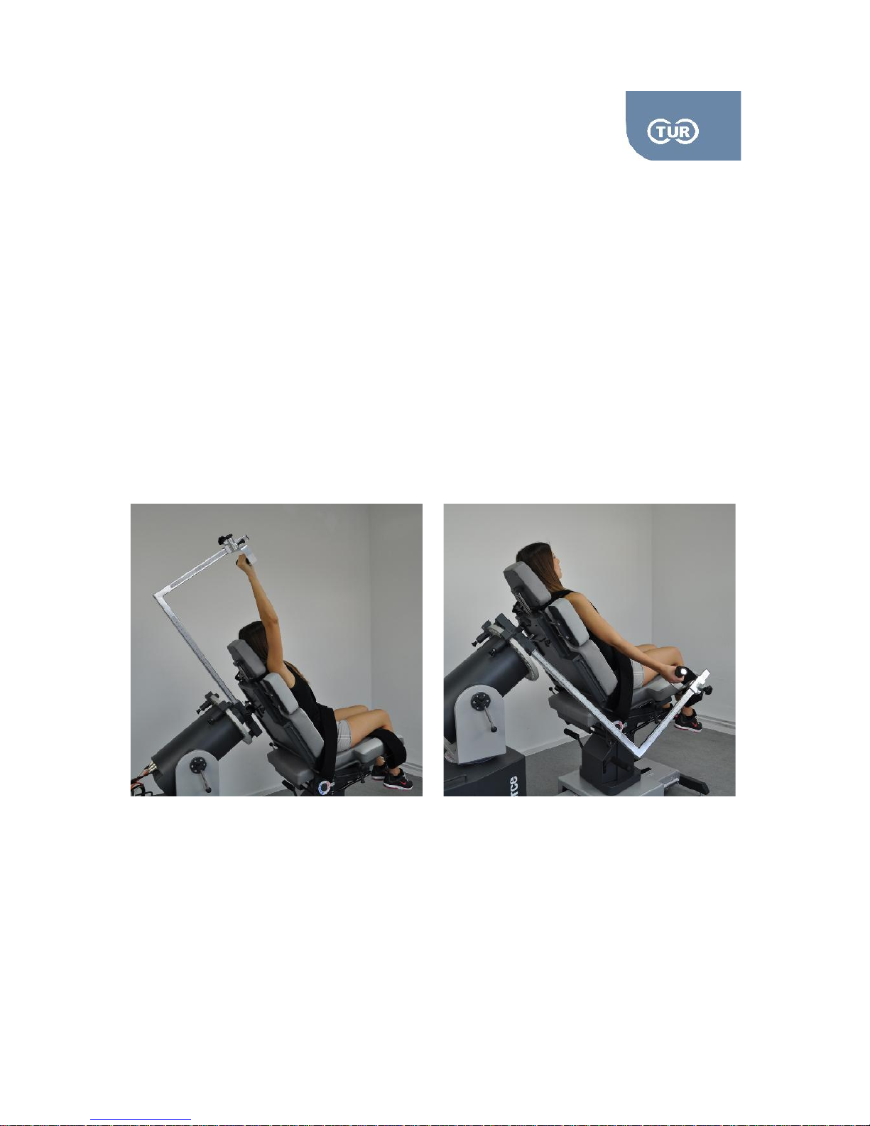
5.2.1 User Manual Isoforce
REV 5 01st July 2014 page 50 von 77
TUR Therapietechnik GmbH | Grubenstr. 20 | 18055 Rostock | Germany
Opposite Side
Ask the subject to stop holding the attachment.
While the subject still lays on the chair, slide the chair away from the dynamometer.
Remove the shoulder attachment from the dynamometer input arm and put it back turning it
around.
Adjust the chair and the dynamometer in accordance to the quick reference above.
Follow the steps 6 -9 as described above.
Seated Position
Attachments Needed
Dynamometer: Angle Adapter ADL4 and Wrist Adapter ADW1
Chair: Footrest, which is a combination of ADS1 and ADT2 (optional)
Put the mechanical stops to “B” blue and “B” red.
Collect angle/elbow attachment and the handle grip. Combine them to form the attachment shown
in the photo.
Attach the adapter to the dynamometer by sliding it in the input arm from the top, short side.
.
Page 51

5.2.1 User Manual Isoforce
REV 5 01st July 2014 page 51 von 77
TUR Therapietechnik GmbH | Grubenstr. 20 | 18055 Rostock | Germany
Ask the subject to seat on the positioning chair.
The shoulder to be tested should be on top. Subject should face away from the dynamometer.
Set the axis of the joint rotation. The axis of rotation for shoulder is through the acromiom, and it
should be right opposite to the colored dot on the input arm of the dynamometer. To succeed the
alignment you might need to make alterations to the positions of the chair and the dynamometer.
Ask the subject to hold the handle and adjust the length of the attachment.
Check the axis of rotation by asking your subject to perform a full adduction/abduction of his/her
shoulder.
Opposite Side
Ask the subject to stop holding the attachment.
While the subject still lies on the chair, slide the chair away from the dynamometer.
Remove the shoulder attachment from the dynamometer input arm and put it back turning it
around.
Adjust the chair and the dynamometer
Follow the steps 6 -8 as described above.
3.4.3. Shoulder Horizontal Adduction/Abduction, Supine
Rotation Axis: a point roughly 2-3 cms below the inferior lip of the acromial arch. However, one should
keep in mind the gleno-humeral joint as a whole moves by an average of 8cm throughout a
movement, therefore the need for accuracy is seriously questioned.
Anatomical Zero: In neutral position with arms at the side of the body
Range of Motion: The normal ROM is between up to 180 degrees adduction and 75 degrees abduction
Isoforce offers one positioning possibility, in supine position.
Muscles Involved: Teres major, latissimus dorsi, Pectoralis major, Middle, Anterior and posterior deltoid
Page 52

5.2.1 User Manual Isoforce
REV 5 01st July 2014 page 52 von 77
TUR Therapietechnik GmbH | Grubenstr. 20 | 18055 Rostock | Germany
Attachments Needed
Dynamometer: Angle Adaptor (COMB05) comprised of AD008+AD012
Put the mechanical stops to “B” blue and “B” red.
Collect angle/elbow attachment and the handle grip. Combine them to form the attachment
COMB05.
Attach the COMB05 to the dynamometer by sliding it in the input arm.
Adjust the chair and the dynamometer in accordance to the quick reference above.
Ask the subject to lay on the positioning chair.
Ask the subject to hold the handle and bring his/her shoulder in 90° flexion.
Set the axis of the joint rotation. The axis of rotation for shoulder is through the acromiom, and it
should be right opposite to the coloured dot on the input arm of the dynamometer. To succeed
the alignment you might need to make alterations to the positions of the chair and the
dynamometer.
The length of the attachment might need to be adjusted.
Check the axis of rotation by asking your subject to perform a horizontal abduction and adduction
movement.
Opposite Side
Ask the subject to leave the handle.
While the subject still lays on the chair, slide the chair away from the dynamometer.
Remove the shoulder attachment from the dynamometer input arm and put it back turning it
around.
Adjust the chair and the dynamometer in accordance to the quick reference above.
Follow the steps 6 -9 as described above.
Considerations
The movement is performed more comfortable if the elbow is not fully flexed
Page 53
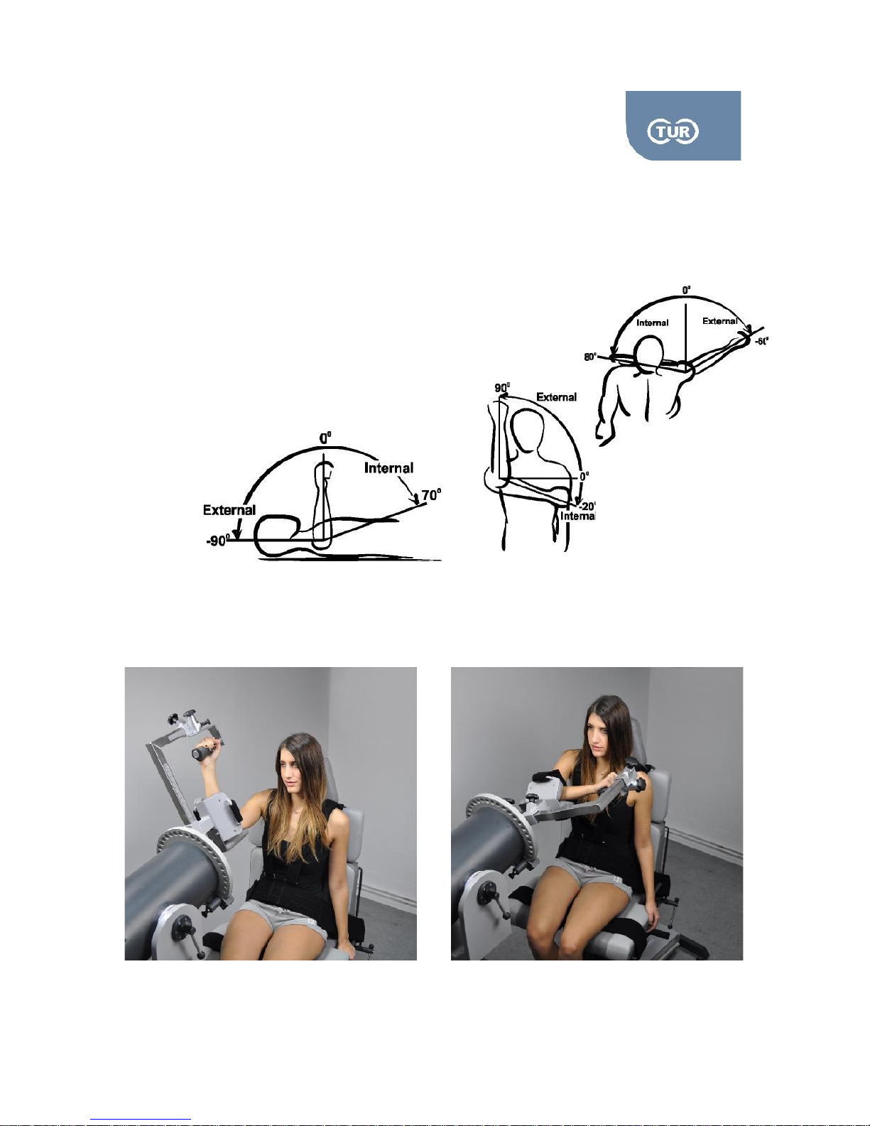
5.2.1 User Manual Isoforce
REV 5 01st July 2014 page 53 von 77
TUR Therapietechnik GmbH | Grubenstr. 20 | 18055 Rostock | Germany
3.4.3 Internal External Rotation Patterns
Rotation Axis: be co-linear with that of the humerus through the olecranon.
Anatomical Zero: Mid way between internal and external rotation
Range of Motion: Different ROMs are normal for the different positioning
Possibilities. Use the pictures as reference.
Isoforce offers different positioning, in 90 degrees adduction, in 90 degrees
flexion, the modified 45 degrees adduction and in standing
position.
Muscles Involved: Teres major, latissimus dorsi, Pectoralis major, Middle, Anterior and posterior deltoid
Internal External Rotation Abd 90°
Page 54
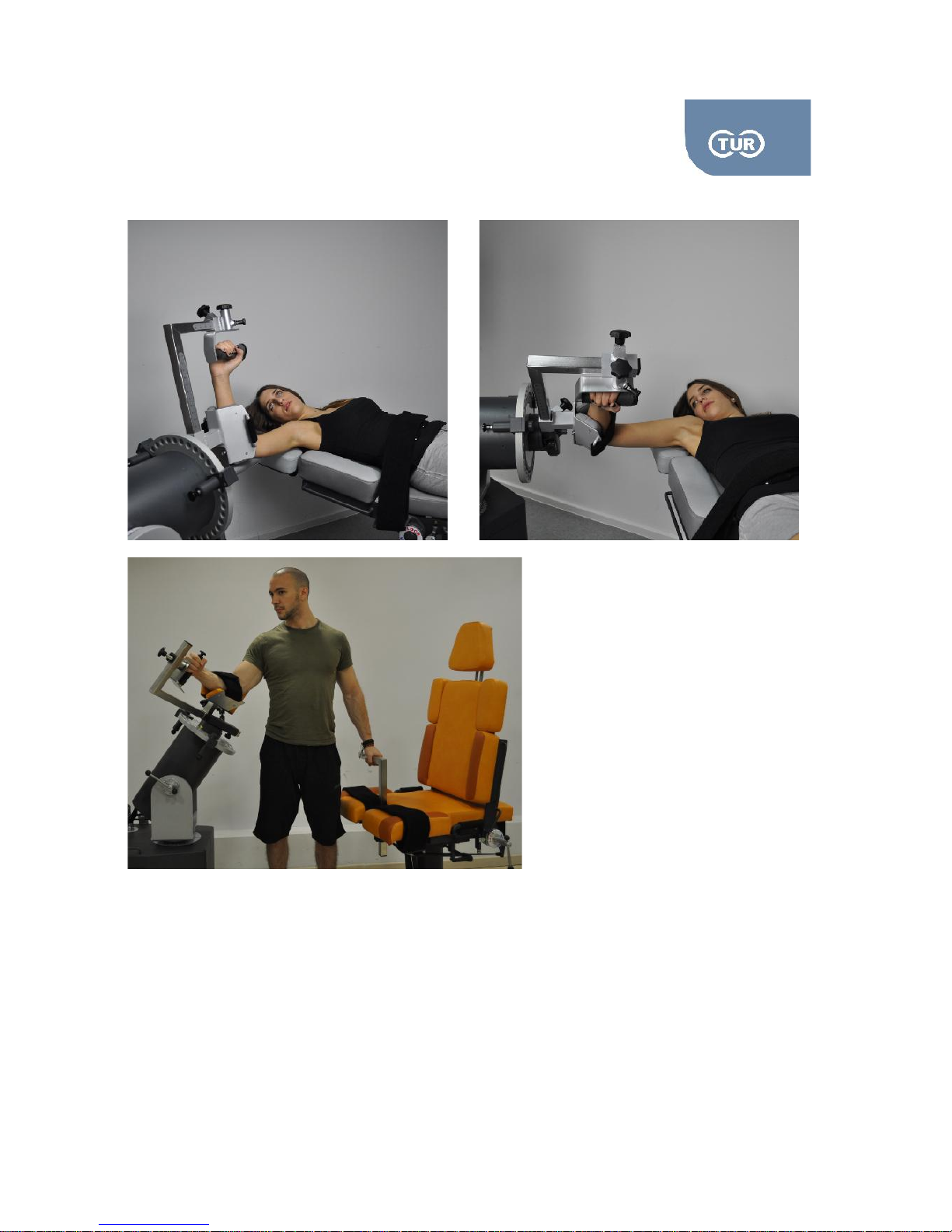
5.2.1 User Manual Isoforce
REV 5 01st July 2014 page 54 von 77
TUR Therapietechnik GmbH | Grubenstr. 20 | 18055 Rostock | Germany
Attachments Needed
Dynamometer: AAL01, ADW1 and ADS3
Put the mechanical stops to “E” blue and “E” red.
Collect angle/elbow attachment and the handle grip and combine them as shown in the picture
above
Page 55

5.2.1 User Manual Isoforce
REV 5 01st July 2014 page 55 von 77
TUR Therapietechnik GmbH | Grubenstr. 20 | 18055 Rostock | Germany
Attach the adapter to the dynamometer by sliding it in the input arm from the top.
Ask the subject to lay on the positioning chair or seat on the chair.
Ask the subject to hold the grip and position the forearm in the stabilizer. Tighten the strap. Adjust
the stabilizer-hand grip distance.
Set the axis of the joint rotation. To achieve the alignment make sure the forearm is parallel to the
dynamometer input adaptor. To succeed the alignment you might need to make alterations to the
positions of the chair and the dynamometer.
Be careful not to lose the 90° abduction angle of the shoulder, while trying to achieve the alignment.
Use a goniometer to check the angle.
Check the axis of rotation by asking your subject to perform an internal rotation followed by an
external one.
Opposite Side
Release your subject's forearm by unstrapping the stabilizer's belt. Instruct your subject to stop
handling the grip.
While the subject still lays on the chair, slide the chair away from the dynamometer.
Adjust the chair and the dynamometer to align the dynamometer axis with the joint rotation axis
Follow the steps 6 -8 as described above.
Page 56
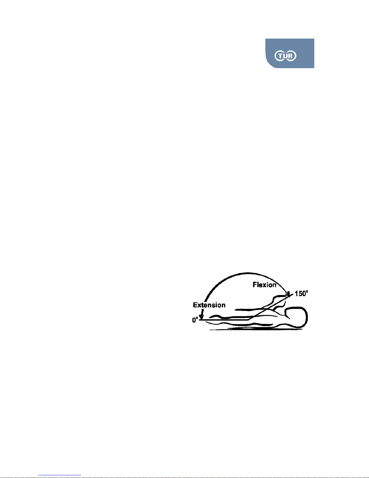
5.2.1 User Manual Isoforce
REV 5 01st July 2014 page 56 von 77
TUR Therapietechnik GmbH | Grubenstr. 20 | 18055 Rostock | Germany
3.5 Elbow
The elbow joint occurs at the junction the humerus or upper arm bone, the ulna which is the larger of
the two forearm bones and the radius bone. The humerus forms the upper part of the joint and widens
near the end to form the medial and lateral epicondyles which are the two bony processes felt either
side of the elbow joint.
The ulna is situated on the inside of the joint and forms a cup shape which allows articulation with the
humerus. The radius is the smaller of the two forearm bones and sits on the outside of the joint. The
radial head is round and again cup-shaped to allow it to move around the wide base known as the
capitulum of the humerus.
There are actually three joints at the elbow. The first being the hinge joint formed between the humerus
and the ulna called the humeroulnar joint, which allows us to bend and straighten our elbows.
The second is the humeroradial joint between the radius and humerus which again allows flexion and
extension but is also involved in the more complex motion of turning the hand over so the palm faces
up or down. This movement of the forearm is called supination (palm up) and pronation (palm down).
The third is a pivot joint formed by the radius and ulna and is called the proximal radioulna joint.
3.5.1 Elbow Extension – Flexion
Rotation Axis:. Approximately 1 cm above the lateral epicondyle
Anatomical Zero: Straight Arm
Range of Motion: Up to 150 degreed flexion
Isoforce offers one positioning possibility, in supine position.
Muscles Involved: Brachialis and brachioradialis
Page 57
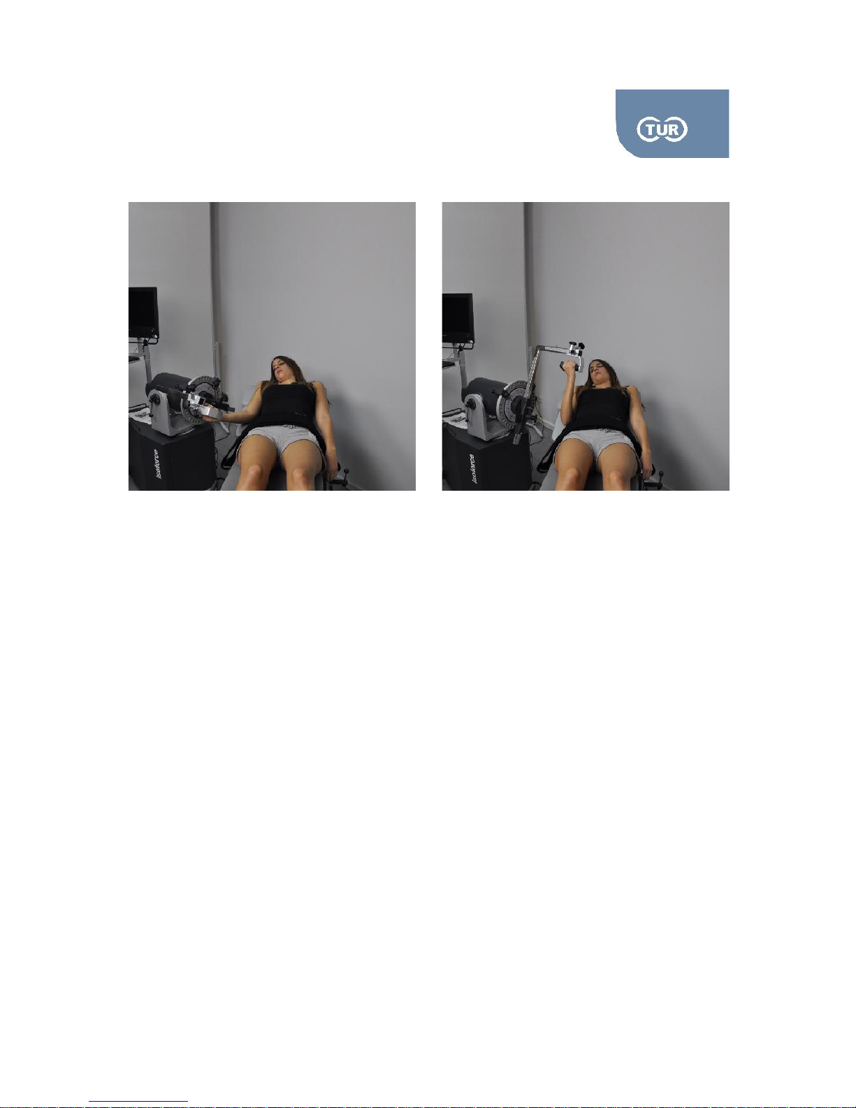
5.2.1 User Manual Isoforce
REV 5 01st July 2014 page 57 von 77
TUR Therapietechnik GmbH | Grubenstr. 20 | 18055 Rostock | Germany
Attachments Needed
Dynamometer: AAL02, ADW1
Put the mechanical stops to “B” blue and “B” red.
Collect angle/elbow attachment and the handle grip and combine them as shown in the picture
above
Attach the adapter to the dynamometer by sliding it in the input arm from the top.
Ask the subject to lay on the positioning chair or seat on the chair.
Ask the subject to hold the grip.
Set the axis of the joint rotation. To achieve the alignment make sure the forearm is parallel to the
dynamometer input adaptor. To succeed the alignment you might need to make alterations to the
positions of the chair and the dynamometer.
Check the axis of rotation by asking your subject to perform full elbow flexion
Page 58
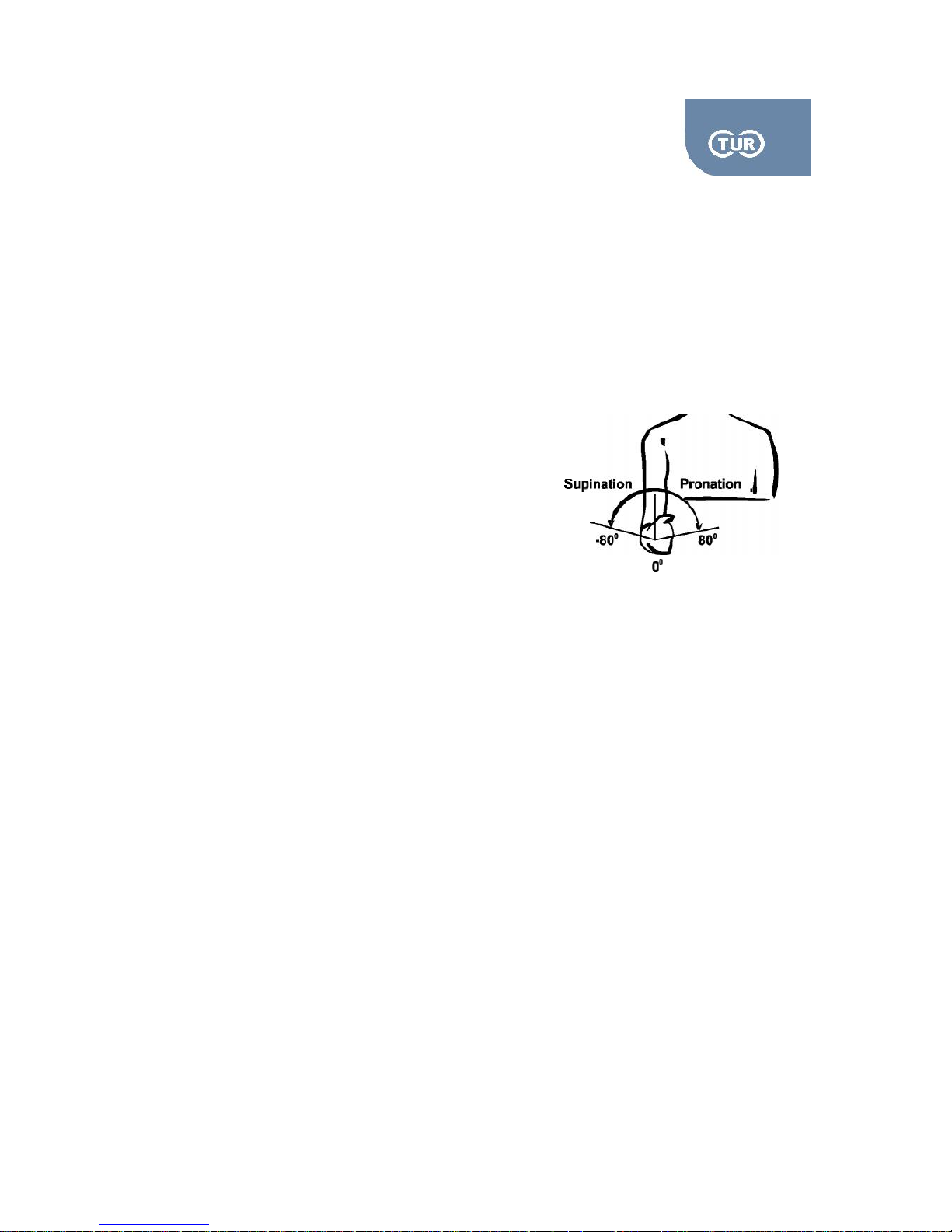
5.2.1 User Manual Isoforce
REV 5 01st July 2014 page 58 von 77
TUR Therapietechnik GmbH | Grubenstr. 20 | 18055 Rostock | Germany
Opposite Side
While the subject still lays on the chair, slide the chair away from the dynamometer and rotate the
former to the other side
Adjust the chair and the dynamometer to align the dynamometer axis with the joint rotation axis
3.5.2 Pronation – Supination
Rotation Axis:. The axis of rotation bisects the head of the ulna distally
and the head of the radius proximally.
Anatomical Zero: Thumb pointing upwards
Range of Motion: Normal ROM is 80 degrees in pronation and
80 degrees in supination. However a ROM of 30/0/30is considered
Adequate for isokinetic testing
Isoforce offers one positioning possibility, in seated position.
Muscles Involved: Pronator teres and pronator quadratus are responsible for the pronation. The
muscles that supinate the forearm are biceps brachii, brachioradialis, and the supinator.
Page 59

5.2.1 User Manual Isoforce
REV 5 01st July 2014 page 59 von 77
TUR Therapietechnik GmbH | Grubenstr. 20 | 18055 Rostock | Germany
Attachments Needed
Dynamometer: AAL02, ADW1
Put the mechanical stops to “B” blue and “B” red.
Collect angle/elbow attachment and the handle grip and combine them as shown in the picture
above
Attach the adapter to the dynamometer by sliding it in the input arm from the top.
Ask the subject to lay on the positioning chair or seat on the chair.
Ask the subject to hold the grip.
Set the axis of the joint rotation. To achieve the alignment make sure the forearm is parallel to the
dynamometer input adaptor. To succeed the alignment you might need to make alterations to the
positions of the chair and the dynamometer.
Check the axis of rotation by asking your subject to perform full elbow flexion
Opposite Side
While the subject still lays on the chair, slide the chair away from the dynamometer and rotate the
former to the other side
Adjust the chair and the dynamometer to align the dynamometer axis with the joint rotation axis
Page 60
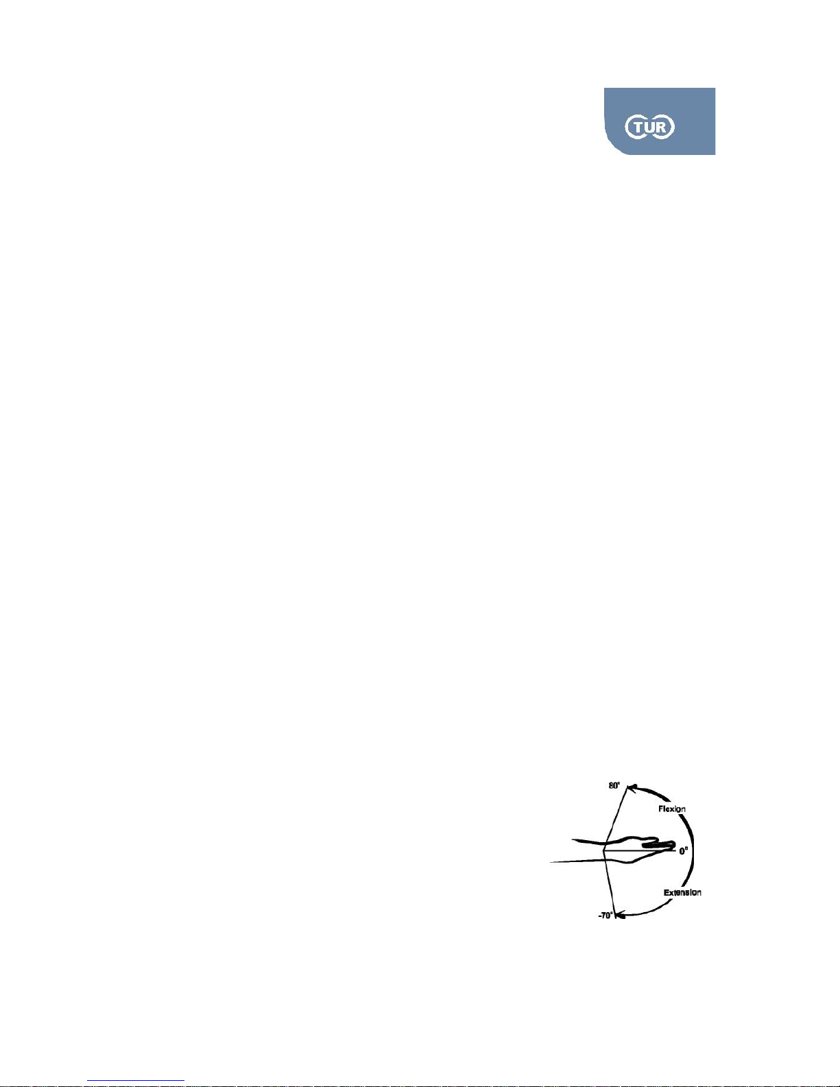
5.2.1 User Manual Isoforce
REV 5 01st July 2014 page 60 von 77
TUR Therapietechnik GmbH | Grubenstr. 20 | 18055 Rostock | Germany
3.6 Wrist
The bones of the hand and wrist provide the body with support and flexibility to manipulate objects in
many different ways. Each hand contains 27 distinct bones that give the hand an incredible range and
precision of motion. The forearm's ulna and radius support the many muscles that manipulate the
bones of the hand and wrist. Rotation of the radius around the ulna results in the supination and
pronation of the hand. These bones also form the flexible wrist joint with the proximal row of the
carpals
There are eight small carpal bones in the wrist that are firmly bound in two rows of four bones each.
The mass that results from these bones is called the carpus. The carpus is rounded on its proximal end,
where it articulates with the ulna and radius at the wrist. The carpus is slightly concave on the palmar
side, forming a canal known as the carpal tunnel through which tendons, ligaments, and nerves extend
into the palm. Its distal surface articulates with the metacarpal bones, which are joined to the carpus by
the palmar carpometacarpal ligaments.
The five long, thin metacarpal bones of the palm extend from the carpus to each of the digits of the
hand. Each metacarpal is numbered I to V with metacarpal I connecting to the bones of the thumb, II
connecting to the index finger, III connecting to the ring finger, and so on. Movement of the metacarpals
by tiny muscles in the hand allows the palm to be stretched, compressed, and folded as needed. The
distal head of the metacarpals is rounded to form a condyloid (oval) joint with the phalanges of the
fingers. These condyloid joints allow 360-degree motion of the fingers at their bases.
Each of the digits of the hands contains 3 phalanges (singular: phalanx) except for the thumbs that
contain only 2. The phalanges are long, slender bones that form hinge joints between each other.
Phalanges that articulate with the metacarpals at the base of the digits are known as the proximal
phalanges. The phalanges at the end of each digit are called the distal phalanges. In all of the digits
except for the thumb the middle phalanges are found between the proximal and distal phalanges.
Muscles in the forearms flex and extend the phalanges by pulling on long tendons that run through the
wrist and hand.
3.6.1 Flexion / Extension
Rotation Axis: It is slightly oblique through the wrist just distal to the
tubercle of the radius and the head of the ulna
Anatomical Zero: The wrist is parallel to the forearm
Range of Motion: Normal ROM is 80 degrees for flexion and 70 degrees for
Page 61
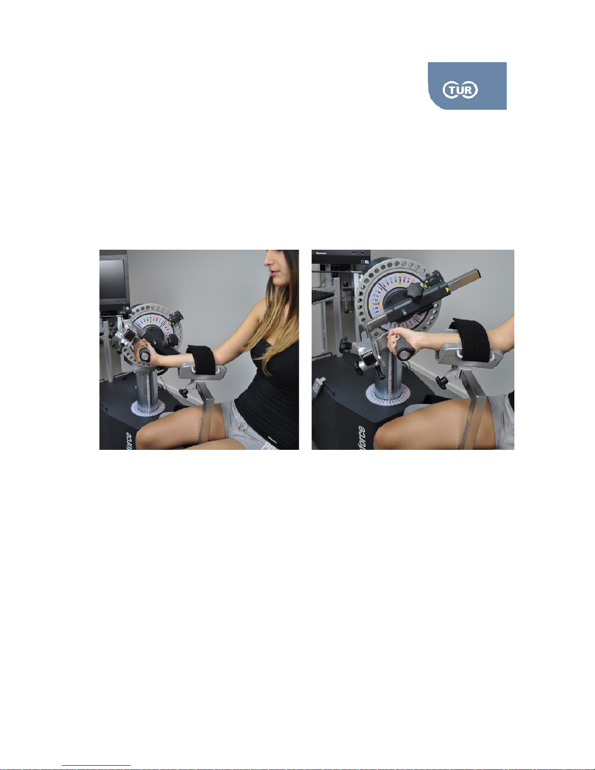
5.2.1 User Manual Isoforce
REV 5 01st July 2014 page 61 von 77
TUR Therapietechnik GmbH | Grubenstr. 20 | 18055 Rostock | Germany
Extension, however optimal ROM for the isokinetic testing of the wrist is between 40
degrees extension and 60 degrees flexion.
Isoforce offers one positioning possibility, in seated position.
Muscles Involved: The muscles that flex the hand at the wrist are the flexor carpi radialis, flexor carpi
ulnaris, and palmaris longus and the muscles that extend the hand at the wrist are the extensor carpi
radialis longus, extensor carpi radialis brevis and extensor carpi ulnaris.
Attachments Needed
Dynamometer: ADL02, ADW1
Chair: ADL01, ADS4
Put the mechanical stops to “B” blue and “B” red.
Collect angle/elbow attachment and the handle grip and combine them as shown in the picture
above
Combine ADL1 with the ADS4 and put them on the chair input adapter. The forearm stabilizer
should be at the side of the wrist to be tested.
Attach the adapter to the dynamometer by sliding it in the input arm from the top.
Ask the subject to lay on the positioning chair or seat on the chair.
Page 62
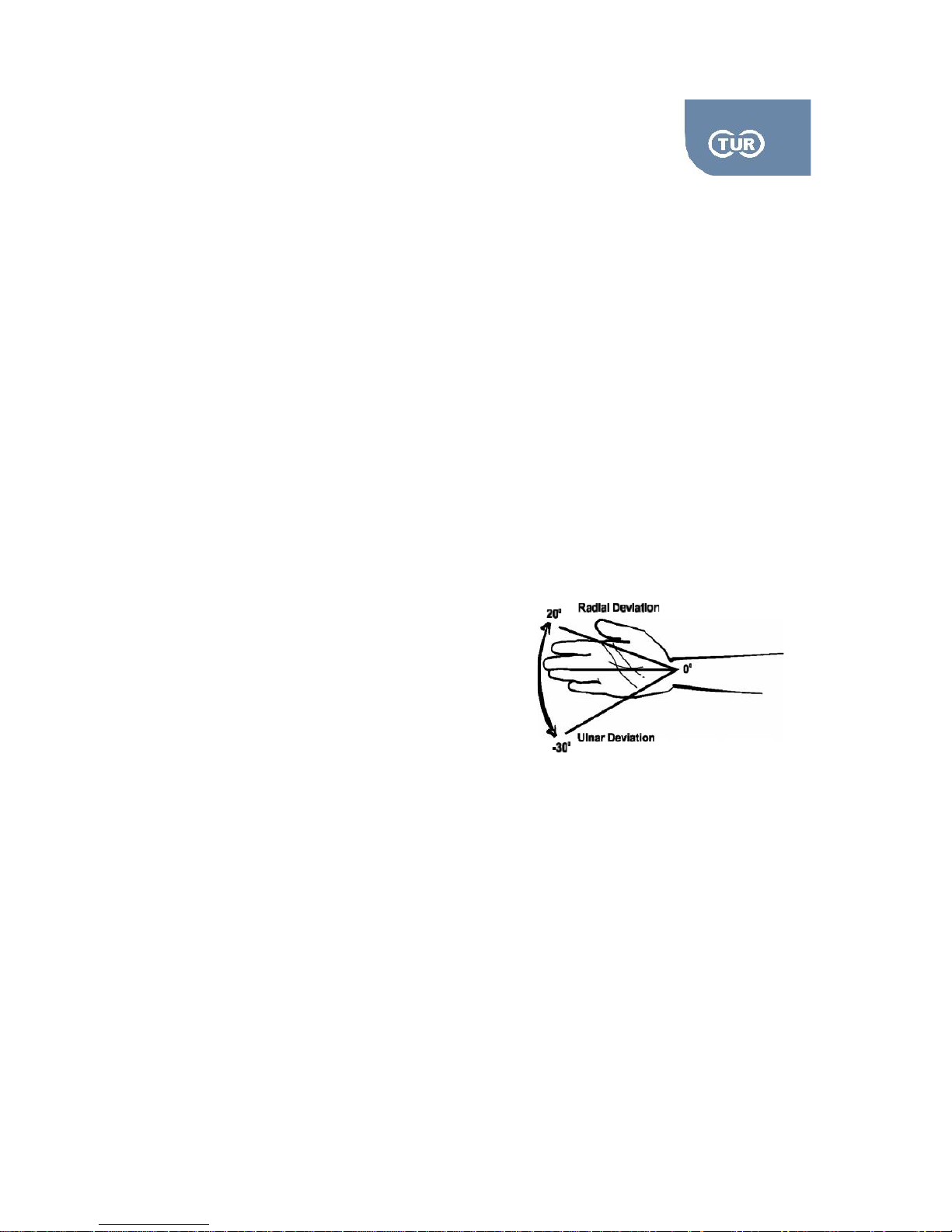
5.2.1 User Manual Isoforce
REV 5 01st July 2014 page 62 von 77
TUR Therapietechnik GmbH | Grubenstr. 20 | 18055 Rostock | Germany
Ask the subject to hold the grip.
Set the axis of the joint rotation.
Check the axis of rotation by asking your subject to perform full wrist flexion and extension
Opposite Side
Change the direction of the forearm stabilizer.
While the subject still lays on the chair, slightly rotate the dynamometer to the opposite side
Align the dynamometer axis with the joint rotation axis
3.6.2 Radial / Ulna Deviation
Rotation Axis: It is located at the center of the capitate bone
Anatomical Zero: The wrist is parallel to the forearm
Range of Motion: Normal ROM is 20 degrees for radial
deviation and 30 degrees for ulna deviation.
Isoforce offers one positioning possibility, in seated position.
Muscles Involved: Flexor carpi radialis, flexor carpi ulnaris, extensor carpi radialis longus, extensor
carpi ulnaris
Page 63
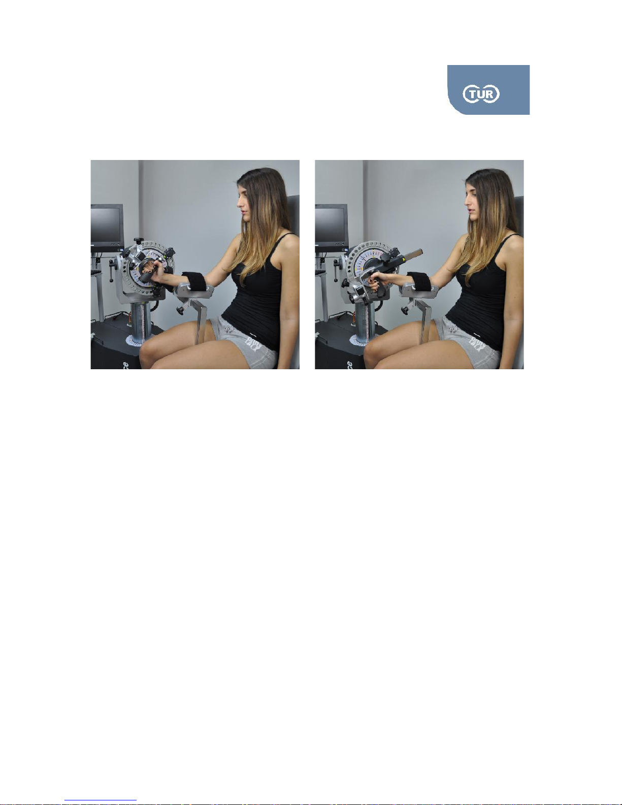
5.2.1 User Manual Isoforce
REV 5 01st July 2014 page 63 von 77
TUR Therapietechnik GmbH | Grubenstr. 20 | 18055 Rostock | Germany
Attachments Needed
Dynamometer: ADL02, ADW1
Chair: ADL01, ADS4
Put the mechanical stops to “B” blue and “B” red.
Collect angle/elbow attachment and the handle grip and combine them as shown in the picture
above
Combine ADL1 with the ADS4 and put them on the chair input adapter. The forearm stabilizer
should be at the side of the wrist to be tested.
Attach the adapter to the dynamometer by sliding it in the input arm from the top.
Ask the subject to lay on the positioning chair or seat on the chair.
Ask the subject to hold the grip.
Set the axis of the joint rotation.
Check the axis of rotation by asking your subject to perform full wrist ulnar and radial deviation.
Page 64

5.2.1 User Manual Isoforce
REV 5 01st July 2014 page 64 von 77
TUR Therapietechnik GmbH | Grubenstr. 20 | 18055 Rostock | Germany
Opposite Side
Change the direction of the forearm stabilizer.
While the subject still lays on the chair, rotate the dynamometer to the opposite side
Align the dynamometer axis with the joint rotation axis
Chapter 4 - Normative Data
Page 65
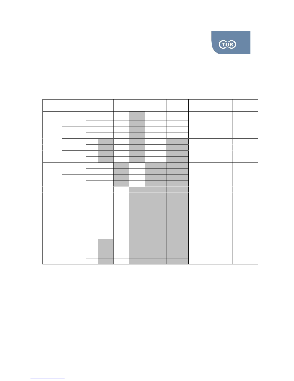
5.2.1 User Manual Isoforce
REV 5 01st July 2014 page 65 von 77
TUR Therapietechnik GmbH | Grubenstr. 20 | 18055 Rostock | Germany
1 Normative Data Lower Limb
Joint
Pattern
Sex
30/s
60/s
90/s
120/s
180/s
Ratio%
Remarks
Ankle
Dorsi
M33261812
25/30
Supine
knee full
extended
F26201512
Plantar
M
1269660
41
F84643927
Inversion
M3126
70
Lying
F2521
Eversion
M2519
F1814
Hip
Flexion
M
152
126
60
Lying
F9170
Extension
M
177
163
F
110
97
Adduction
M
121
146
40
Lying
F82207
Abduction
M
103
86
F6658
Internal
M72139
80
Lying
F4086
External
M6584
F4353
Knee
Extension
M
260
64-68
seated
F
170
Flexion
M
142
F
95
Page 66
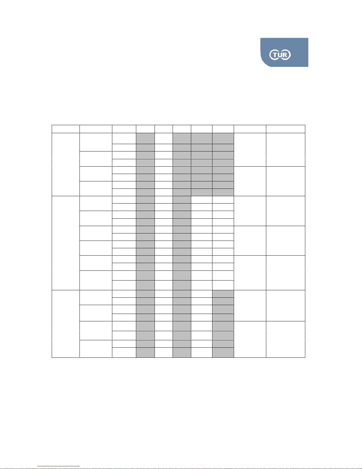
5.2.1 User Manual Isoforce
REV 5 01st July 2014 page 66 von 77
TUR Therapietechnik GmbH | Grubenstr. 20 | 18055 Rostock | Germany
4.2 Normative Data Upper Limb
Joint
Pattern
Sex
30/s
60/s
90/s
120/s
180/s
Ratio %
Remarks
Wrist
Flexion
M
6
Varying
Typical
70%ext/flex
ion
Seated
F
8
Extension
M
8
F
8,5
Radial
M
10
Varying
Typical
90%ulnar/r
adial
Seated
F
10
Ulnar
M
7,6
F
7,6
Shoulder
Flexion
M6459
55
65
Lying
F3235
31
Extension
M
1008384
F4938
45
Abduction
M5350
43
50/55
Lying
F2827
19
Adduction
M9971
86
F5132
45
Internal
M5540
49
60/65
Seated
F2826
23
External
M3323
27
F1915
13
ElbowForearm
Flexion
M4229
90
Seated
F2115
Extension
M4733
F2416
Pronation
M1312
90
Seated
F87
Supination
M1110
F59
Page 67

5.2.1 User Manual Isoforce
REV 5 01st July 2014 page 67 von 77
TUR Therapietechnik GmbH | Grubenstr. 20 | 18055 Rostock | Germany
Chapter 5 - Parameters
Page 68

5.2.1 User Manual Isoforce
REV 5 01st July 2014 page 68 von 77
TUR Therapietechnik GmbH | Grubenstr. 20 | 18055 Rostock | Germany
The main parameters that are automatically calculated by the isoforce software are the
following.
Torque – force producing a rotary motion. Force applied at the axis of rotation as measured by the
dynamometer.
Peak Torque – highest muscular force output at any moment during a repetition. Indicates the muscles
maximum strength capabilities.
Mean Torque – average value of torque during the whole repetition.
Peak Torque to Body Weight – ratio displayed as a percentage of the maximum torque production to
the subjects body weight. This percentage is used to compare with normative data.
Time to Peak Torque – measure of time from start of the muscular contraction to the point of highest
torque development. An indicator of the muscle functional ability to produce force quickly.
Time from Peak to Relaxation – measure of time from the point of highest torque development to the
end of the muscular contraction. An indicator of the muscle functional ability to relax quickly.
Position of Peak Torque – point in the range of movement where peak torque is achieved. Peak torque
will usually occur at nearly the same position for similar movements and speeds.
Coefficient of Variance (CV) – ratio between the standard deviation of a data set (our data set: peak
torque values) and the mean value of that set. This is expressed as a percentage to objectively
determine the reproducibility of test data. Large percentages of coefficient of variances could be related
to underlying factors such as pain, apprehension or lack of instruction. Large muscle groups should
have a CV of 15% or below to be within normal limits and small muscle groups should be 20% or below
to be within normal limits.
Work – force multiplied by distance. Indicates the amount of tension produced by a muscle. On a graph,
work is noted as the area under the curve regardless of speed, time or range of movement.
Work to Bodyweight Ratio – ratio displayed as a percentage of the work repetition to the subjects
bodyweight.
Total Work – sum of work for every repetition performed in the exercise. Indicates the endurance
capabilities of a muscle group by evaluating the ability to maintain work.
Fatigue Index – ratio of the difference between the work carried out in the first three repetitions
compared to work in the last three repetitions. Valuable in documenting progress during endurance
training to detect the amount of fatigue throughout the exercise.
Page 69

5.2.1 User Manual Isoforce
REV 5 01st July 2014 page 69 von 77
TUR Therapietechnik GmbH | Grubenstr. 20 | 18055 Rostock | Germany
Power – work divided by the amount of time to perform that work. Calculates the amount of work
performed during a unit of time. Indicates the rate at which a muscle contracts and sustains a force
throughout the range of movement.
Average Power – amount of total work divided by time to complete that total work. Used to provide a
true measure of work rate intensity. Indicates a muscles ability to perform work over a period of time.
Important for the rehabilitation of specific activities and is usually compared bilaterally or in pre and post
testing.
Range of Motion – greatest range the joint achieved during a test.
Agonist /Antagonist Ratio – reciprocal muscle group relationship. Excessive imbalances may
predispose a joint to injury.
Deficits – deficit percentages of 1 to 10% indicate that there is no significant difference between the
muscle group. Percentages of 11 to 25% indicate that rehabilitation is recommended to improve
muscular imbalance. Negative numbers indicate that the involved extremity performed better than the
uninvolved extremity.
Page 70

5.2.1 User Manual Isoforce
REV 5 01st July 2014 page 70 von 77
TUR Therapietechnik GmbH | Grubenstr. 20 | 18055 Rostock | Germany
Chapter 6 - Cleaning and Maintenance
Page 71

5.2.1 User Manual Isoforce
REV 5 01st July 2014 page 71 von 77
TUR Therapietechnik GmbH | Grubenstr. 20 | 18055 Rostock | Germany
6.1 Cleaning
6.1.1 Data Station
The control panel of isoforce can be easily cleaned with a soft cloth dampened with water. If necessary,
you can use a liquid, non-corrosive solvent or a scratch-free cleaning agents (eg, window cleaner or
plastic cleaners).
Ensure that there is no liquid leakage in te device. Carefully dry!
6.1.2 Adapters
The adapters and the attachments can be cleaned as the device with a soft, dampened cloth. If
necessary, you can use a liquid, non-corrosive solvent or a scratch-free cleaning agents (eg, window
cleaner or plastic cleaners). On the rest of the metal surfaces avoid liquids and use a soft cloth.
6.1.3 Upholstery
The upholstery should be cleaned and disinfected in accordance to the national regulations for cleaning
components that come in contact with healthy skin. In most cases cleaning with mild alcohol containing
detergent is required.
6.2 Maintenance
Before any maintanance action the device should be disconnected from the main
TUR provides (on Request) to service companies (which are authorized bu TUR) the service manual
and related drawings.
The unit should not be opened for any reason by an unauthorized person. All maintenance and repair
work must be performed only by TUR Therapietechnik GmbH or authorized representatives.
To ensure both patient and user safety, it is necessary to follow certain maintenance procedures. They
are also necessary to maintain the safety and functional features of the system
Page 72

5.2.1 User Manual Isoforce
REV 5 01st July 2014 page 72 von 77
TUR Therapietechnik GmbH | Grubenstr. 20 | 18055 Rostock | Germany
Chapter 7 - Technical Specifications
Page 73

5.2.1 User Manual Isoforce
REV 5 01st July 2014 page 73 von 77
TUR Therapietechnik GmbH | Grubenstr. 20 | 18055 Rostock | Germany
7.1 Laser Pointer
Output Power: <1mW
Wavelength: 635-650nm
Class: II
7.2 Dynamometer Performance Specifications:
Torque Accuracy: 0,5Nm
Position Accuracy: 0,5 degrees
Speed Accuracy: ±5%
7.3 Operation Specifications
Modes of Operation: Isokinetic Concentric, Isokinetic Eccentric, CPM, Isotonic, Isometric
Default Maximum Speed for Isokinetic Concentric: 500 degrees/second
Default Maximum Speed for CPM: 90 degrees/second
Default Maximum Speed for Isokinetic Eccentric: 180 degrees/second
Maximum Concentric and Isometric Torque: 500Nm
Maximum Eccentric Torque: 500Nm
Passive speed as low as: 0,5 degrees/second
7.4 Data Station
LCD Screen - Touch Screen (optional)
Intel Pentium Processor
Windows 7
Color Inkjet Printer
7.5 Mechanical Specifications
Total Weight: 350Kgr
Dimensions in initial position: 2x1 (m)
Trolley Dimensions: 60x60 (cm)
Page 74

5.2.1 User Manual Isoforce
REV 5 01st July 2014 page 74 von 77
TUR Therapietechnik GmbH | Grubenstr. 20 | 18055 Rostock | Germany
7.6 Electrical Requirements
210/230VAC, 50Hz, 16 amps
Requires 16A isolated dedicated service
Hospital Grade Plug must be rated for 230VAC, 16 amps minimum
WARNING: To avoid the risk of electric shock, this equipment must only be
connected to a supply mains with protective earth
7.7 Classification
Type of protection against electrical shock: Class I
IP Protection degree: IP20
Applied Parts Type: B
Software Class: I
7.8 Operating Conditions
Ambient temperature +10°C to +40°C
Relative humidity 30% to 75%
Atmospheric pressure 700hPa to 1060hPa
7.9 Transport and Storage Conditions
Ambient temperature -10°C to +40°C
Relative humidity 10% to 95%
Atmospheric pressure 500hPa to 1060hPa
7.10 Technical Description
Technical description can be found at the service manual
7.11 EMC Informations
By larger interference pulses on the main voltage the program can be stopped and the unit reset to the
initial condition. However, in such a case the patient cannot be subjected to any uncontrolled move.
Such interference can be generated by working RF thermotherapy units ( e.g. short-wave or microwave
ones) as well well as RF surgical devices when their distance to the Isoforce is below 3m.
Pacemaker patients shall only be treated with the Isoforce after consulting a competent physician.
Page 75

5.2.1 User Manual Isoforce
REV 5 01st July 2014 page 75 von 77
TUR Therapietechnik GmbH | Grubenstr. 20 | 18055 Rostock | Germany
Chapter 8 - Labelling
Page 76
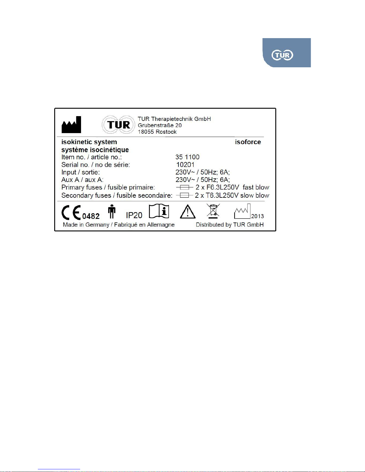
5.2.1 User Manual Isoforce
REV 5 01st July 2014 page 76 von 77
TUR Therapietechnik GmbH | Grubenstr. 20 | 18055 Rostock | Germany
8.1 Device Label
The label is located at the rear side of the electronic assembly.
Page 77
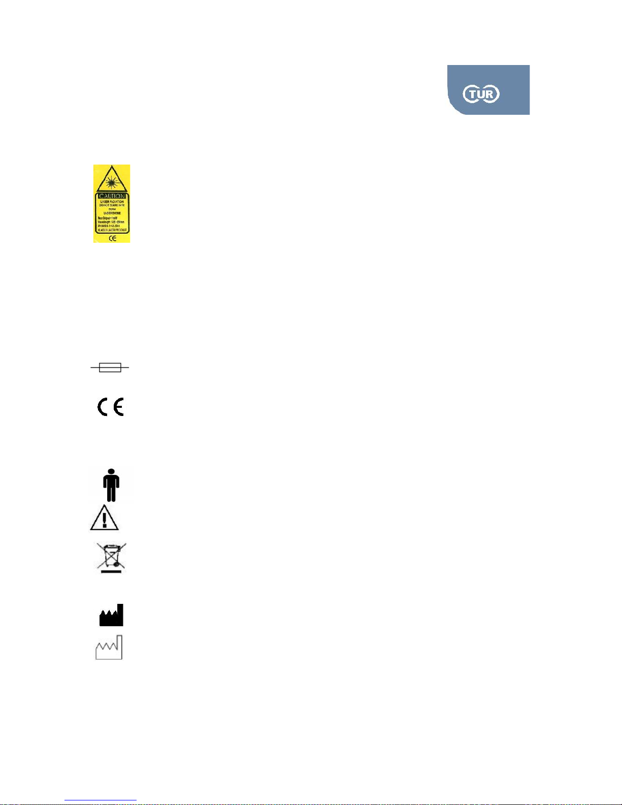
5.2.1 User Manual Isoforce
REV 5 01st July 2014 page 77 von 77
TUR Therapietechnik GmbH | Grubenstr. 20 | 18055 Rostock | Germany
8.2 Laser Labeling
8.3 Symbol Explanation
~
Alternating Current
Safety Fuses
This product conforms with the Directives for medical
products (93/42/EWG)
Conformity Assessment according to MDD/93/42/EEC/ in
cooperation with the notified body MedCert
Classification B
Accompanying documents
Disposal in accordance to the disposal directives for
electrical and electronic devices
IP
Protection degree against liquids and object insertion
Manufacturer
Production Date
0482
 Loading...