


Lifeline Smart Hub
TM
&
Device Management Platform


Lifeline Smart HubTM & Device Management Platform Contents
D5727050C Page 3 of 80
Contents
Contents ............................................................................................................. 3
Appendices ........................................................................................................ 5
1 Introduction ............................................................................................. 6
1.1 Document purpose ......................................................................................................................6
1.1.1 Versions .......................................................................................................................................................................6
1.2 Overview ......................................................................................................................................6
1.2.1 Smart Hub communication methods ...........................................................................................................................6
1.3 Typographical conventions ..........................................................................................................8
1.4 Related documents ......................................................................................................................8
2 What’s in the Smart Hub box.................................................................... 9
2.1 The Smart Hub .......................................................................................................................... 10
2.1.1 Front/top view ...........................................................................................................................................................10
2.1.2 Rear view ...................................................................................................................................................................10
2.1.3 Base view ...................................................................................................................................................................10
2.2 Warning/status lights on the Smart Hub .................................................................................. 11
2.3 Personal radio trigger ............................................................................................................... 13
3 Installing the Smart Hub ......................................................................... 14
3.1 Stage 1 – Determine the location of the Smart Hub ................................................................ 14
3.2 Stage 2 – Connect leads and power up the Smart Hub ............................................................ 15
3.2.1 Connect the optional Ethernet cable .........................................................................................................................15
3.2.2 Connect the mains power adaptor ............................................................................................................................15
3.3 Stage 3 – Check use of the internal antenna ............................................................................ 16
3.4 Stage 4 – Confirm the cellular signal strength .......................................................................... 16
3.5 Stage 5 – Set up the external cellular antenna......................................................................... 17
3.6 Stage 6 – Prepare sensors for use as the virtual property exit sensor ..................................... 18
3.7 Stage 7 – Register personal triggers/telecare sensors ............................................................. 18
3.8 Stage 7 – Test the range of personal triggers/telecare sensors ............................................... 19
3.9 Stage 8 – Connect hardwired devices ...................................................................................... 19
3.9.1 Connect a hardwired input device .............................................................................................................................20
3.9.2 Connect a hardwired output device ..........................................................................................................................20
3.10 Stage 9 – Fit the Smart Hub in the required location ............................................................... 21
3.10.1 External antenna........................................................................................................................................................21
3.10.2 Wall mounting with pattress .....................................................................................................................................22
3.10.3 Wall mounting without pattress ................................................................................................................................23
3.10.4 Fitting the table stand ................................................................................................................................................24

Lifeline Smart HubTM & Device Management Platform Contents
D5727050C Page 4 of 80
4 Configuring the Smart Hub ..................................................................... 26
4.1 Stage 1 – Log on to DMP and access the configuration settings .............................................. 27
4.2 Stage 2 – Configure the time zone ........................................................................................... 30
4.3 Stage 3 – Configure speech message settings .......................................................................... 31
4.4 Stage 4 – Configure pendant signalling during an alarm call ................................................... 32
4.5 Stage 5 – Configure IP data communications settings ............................................................. 33
4.6 Stage 6 – Configure monitoring centre settings ....................................................................... 34
4.7 Stage 7 – Register and configure personal triggers and telecare sensors ............................... 37
4.8 Stage 8 – Configure the virtual property exit sensor ............................................................... 40
4.9 Stage 9 – Configure ambient temperature monitoring ............................................................ 41
4.10 Stage 10 – Configure inactivity monitoring .............................................................................. 42
4.11 Stage 11 – Configure hardwired input...................................................................................... 43
4.12 Stage 12 – Configure Cancel At Source feature ........................................................................ 43
4.13 Stage 13 – Configure events ..................................................................................................... 46
4.14 Stage 14 – Configure event suppression .................................................................................. 48
4.15 Stage 15 – Configure the Home or Away feature ..................................................................... 49
4.16 Stage 16 – Configure periodic calls ........................................................................................... 50
4.17 Stage 17 – Configure power fault monitoring settings ............................................................ 54
4.18 Stage 18 – Configure line ringing settings ................................................................................ 55
4.19 Stage 19 – Configure DMP update announcements ................................................................ 55
4.20 Stage 20 – Save changes to DMP .............................................................................................. 56
5 Testing the installation ........................................................................... 58
5.1 Stage 1 – Test the range of personal triggers/telecare sensors registered using DMP ........... 58
5.2 Stage 2 – Test alarm calls ......................................................................................................... 58
5.3 Stage 3 – Test virtual property exit sensor ............................................................................... 59
5.4 Stage 4 – Test hardwired output .............................................................................................. 59
5.5 Stage 5 – Ready to use.............................................................................................................. 59

Lifeline Smart HubTM & Device Management Platform Appendices
D5727050C Page 5 of 80
Appendices
A Powering down the Smart Hub .............................................................. 60
B Smart Hub announcements .................................................................... 61
C Status of the Smart Hub ......................................................................... 65
D Applying a template to a device ............................................................. 67
E DMP online help ..................................................................................... 69
F List of supported triggers/sensors .......................................................... 70
G List of typical default Smart Hub event settings ..................................... 71
H Technical data ........................................................................................ 74
H.1 Battery information .................................................................................................................. 74
H.2 Technical details – Europe ........................................................................................................ 74
H.3 Technical details – Australia ..................................................................................................... 75
I Glossary .................................................................................................. 76
J Contact details ....................................................................................... 79

Lifeline Smart HubTM & Device Management Platform Introduction
D5727050C Page 6 of 80
1 Introduction
1.1 Document purpose
This document is intended to guide an installer through the process of installing and configuring the
Smart Hub ready for use. It is split into four main sections:
1. The Lifeline Smart Hub
TM
itself – including physical appearance, sockets and ports, standard radio
peripherals and indicators.
2. Step-by-step guide to physically installing the Smart Hub unit.
3. Step-by-step guide to configuring the Smart Hub using DMP.
4. Step-by-step guide to testing the Smart Hub once physically installed and configured.
It is assumed that the installer has familiarity with telecare alarm units and has received appropriate
training specific to the Smart Hub and DMP.
1.1.1 Versions
This document reflects DMP version 2.9.7 and Smart Hub firmware version 5.4.5 and related
configuration schema version 5.4.1.
1.2 Overview
The Lifeline Smart Hub is Tunstall’s latest home unit. Able to communicate using digital (IP) protocols
over cellular/mobile networks and fixed line broadband, it opens a new world of possibilities for the
provision of care in the home.
The Lifeline Smart Hub retains core functionality from Tunstall’s existing and past Lifeline products,
enabling users to access help 24 hours a day by pressing a button on the unit, or from elsewhere in
their home by using a radio pendant worn on the wrist or neck. The call is answered by specially
trained monitoring centre operators, who have the user’s information to hand and will respond
appropriately, e.g. contacting a family member or neighbour or calling the emergency services.
Tunstall’s new Device Management Platform (DMP) has been introduced to provide flexible cloudbased management of Smart Hub units, allowing their firmware and configuration settings to be
updated remotely. It is completely separate from the call handling platform, so plays no role in
telecare alarm handling nor does it hold records relating to Smart Hub users.
With digital (IP) connectivity and benefitting from Tunstall’s DMP, the Lifeline Smart Hub provides a
ground-breaking, future-proof foundation for the delivery of Connected Care.
1.2.1 Smart Hub communication methods
Monitoring centre and Smart Hub
A Smart Hub has three methods of connection to the monitoring centre, so that an alternative
method may be used if one or both of the others are unavailable. It can communicate:
1. Across a cellular data network to access the internet for communication of data
2. Using an Ethernet/fixed broadband line to access the internet for communication of data,
including Voice over Internet Protocol (VoIP)

Lifeline Smart HubTM & Device Management Platform Introduction
D5727050C Page 7 of 80
3. Across a cellular network for voiceband, that is, voice, ‘tones’ and also SMS communication
Communication over cellular connection paths (1 & 3) uses a network accessed by the SIM card. They
are used to transmit both data, such as alarm information, and voice calls between the Smart Hub
and monitoring centre. In some instances, path 3 can also be used to transmit the alarm call data in
the form of an SMS message. Typically, devices can ‘roam’ between networks thus maximising
coverage and availability. For data transmissions, this method of connection is similar to accessing
the internet on a smart phone (whilst not on a Wi-Fi) network and, for making a voiceband call,
making a mobile phone call.
An Ethernet/fixed broadband line (2) directly connects the internet to the device, via the user’s own
domestic or other local broadband router. This can be used to transmit both IP data, such as alarm
calls, and VoIP calls between the operator and the Smart Hub user. This method of connection is
similar to using any other device to access the internet via a fixed broadband line.
Domestic broadband connections can be unreliable, especially in the case of a mains power failure to
the router/modem. However, cellular services usually remain available, providing the device is within
the coverage area of an accessible network. Because of this, Tunstall recommends that you do not
rely solely on a domestic Ethernet/fixed broadband connection.
DMP and Smart Hub
A Smart Hub has two methods of accessing the internet for connection to DMP. It can communicate:
1. Across a cellular data network
2. Using an Ethernet/fixed broadband line
The connection is used to transmit data such as heartbeats, firmware and configuration updates
between DMP and the Smart Hub.

Lifeline Smart HubTM & Device Management Platform Introduction
D5727050C Page 8 of 80
1.3 Typographical conventions
• Names of fields, buttons, etc. are shown in bold.
• References, including those to external documents, are shown in italics.
• Links to other sections of the document are shown in teal.
• Notes are indicated by the ✍ icon.
• Warnings are indicated by the
⚠
icon and have rule lines both above and below their text.
1.4 Related documents
Part No.
Title
D5727002A
Lifeline Smart HubTM User Guide - Australia
D5727004A
Lifeline Smart HubTM Short Guide – Germany
D5727007A
Lifeline Smart HubTM User Guide – UK
D5727008A
Lifeline Smart HubTM User Guide – Europe-wide
D5727051B
Device Management Platform Reference Guide

Lifeline Smart HubTM & Device Management Platform What’s in the Smart Hub box
D5727050C Page 9 of 80
2 What’s in the Smart Hub box
Each Smart Hub box contains:
Smart Hub
Personal Radio Trigger
(type is region specific)
or
Together with:
• the personal radio trigger wearing options, that is, a wrist strap and a neck cord
• a mains power adaptor, along with a with a three metre cable
• a user guide, which should be left with the unit.
If any of the above is missing, please contact your supplier.
The Smart Hub comes with a pre-fitted SIM card, accessing the Tunstall Connectivity communication
service.
Optional Extras:
External Antenna (S2205017)
Pattress (D5702920)
Table Stand (D5702904)
Lifeline Smart HubTM & Device Management Platform What’s in the Smart Hub box
D5727050C Page 10 of 80
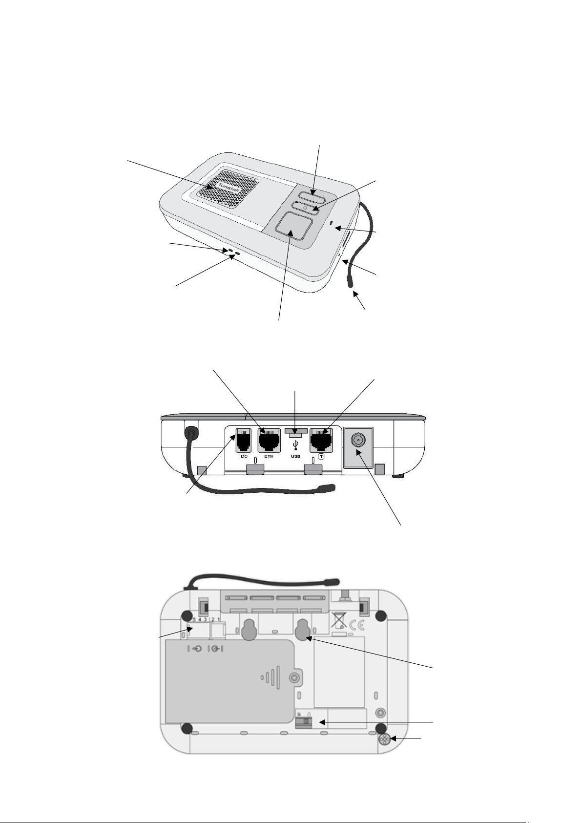
2.1 The Smart Hub
2.1.1 Front/top view
2.1.2 Rear view
2.1.3 Base view
Home/Away button (yellow)
Cancel button (green)
Status LED (red/green)
Microphone
Radio antenna
Ethernet connectivity LED
Cellular signal
strength LED
Speaker
Help button (red)
Ethernet port (yellow)
Connector for external cellular
antenna (optional extra)
DC socket for the power
supply unit
Micro USB port
(service use only)
Tunstall TAPIT port
(service use only)
Ringer on/off switch
Connection points for
wired input/output
Wall mounting key-slots
Ambient temperature
sensing port

Lifeline Smart HubTM & Device Management Platform What’s in the Smart Hub box
D5727050C Page 11 of 80
2.2 Warning/status lights on the Smart Hub
Home/Away button (yellow)
Smart Hub status
On
Away mode
Off
Home mode
Status LED (green/red)
Smart Hub status
Green LED on
Normal mode
Red LED flashing
(one every four seconds)
Low internal battery
Red LED flashing
(one every second)
No external communications
Red/Green LED alternate
Reduction in radio coverage
Yellow LED flashing
Configuration/software
update in progress
Help button(red)
Smart Hub status
On
Normal mode
Flashing
(one every four seconds)
Normal mode running on
battery
When operating on battery
power any other active
status indication will also
flash
Flashing
(one every second)
Alarm mode or
Programming mode
Flashing
(two every second)
Registration mode

Lifeline Smart HubTM & Device Management Platform What’s in the Smart Hub box
D5727050C Page 12 of 80
Cellular Network Signal Strength status
The indicated presence of a cellular signal
relates to the ability to connect to a network
and support a voice/tone connection. There
may be situations (usually temporary) when a
network connection exists but a data
connection is not available.
(Dark) Green
Strong signal
Yellow/Light – Green
Good signal
Orange – Red
Poor signal
White
No SIM or network
connection
Flashing White
Incorrect SIM PIN
Ethernet status
Green
Connected to the
router and has
internet access
Orange – Red
Connected to
powered router but
no internet access
available
Off
Not connected to the
router or router not
powered

Lifeline Smart HubTM & Device Management Platform What’s in the Smart Hub box
D5727050C Page 13 of 80
2.3 Personal radio trigger
TX4 Pendant
Wearing Options
Wrist Strap
Neck Cord
When pressed, the red LED on the pendant:
• lights up to indicate activation
• flashes to indicate that its battery is low
• turns green to indicate the Smart Hub has received the signal
from the pendant.
MyAmie Pendant
Wearing Options
Wrist Strap
Neck Cord
When pressed, the red LED on the pendant:
• lights up to indicate activation
• flashes to indicate that its battery is low.
LED
LED

Lifeline Smart HubTM & Device Management Platform Installing the Smart Hub
D5727050C Page 14 of 80
3 Installing the Smart Hub
Before installation, the Smart Hub must be prepared for active use, including:
• Within DMP:
• moving the device from virtual district “Customer Stock” into the appropriate active district
• defining some, if not most, aspects of the unit’s configuration, typically by the use of templates
• either downloading the defined configuration attributes from DMP to the unit and then
installing them, or ensuring they are ready to download and install when the unit powers up
and connects to DMP.
• At the destination monitoring centre system:
• setting up a record for the Smart Hub, typically including property and user details.
As you go through the installation, you may hear the Smart Hub make several announcements. For
an explanation of these, please refer to Appendix B, Smart Hub announcements.
General installation advice
Do:
• Follow the information contained in this guide
• Fully test the installation before leaving it operational
• Follow the shut-down process, if you need to disconnect and switch off a Smart Hub.
Do not:
• Expose the Smart Hub to water or other liquids
• Connect cables other than those stated in this guide.
3.1 Stage 1 – Determine the location of the Smart Hub
Locate the unit in an area that:
• provides good audio coverage for the user
• is not close to sources of heat, noise or electrical interference, such as televisions, radios, washing
machines, microwave ovens, personal computers etc.
• is within safe cable reach of a mains socket
• is likely to provide good cellular signal availability
• if required, is within safe cable reach of the user’s internet router.
The unit should be in the location and position in which it will remain when in operation. However, it
should not be permanently fixed at this point in the installation as it may need to be moved at a later
stage, for example, if cellular signal is insufficient.

Lifeline Smart HubTM & Device Management Platform Installing the Smart Hub
D5727050C Page 15 of 80
3.2 Stage 2 – Connect leads and power up the Smart Hub
3.2.1 Connect the optional Ethernet cable
This is required only if there is to be a fixed line broadband connection. To connect the optional
Ethernet cable:
1. Insert an Ethernet cable into the yellow port on the rear of the
Smart Hub labelled ‘ETH’. Use a good quality CAT5 or better cable of
a suitable length.
2. Connect the other end of the Ethernet cable to the user’s internet
router, ensuring it is safely routed so as not to present any hazards.
3.2.2 Connect the mains power adaptor
⚠
Only use the power adaptor supplied with the unit and ensure all preceding steps are
complete, including the Ethernet/fixed broadband service connections, as required.
To connect the mains power adaptor and power up:
1. Plug the mains adaptor into the Smart Hub socket labelled
‘DC’.
2. Connect the adaptor to the mains power.
The Smart Hub starts to power up, with the status LEDs on the
top and front of the Smart Hub changing to indicate progress. See Section 2.2, Warning/status lights
on the Smart Hub, for the indications on the Smart Hub relating to cellular and internet service. As
the unit powers up, it may make several announcements, as listed in Appendix B, Smart Hub
announcements.
On completion of power up, the unit attempts to connect to DMP. This may take a minute or two.
Once connected, the Smart Hub may download updated configurations or operating firmware, as
indicated by the announcements it makes. In addition, if the operating firmware is updated, the
Smart Hub may make alarm calls. These are memorised calls which previously failed to connect and
were not removed by pressing the green Cancel button.
3. If there is no Ethernet connection and the cellular signal strength is insufficient, connection is not
possible. In this case, check the possible communications channels:
• For the cellular service, check that the connection status that appears on the device’s Cellular
service tab within DMP is either “Activation Ready” or “Activated”, as described in the Device
Management Platform Reference Guide.
• For the broadband connection, check the cabling is correctly fitted, the router is working
correctly, the service is enabled.
Once connection has been established, then:
• If the Smart Hub is new and has not been previously installed, go to Stage 4 to confirm the cellular
signal strength. This is because it will be configured automatically to use its internal antenna.
• If the Smart Hub has been previously installed or you are unsure whether it is configured to use
the internal antenna, go on to the next stage to check use of this antenna.

Lifeline Smart HubTM & Device Management Platform Installing the Smart Hub
D5727050C Page 16 of 80
3.3 Stage 3 – Check use of the internal antenna
You implement the internal antenna as follows:
1. Press and hold the yellow Home/Away button for 10 seconds.
2. If the unit announces:
• "Internal antenna selected", the unit has switched to using the internal antenna
• "External antenna selected”, repeat step 1 to return to using the internal antenna
• "Please wait", the unit is unable to process the request immediately, for example, if an alarm
call is currently raised. Once the Smart Hub can process the request, it makes the appropriate
announcement which you action as required.
3. Once the unit is using the internal antenna, go on to the next to stage to confirm cellular signal
strength.
3.4 Stage 4 – Confirm the cellular signal strength
To confirm the cellular signal strength:
1. Ensure that the LED status indicator on the unit is normal, as described in Section 2.2,
Warning/status lights on the Smart Hub.
2. Ensure the red Help button is in normal mode, as described in Section 2.2, Warning/status lights
on the Smart Hub. If an alarm is in progress, i.e. the unit is in alarm mode, deal with the alarm
before continuing with the test.
3. Test the cellular signal strength, as follows:
a. Note the colour of the LED status indicator on the Smart Hub.
b. Press and hold the yellow Home/Away button for 6 seconds.
The Smart Hub announces the cellular signal strength as a value from 0 (No signal) to 31
(Strong signal) every ten seconds for a period of five minutes. To cancel these announcements,
press the green Cancel button.
4. Use the results of the tests to determine the overall cellular signal strength from the table below.
Smart Hub
Announcement
Smart Hub LED Colour
Overall Signal Strength
0
White
No signal – connection not made
1 to 6
Orange – Red
Poor signal – may not provide consistent service
7 to 9
Yellow – Light Green
Acceptable signal
10 to 18
Yellow – Light Green
Good signal
19 to 31
Dark Green
Strong signal
✍
Tunstall strongly recommend that you consider only ‘Acceptable’, ‘Good’ or ‘Strong’ cellular
signal strengths to be sufficient.

Lifeline Smart HubTM & Device Management Platform Installing the Smart Hub
D5727050C Page 17 of 80
5. If using the internal antenna and the cellular signal strength is insufficient:
a. Repeat this test in differing locations within the property. Ensure you allow sufficient time, at
least 30 seconds, for the LED status indicators to show the change in signal with each move.
Once you find a suitable location, no further cellular strength testing is required.
Tip: You may find it more convenient to disconnect the mains power/Ethernet cables from the
unit for these tests, reconnecting them at the end of this step. However, in this case the LED
status indicators will take up to two minutes to update.
b. If you cannot find a suitable location, complete stage 5 to set up the external antenna and
repeat this test to check changes to the cellular signal strength.
6. If using the external antenna and the cellular signal strength is insufficient:
a. Repeat this test with the antenna in differing locations within the property. This may require
you to move both the unit and antenna. Ensure you allow sufficient time, at least 30 seconds,
for the LED status indicators to show the change in signal with each move. Once you find a
suitable location, no further cellular signal strength testing is required.
Tip: You may find more convenient to disconnect the mains power/Ethernet cables from the
unit for these tests, reconnecting them at the end of this step. However, in this case the LED
status indicators will take up to two minutes to update.
b. If no suitable location can be found, contact your supervisor for further instructions.
Once you have a location with suitable cellular strength for the unit, then:
• If you have one or more personal triggers or telecare sensors to register, go to stage 6.
• If you have no additional triggers/sensors, go on to stage 7 to test the range of the personal
trigger supplied with the Smart Hub.
3.5 Stage 5 – Set up the external cellular antenna
Connecting an optional external cellular antenna (part number S2205017) will increase the unit’s
announcement values by two or three, with three representing more than double the original signal
strength. Note that the unit’s announcements do not increase proportionally to signal strength. In
addition, the antenna gives greater flexibility in locating an area with a good signal which in turn will
increase the signal further.
To connect the external cellular antenna:
1. Connect the antenna to the antenna socket on the rear of the
Smart Hub.
2. Temporarily fix the body of the antenna vertically. This should be:
• at least 0.5m from the Smart Hub
• on a non-metallic surface
• in an area expected to have a good signal, such as near a window
• indoors as the antenna is not waterproof.
Once connected, implement the external antenna as follows:
1. Press and hold the yellow Home/Away button for 10 seconds.
2. If the unit announces:

Lifeline Smart HubTM & Device Management Platform Installing the Smart Hub
D5727050C Page 18 of 80
• "External antenna selected", switching to using the external antenna is complete
• "Internal antenna selected”, repeat step 1 to return to using the external antenna
• "Please wait", the unit is unable to process the request immediately, for example, if an alarm
call is currently raised. Once the Smart Hub can process the request, it makes the appropriate
announcement which you action as required.
If the Smart Hub did not connect to DMP in a previous installation stage but can now make a
connection, the unit may download updated configurations or operating firmware, as described in
that stage.
3. Once connection has been established, return to Stage 4 to confirm cellular signal strength.
3.6 Stage 6 – Prepare sensors for use as the virtual property
exit sensor
Omit this stage if the client does not require a virtual property exit sensor.
To prepare the sensors required for use as the virtual property exit sensor:
1. Ensure that a Universal Sensor is installed on the required door(s) and is set to door open/door
close mode.
2. Ensure that one or more fast PIRs are installed to the side of each doorway to be monitored,
covering the approach to the door but not the final inch of the door closing action. (This avoids
false activity being detected after door closure, as the Universal Sensor registers closure when the
door is close to the door frame, not when it actually closes.)
3.7 Stage 7 – Register personal triggers/telecare sensors
Next, you locally register any personal trigger or telecare sensor with ‘plug and play’ functionality.
The only exception is the personal trigger supplied with the Smart Hub, as this is already registered.
To locally register the ‘plug and play’ triggers/sensors:
1. Press and hold down the green Cancel button as shown below.
2. When the Smart Hub bleeps (after approximately five seconds), release the green Cancel button.
The Smart Hub announces, ‘Programming mode’, and the red Help button flashes slowly.
3. Press and hold down the green Cancel button.
4. When the Smart Hub bleeps (after approximately three seconds), release the green Cancel
button. The Smart Hub announces, ‘Registration Mode,’ and the red Help button flashes rapidly.
5. Activate the trigger/sensor. The Smart Hub makes an announcement confirming the registration.

Lifeline Smart HubTM & Device Management Platform Installing the Smart Hub
D5727050C Page 19 of 80
6. Register any remaining triggers/sensors by repeating step 3 onwards. If you leave more than 2
minutes between registrations, repeat the process from step 1 as the Smart Hub will have
reverted to normal operating mode.
7. Press the green Cancel button to revert to normal operating mode.
8. Press the green Cancel button to initiate a DMP connection. Typically, within a few seconds
though it can take up to a minute or so, the unit announces:
• “Connected to DMP” if it can connect to DMP
• “Connection attempt to DMP failed” if it cannot connect to DMP
Once connected, the Smart Hub uploads the trigger/sensor details, as indicated by the
announcements it makes. Appendix B, Smart Hub announcements, provides details of the spoken
announcements which may be heard during this this step.
Once you have registered the triggers/sensors, go on to the next stage to test their range.
3.8 Stage 7 – Test the range of personal triggers/telecare
sensors
You need to test the range of the personal trigger supplied with the Smart Hub and any
trigger/sensor you registered in the previous stage.
To test the range of the triggers/sensors:
1. Press and hold down the green Cancel button.
2. When the Smart Hub bleeps (after approximately five seconds), release the green Cancel button.
The Smart Hub announces, ‘Programming mode’, and the red Help button flashes slowly.
3. Activate a trigger/sensor. The Smart Hub announces the trigger/sensor type and beeps to confirm
that it is within range. The announcement is at the highest possible volume, but you can adjust
this when configuring the unit as described in Section 4.3, Stage 3 – Configure speech message
settings.
4. If the trigger/sensor is portable, then to check coverage, repeat step 3 with the trigger/sensor at
different locations within the property.
5. Repeat steps 3 and 4 for each trigger/sensor. If you leave more than 2 minutes between tests,
repeat the process from step 1 as the Smart Hub will have reverted to normal operating mode. As
a warning, the unit emits “pip” tones towards the end of this 2 minute interval.
Once you have tested the range of the triggers/sensors, then:
• If you need to connect any hardwired devices, complete stage 8.
• If you need to fix the Smart Hub permanently in position, including its external antenna, or are
using a table stand, complete stage 9.
If neither stage is required then installation is complete, and you go on to configure the Smart Hub
unit, as described in Section 4, Configuring the Smart Hub.
3.9 Stage 8 – Connect hardwired devices
The steps required to connect input and output hardwired devices differ slightly, so are described
separately below.

Lifeline Smart HubTM & Device Management Platform Installing the Smart Hub
D5727050C Page 20 of 80
Once you have connected any required hardwired device, then:
• If you need to fix the Smart Hub permanently in position, including its external antenna, or are
using a table stand, complete stage 9.
If stage 9 is not required then installation is complete, and you go on to configure the Smart Hub unit
as described in Section 4, Configuring the Smart Hub.
3.9.1 Connect a hardwired input device
To connect a hardwired input device:
1. Check the trigger/sensor provides a voltage-free normally-open or normally-closed contact
output.
2. Locate the hardwired input connections on the underside of the unit within a green terminal
block, that is, positions 1 and 2.
3. Connect the pair of wires to positions 1 and 2 as follows:
a. Using a narrow-bladed screwdriver, depress the orange spring-clamp contact control lever.
b. Place the wire in position 1 or 2 of the block, as required.
c. Release the lever.
4. Secure the cable appropriately to protect against strain and accidental disconnection.
3.9.2 Connect a hardwired output device
To connect a hardwired output device:
1. Check the device is suitable for control by a voltage-free relay contact rated at 1A-30Vdc or
300mA-125Vac.
2. Locate the hardwired input connections on the underside of the unit within the green terminal
block, that is, positions 3, 4 and 5.
Connection cable
Adhesive strain relief tie
Spring-clamp contact
Input
Output

Lifeline Smart HubTM & Device Management Platform Installing the Smart Hub
D5727050C Page 21 of 80
3. Connect the pair of wires to positions 3 and 4, if the contacts are normally open, and positions 4
and 5, if normally closed, as follows:
a. Using a narrow-bladed screwdriver, depress the orange spring-clamp contact control lever.
b. Place the wire in position 3, 4 or 5 of the block, as required.
c. Release the lever.
4. Secure the cable appropriately to protect against strain and accidental disconnection.
3.10 Stage 9 – Fit the Smart Hub in the required location
This section describes how to fit the Smart Hub if it:
• requires an external antenna, or,
• is to be mounted on a wall, or,
• uses the table stand.
If the Smart Hub is to be wall mounted, you can either use the optional Tunstall pattress or fit the
unit directly to a wall using the key-slots moulded into the rear of the case. If the Smart Hub is to be
placed on a horizontal surface, you can fit it with the optional Tunstall table stand which tilts the unit
at an angle and allows for tidy cabling.
✍
Before fitting the Smart Hub in the required location, ensure you take note of its product
code (PRC) as it will be inaccessible once the unit is fitted. You use the product code (PRC)
to identify the unit when configuring it within DMP.
Once you have permanently fitted the Smart Hub, you go on to configure the Smart Hub unit, as
described in Section 4, Configuring the Smart Hub.
3.10.1 External antenna
Fix the antenna permanently using its self-adhesive strip.
Input
Output
Normal condition

Lifeline Smart HubTM & Device Management Platform Installing the Smart Hub
D5727050C Page 22 of 80
3.10.2 Wall mounting with pattress
Tunstall is able to supply an optional pattress (part number D5702920) which conceals the cable
connections to the unit and allows the unit to be mounted directly to the wall, or onto a recessed
electrical back-box. If a unit with an Ethernet connection is to be wall mounted with the pattress,
then, prior to installation, ensure that the Ethernet cable and connector fit under the cover.
⚠
Use with metal back-boxes is not recommended due to potential radio frequency
shielding effects.
To mount the Smart Hub on a wall using the pattress:
1. Disconnect the cables from the Smart Hub. Place the pattress in the correct horizontal position on
the wall. If the connecting cables are concealed in the wall, feed them through the larger central
hole. See image 1.
2. Use the screw holes/slots to fix the pattress to the wall, choosing appropriate fixings for the type
of wall. The holes/slots enable fitting to standard electrical back-boxes.
3. Remove the two rubber feet from both front/lower corners of the Smart Hub (image 2a) and
store them in the slots provided in the pattress (image 2b).
4. Re-connect the cables to the unit, as described in previous stages.

Lifeline Smart HubTM & Device Management Platform Installing the Smart Hub
D5727050C Page 23 of 80
5. Clip the Smart Hub onto the wall pattress, ensuring any cables correctly feed through the pattress
back or slot, as required. Images 3a and 3b show how to locate and clip the Smart Hub to the
pattress, but for clarity show the unit without either the cabling or the wall.
3.10.3 Wall mounting without pattress
To mount the Smart Hub on a wall without using a pattress:
1. Place the unit in the correct horizontal position on the wall and use the two wall mount markers
to accurately mark the wall, as shown below. Note that the diagram is not drawn to scale so
should not be used for measuring purposes.
2. Drill 2 holes 40 mm apart, that is, on the marks you made in the previous step.
3. Firmly attach suitable screws for the type of wall, leaving the screw heads protruding from the
surface.
4. Place the wall mounting points on the back of Smart Hub over the screws. Lower the unit to lock
the screw heads into the key-hole slots.
5. Check that the unit is held securely. If necessary, remove, adjust the screw length and repeat
step 4.

Lifeline Smart HubTM & Device Management Platform Installing the Smart Hub
D5727050C Page 24 of 80
3.10.4 Fitting the table stand
Tunstall is able to provide an optional table stand (part number D5702904) which allows the buttons
and speaker to be angled towards the user instead of lying flat on a surface. This also covers where
cables connect to the unit, which can help to prevent cables from being unplugged.
The stand is formed from two parts, a wall pattress (2) and an additional clip-on foot (3), and
requires the removal of the rubber feet (1).
To fit the table stand:
1. Remove the two rubber feet from both front/lower corners of the Smart Hub (image 1a). These
can be stored in the slots provided in the pattress (image 1b).
2. Clip the foot to the wall pattress, ensuring the foot is angled down. See image 2 and image 5.
2

Lifeline Smart HubTM & Device Management Platform Installing the Smart Hub
D5727050C Page 25 of 80
3. Feed the cables through the base of the foot and the large hole in the pattress. See image 3.
Connect the cables to the Smart Hub’s sockets.
4. Fit the table stand assembly to the Smart Hub whilst adjusting cables and feeding them
back/down as necessary. Image 4 shows how to locate and clip the assembly to the Smart Hub
but for clarity shows it without the cabling/foot.
5. Ensure that the completed assembly sits with the foot flat on a surface as shown in image 5 (with
cables passing out of the foot).
4
3
5

Lifeline Smart HubTM & Device Management Platform Configuring the Smart Hub
D5727050C Page 26 of 80
4 Configuring the Smart Hub
This chapter describes how to configure the Smart Hub unit using DMP.
To configure the Smart Hub unit installed in the previous chapter, you require:
• DMP username and password, with “Customer Advanced” permission level access to the
appropriate DMP district
• The device to be located in the required DMP district
• The list of configuration attributes to be amended, together with their required values, typically
provided by your supervisor. These values should be in line with your organisation’s policies, and,
if relevant, their customer’s policies. The only attributes that you should change without such
values are those relating to the user’s personal requirements.
• If your organisation enforces two-factor verification, you also require the tokens from Google
Authenticator and need to apply them at appropriate points in the configuration process. For
clarity, the procedure described in this chapter does not include any references to two-factor
verification. For details of this feature, refer to the Device Management Platform Reference Guide.
Tunstall strongly recommends that as much as possible of the configuration is carried out prior to
installation, but it is not possible to finalise all of it. As a minimum you need to change those settings
that relate to the user’s personal requirements, such as the ringing volume of the unit.
This chapter covers each setting that might require configuration in a typical installation. Please go
through all the stages of this chapter in the order they are presented, omitting those relating to the
settings that are pre-configured for the Smart Hub you are currently installing. The configuration
process is split as follows:
• Stages 1 to 5 relate to configuring the Smart Hub so that it can work in the appropriate time zone,
connect to communication channels, work with DMP, and make announcements in the
appropriate language.
• Stages 6 to 17 relate to the telecare and alarm operational features necessary for the Smart Hub
to operate in accordance with the service provider’s policies and the user’s requirements.
✍
For detailed descriptions of the DMP screens, the significance of the fields within them and
how their settings impact the Smart Hub, refer to the Device Management Platform
Reference Guide.
As you make changes to the unit’s configuration, DMP outlines each updated field in red.
These changes transfer from DMP to the Smart Hub whenever the Smart Hub next connects to DMP,
either at the regular interval (“heartbeat”) or when prompted by pressing the green Cancel button.
As an alternative to manually specifying all the settings, you may configure some of them by the
applying a template if this has not been done prior to installation. For details on how to do this, refer
to Appendix D, Applying a template to a device.

Lifeline Smart HubTM & Device Management Platform Configuring the Smart Hub
D5727050C Page 27 of 80
4.1 Stage 1 – Log on to DMP and access the configuration
settings
To log on to DMP and access the configuration settings:
1. Use a recent version of an internet browser such as Edge, Internet Explorer, Safari or Firefox, but
preferably Chrome, to access DMP’s web address. DMP is located at:
• Australia: https://dmp-au.tunstall.com
• China: https://dmp-cn.tunstall.com
• Europe: https://dmp-eu.tunstall.com
2. Enter your user name and password to display your Start page, which is similar to the following:

Lifeline Smart HubTM & Device Management Platform Configuring the Smart Hub
D5727050C Page 28 of 80
3. Select the Devices menu option, to display the View Devices List page.
4. If you have access to multiple customers and/or districts, select the customer and district
containing the device to be configured using the Customer and/or District drop-down lists.
5. Use any of the standard list options to display the Smart Hub’s details. Alternatively, click Show
advanced filter and then enter all or part of the 27-digit product code (PRC). Ensure that there is a
complete match between the product code listed on the Smart Hub’s label and the contents of
DMP’s SERIAL NUMBER field.
6. Select the Smart Hub by clicking on any of its details. DMP displays the Device Information
window, as shown below:

Lifeline Smart HubTM & Device Management Platform Configuring the Smart Hub
D5727050C Page 29 of 80
7. Click the SETTINGS button to open the Device Settings page. This selects the Ringing menu option
by default.
Lifeline Smart HubTM & Device Management Platform Configuring the Smart Hub
D5727050C Page 30 of 80
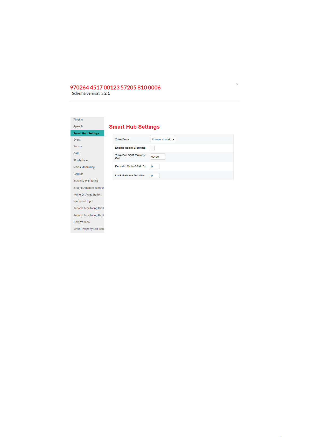
4.2 Stage 2 – Configure the time zone
To configure the time zone:
1. Within the Device Settings menu, select the Smart Hub Settings menu option to display:
If required, select the correct zone from the Time Zone drop-down list. If a change is made, the field
is outlined in red and DMP changes the SAVE button from grey to blue to indicate the pending
unsaved changes.
2. Leave the other settings in this group at their default values at this stage.

Lifeline Smart HubTM & Device Management Platform Configuring the Smart Hub
D5727050C Page 31 of 80
4.3 Stage 3 – Configure speech message settings
To configure the speech message settings:
3. Within the Device Settings menu, select the Speech menu option to display:
4. Select the appropriate language from the Language drop-down list.
5. If necessary, after discussion with the user, change the value of the Default Speaker Volume field
which defines the volume of the unit’s announcements but not the volume of the monitoring
centre operator’s voice. The user should have heard some announcements during the previous
stages of installation.
6. If announcements other than alarms are to be suppressed for part of each day, typically the user’s
sleeping hours:
a. Specify the start and end of this time period in the No Fault Monitoring Start Time and End
Time fields.
b. Ensure Disable Fault Monitoring Speech Within Time Window is ticked.

Lifeline Smart HubTM & Device Management Platform Configuring the Smart Hub
D5727050C Page 32 of 80
4.4 Stage 4 – Configure pendant signalling during an alarm
call
This section describes how to indicate whether a client’s pendant can be used to communicate with
the responding operator after they have raised an alarm using that pendant. This communication
takes the form of audio beeps generated by pressing the pendant.
To configure use of the pendant trigger’s audio beeps in this way:
1. Within the Device Settings menu, select the Calls menu option to display:
2. Ensure Personal Trigger Signal Beep in Active Call is ticked if the pendant may be used to
communicate with the responding operator whenever that pendant triggers an alarm; otherwise
ensure the field is clear.

Lifeline Smart HubTM & Device Management Platform Configuring the Smart Hub
D5727050C Page 33 of 80
4.5 Stage 5 – Configure IP data communications settings
This section describes how to configure the settings that define IP data communications between the
Smart Hub and DMP. Communication may take place using either a fixed-line broadband (Ethernet
Interface) or cellular/mobile networks (Cellular IP Interface); the former via a connection to the
user’s home broadband and the latter using the device’s cellular connection.
To configure the IP data communications:
1. Within the Device Settings menu, select the IP Interface menu option to display:
2. If both IP data communication methods are to be used, select the preferred method when both
available, from the Primary Communication Interface drop-down list. Typically, this is “Ethernet”.
⚠
It is strongly advised that the Smart Hub is not installed to use only an Ethernet
connection as this is usually unavailable during power failures to the user’s internet router.
3. Use the two checkboxes to indicate whether the unit is to make an announcement when the
Ethernet or cellular data connection fails or is restored.

Lifeline Smart HubTM & Device Management Platform Configuring the Smart Hub
D5727050C Page 34 of 80
4.6 Stage 6 – Configure monitoring centre settings
This section describes how to configure the settings related to calls made to the monitoring centre.
Typically, the configuration of settings relating to monitoring centre call sequences and destinations
will have already been applied, so it is unlikely that you need to go through this stage. However, if
you do have to enter or make changes to these settings, please ensure you:
• Have a list of call sequences and associated information. This must be in accordance with your
operating procedures and typically provided by your supervisor.
• Know which attributes require specifying/updating, the sequences or destinations to which they
relate and the values to which they will be set.
If you require an explanation of how sequences and destinations operate to enable calls to be made
correctly to the monitoring centre, refer to the Device Management Platform Reference Guide.
1. Within the Device Settings menu, select the Calls menu option to display:

Lifeline Smart HubTM & Device Management Platform Configuring the Smart Hub
D5727050C Page 35 of 80
2. For each destination you need to specify or update:
a. Select the relevant destination, by clicking the appropriate bar containing Destination. DMP
displays the related settings.
b. If not already specified, enter the Unit ID by which the Smart Hub being installed is known at
the monitoring centre destination being configured.
c. Ensure the Telephone Or IP Call drop-down list is set to:
• “IP Call”, if the destination being configured uses an IP protocol

Lifeline Smart HubTM & Device Management Platform Configuring the Smart Hub
D5727050C Page 36 of 80
• “Telephone Call”, if the destination uses a tone-based signalling protocol
• “SMS” if the destination uses Tunstall SMS protocol.
d. In the case of an IP destination, update the required attributes as follows:
i. Enter the destination monitoring centre’s address either as a numeric IP or a URL, for
example, “123.456.789.012” or “example.domain.com”.
ii. Select the IP alarm protocol used by the destination monitoring centre, either IPACS or
SCAIP.
iii. If required, make changes to the ARC Port, SIP Username, SIP Connection Method, SIP
Password, SIP Realm and Enable SIP Authentication fields. This should have been advised
by Tunstall after discussion with related parties.
iv. Select the IP connection path to be used for the alarm call, from the Connection Type drop-
down field, that is either “Ethernet” or “Cellular IP”.
v. Select “VoIP Call” or “GSM Call” from the Call Method drop-down list, depending on the
monitoring centre and chosen IP protocol. This defines how voice is to be transmitted
during the alarm call.
✍
If the chosen IP connection path is “Cellular IP”, the voice connection should be a GSM call,
as cellular data services may not support stable and reliable VoIP connections. Only use
VoIP if advised by Tunstall.
vi. For GSM calls using the IPACS protocol only, select either “Callback” or “Dial out” from the
IPACS GSM Call Back Method drop-down list. These options define whether the voice call is
to originate from the monitoring centre or Smart Hub respectively.
e. In the case of a telephone or SMS destination, update the required attributes as follows:
i. Enter the destination monitoring centre’s call or SMS receiving telephone number in the
Telephone Number field using ‘international’ format, for example, “+44…” or “0044…”.
3. If one of the destinations has its Telephone OR IP Call drop-down list set to “Telephone Call”, set
Signalling Mode to:
• “STMF Only” if the monitoring centre supports STMF signalling, as this mode is more resilient
over cellular voice band connections
• “DTMF”, if the monitoring centre uses BS8521 only
• “Last Successful”, if some monitoring centre equipment supports STMF and some does not.
This allows the Smart Hub to switch signalling modes when necessary. However, exhausting
initial attempts and switching modes may cause noticeable connection delays, therefore you
should only use this option when the destination is the last resort should all other
communication attempts fail.
4. For each call sequence you need to specify or update:
a. Select the call sequence to be specified or updated, by clicking the appropriate bar within the
Call Sequence area. DMP displays the related settings.

Lifeline Smart HubTM & Device Management Platform Configuring the Smart Hub
D5727050C Page 37 of 80
b. If the call sequence is to repeat from the beginning whenever it fails to connect to its
destination monitoring centre, ensure the Repeat Call Sequence On Completion checkbox is
ticked. Ensure it is clear if the sequence is not to repeat.
✍
Tunstall recommend that this option is enabled. However, in some cases this may not be
possible as this option must conform to national regulations. For example, some countries
have regulations preventing automatic telephone connection attempts from repeating an
unlimited number of times.
c. For each call sequence record:
i. Specify the number of attempts to be made to connect to the record’s destination, before
moving to the next call sequence record.
ii. Select the destination to be used at this point in the sequence from the Destination Index
drop-down list.
4.7 Stage 7 – Register and configure personal triggers and
telecare sensors
This section describes how to register and configure triggers/sensors so they prompt the Smart Hub
to take appropriate action, including raising alarms to a monitoring centre.
The pendant radio trigger provided with the Smart Hub comes pre-registered, so this stage is not
required if this is the only trigger/sensor.
1. Within the Device Settings menu, select the Sensor menu option. This displays the
triggers/sensors currently registered to the unit, either before installation or as part of the
installation process described in Section 3.6, Stage 6 – Prepare sensors for use as the virtual
property exit sensor.

Lifeline Smart HubTM & Device Management Platform Configuring the Smart Hub
D5727050C Page 38 of 80
2. For each trigger/sensor listed:
a. Click within the grey bar of the sensor line. DMP displays the selected trigger/sensor’s details.
This may include additional fields to the ones shown below.

Lifeline Smart HubTM & Device Management Platform Configuring the Smart Hub
D5727050C Page 39 of 80
b. Check that the details are correct.
c. If required, use the Sensor Location drop-down list to distinguish the trigger/sensor from
others of the same type. This can be by location, owner, or appliance/door type. This helps
operators to provide the best response to an alarm.
d. If the Sensor Type is “Door Contact” or “Passive Infrared (PIR)” and the sensor is to be used as
part of the virtual property exit sensor, ensure Enable Virtual Sensor is ticked. At least one
“Door Contact” and at least one “Passive Infrared (PIR)” must be defined as part of the virtual
property exit sensor.
e. If a trigger/sensor was added in error during the pre-installation preparation:
i. Click the button at the end of the trigger/sensor’s entry. DMP displays a confirmation
message:
ii. Click DELETE SENSOR to delete the trigger/sensor details from the list.

Lifeline Smart HubTM & Device Management Platform Configuring the Smart Hub
D5727050C Page 40 of 80
⚠
Only delete a trigger/sensor after confirming that the identifier on the DMP record
matches that on the trigger/sensor’s label. Always check afterwards that the correct
trigger/sensor has been deleted.
3. If you have any additional triggers/sensors to be registered , then for each trigger/sensor:
a. Press the ADD SENSOR button.
b. Enter the six-digit identification number of the new sensor/trigger in the Sensor ID.
c. Select its type from the Sensor Type drop-down list.
d. If required, uniquely identify the trigger/sensor by selecting a value from the Sensor Location
drop-down list.
e. If required, select its Enable Virtual Sensor checkbox.
4.8 Stage 8 – Configure the virtual property exit sensor
This section describes how to configure the virtual property exit sensor so that it correctly triggers
the Smart Hub to take appropriate action, including raising an alarm to the monitoring centre. This
feature requires appropriate door and PIR sensors to be correctly configured.
To configure the settings that relate to the virtual property exit sensor:
1. Within the Device Settings menu, select the Virtual Property Exit Sensor menu option.
2. Use the Enable Virtual Property Exit Sensor checkbox to enable/disable this feature as required.

Lifeline Smart HubTM & Device Management Platform Configuring the Smart Hub
D5727050C Page 41 of 80
3. Enter the time period in minutes for which a unit will monitor for a return to the property after
detecting an exit, in Absence Period. If the unit has not detected any return by the end of this
time period, it raises a ‘PES Client Wandered’ event.
4. For each day of the week, specify when the virtual property exit sensor is to be active by either:
• ensuring Enable 24 Hour Monitoring is ticked, or,
• specifying the Start Time and End Time of the monitoring period
If Enable 24 Hour Monitoring is ticked, the unit ignores the values of the Start Time and End Time
fields. If you specify a monitoring period where the End Time is less than the Start Time, then the
end time occurs during the following day, for example from 11:00pm to 7:00am.
5. Take note of whether the virtual sensor is currently active and, if not, tick the appropriate Enable
24 Hour Monitoring checkbox so that the virtual sensor can be tested.
4.9 Stage 9 – Configure ambient temperature monitoring
✍
After first power-up, there is a stabilisation period where the Smart Hub does not monitor
the ambient temperature. This normally lasts for 90 minutes. This is to prevent the unit
from generating an alarm if the Smart Hub has been stored in a hot or cold environment
prior to installation and has not yet stabilised.
To configure the settings that relate to the ambient temperature monitoring:
1. Within the Device Settings menu, select the Integral Ambient Temperature Monitoring menu
option to display:

Lifeline Smart HubTM & Device Management Platform Configuring the Smart Hub
D5727050C Page 42 of 80
2. Use the Enable Temperature Monitoring checkbox to enable/disable this feature, as required.
3. If monitoring is to be restricted to day-time only, ensure the Suppress Temperature Monitoring
At Night checkbox is ticked; otherwise ensure it is clear.
4. Set the low and high temperature thresholds appropriate for the user and local policies.
4.10 Stage 10 – Configure inactivity monitoring
To configure the settings that relate to inactivity monitoring:
1. Within the Device Settings menu, select the Inactivity Monitoring menu option to display:
2. To enable inactivity monitoring, ensure that the Inactivity Type drop-down list is set to “Inactivity
Simple” and that the Enable Basic Inactivity Monitoring checkbox is ticked. To disable it, set up
these attributes with any other values.
3. If inactivity monitoring is enabled, select the length of inactivity that causes an inactivity warning
period to start, that is, either 12 or 24 hours, from the Inactivity Period drop-down list.
4. If inactivity monitoring is enabled, select the length of the inactivity warning period, in minutes,
from the Inactivity Warning Period drop-down list.
Lifeline Smart HubTM & Device Management Platform Configuring the Smart Hub
D5727050C Page 43 of 80
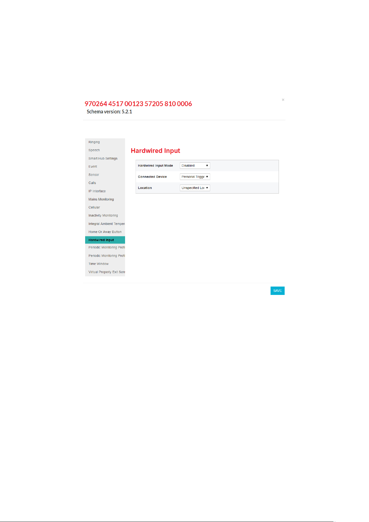
4.11 Stage 11 – Configure hardwired input
To configure any hardwired input:
1. Within the Device Settings menu, select the Hardwired Input menu option to display:
2. Select the normal state of the input, either, “Normally Open” or “Normally Closed”, from the
Hardwired Input Mode drop-down list.
3. Use Connected Device to specify the type of the hardwired trigger/sensor.
4. If required, use the Location drop-down list to distinguish the trigger/sensor from others of the
same type. This could be by location, owner, or appliance/door type.
4.12 Stage 12 – Configure Cancel At Source feature
Cancel At Source is a feature which allows an alarm to be repeated at a set interval until a full
cancellation action is taken physically at the Smart Hub unit. This can be used to ensure high
dependency clients are visited by a carer prior to an alarm being fully closed down.
Alarms are raised to the monitoring centre and the calls cleared by the operator in the usual manner.
If the configured alarm is not cancelled locally at the Smart Hub, then repeat calls to the monitoring
centre will automatically be made.
Whilst an alarm is pending local cancellation, the yellow Home/Away button surround will flash
slowly. Upon arrival, a carer then presses the green Cancel button to fully cancel the alarm, thus
preventing repeat calls.

Lifeline Smart HubTM & Device Management Platform Configuring the Smart Hub
D5727050C Page 44 of 80
To use the Cancel At Source feature:
1. Within the Device Settings menu, select the Cancel At Source menu option to display:
2. Set the interval between alarm repeats to the desired number of minutes. This would normally be
set in accordance with local policy, taking into account the dependency level of the client and the
likely time it will take for a carer to attend.
3. Select the Raise Carer Arrived On Cancel checkbox if a ‘Carer Arrived’ event is to be generated
upon the alarm being cancelled at the Smart Hub unit. This feature can be used to confirm the
cancellation by raising a ‘Carer Arrived’ notification to the monitoring centre.
4. If required, select the maximum number of repeat calls which can be made for each alarm. Value
0 indicates that there is no limit and repeat calls will be made until manual cancellation occurs.
5. For the types of alarm that should be handled with a Cancel At Source response, select each type
in the Event menu and set the Alarm Mode entry to ‘Cancel At Source’:

Lifeline Smart HubTM & Device Management Platform Configuring the Smart Hub
D5727050C Page 45 of 80
✍
In the event of multiple alarms being raised concurrently, only the original will generate
Cancel At Source repeats until it is manually cancelled. The concurrent alarms will still be
raised and need to be closed down by the monitoring centre.
As detailed in section 4.14, it is possible to configure time windows during which specified events will
not be raised as alarms by the Smart Hub unit. Where a sensor that has been configured for a Cancel
At Source response is triggered, and repeat alarms fall during the blocking period, the time window
settings will take precedence over the Cancel At Source settings and alarm repeats will be paused
until the blocking period has elapsed.
✍
Limitations: To avoid undesirable results, it is recommended that Cancel At Source mode is
only used with radio trigger, red Help button, inactivity, virtual property exit sensor and
hardwired input events. It should not be used for ‘technical’ alarms, such as those reporting
sensor low batteries, auto presence or mains power failures, for example.

Lifeline Smart HubTM & Device Management Platform Configuring the Smart Hub
D5727050C Page 46 of 80
4.13 Stage 13 – Configure events
For a list of the events and the typical default settings of their attributes, refer to Appendix G, List of
typical default Smart Hub event settings. However, Tunstall may deliver Smart Hubs with different
defaults according to local requirements, or your organisation may automatically apply a template on
receipt of each device which updates this configuration.
To configure events:
1. Within the Device Settings menu, select the Event menu option to display:

Lifeline Smart HubTM & Device Management Platform Configuring the Smart Hub
D5727050C Page 47 of 80
2. Select the event to be updated to display its configuration settings. Each event has the same set
of attributes, as shown below:
3. Update the drop-down lists and checkboxes, as required. The most common changes you may
need to make are:
• Setting Relay Behaviour of the hardwired output event to suit installation specific
circumstances
• Setting Audible Reassurance to either enabled or disabled to suit the installation and user’s
circumstances
• Changing the Call Sequence Index where there are multiple call sequences used by your
organisation
• Changing Alarm Mode to ‘Cancel At Source’ if this type of response is appropriate (see section
4.12).
4. Repeat steps 2 and 3 for each event that requires amendment.

Lifeline Smart HubTM & Device Management Platform Configuring the Smart Hub
D5727050C Page 48 of 80
4.14 Stage 14 – Configure event suppression
You can configure the Smart Hub to block a type of event that occurs within a specific time window
so that alarms relating to the event are not raised during that period. The types of event that can be
blocked are:
• TES Low Temp
• Door Usage Opening
• Door Usage Closing
• Pressure Mat Activation
• Enuresis Activation.
To define the alarms and time periods during which blocking occurs:
1. Within the Device Settings menu, select the Time Window menu option to display:
2. For each combination of event and time period during which the event is to be blocked:
a. Specify the Event Suppression Start Time and Event Suppression End Time of the blocked
period. If you enter an Event Suppression End Time that is less than the Event Suppression
Start Time, then the end time occurs during the following day, for example from 11:00pm to
7.:00am.
b. Select the type of event that is to be blocked from the Event Type drop-down list.
c. Select Enabled to implement the blocking.

Lifeline Smart HubTM & Device Management Platform Configuring the Smart Hub
D5727050C Page 49 of 80
4.15 Stage 15 – Configure the Home or Away feature
To configure the settings that relate to the Home or Away feature:
1. Within the Device Settings menu, select the Home Or Away Button menu option to display:
2. Update the Button Function checkbox to indicate whether the Home and Away feature is
implemented.
3. If required:
a. Specify the time delay in seconds between switching between Home and Away modes after
the yellow Home/Away button has been pressed.
b. Specify whether reminders to return to Home mode are to be played whenever the unit is in
Away mode and detects activity in the property.

Lifeline Smart HubTM & Device Management Platform Configuring the Smart Hub
D5727050C Page 50 of 80
4.16 Stage 16 – Configure periodic calls
✍
Fields relating to periodic calls should not be changed without discussion with your
supplier.
To configure the settings that relate to periodic calls:
1. If periodic calls are to be made using IP protocols:
a. Within the Device Settings menu, select the Periodic Monitoring Profile On Mains menu
option to display:
b. If required, set the interval in minutes for IP periodic calls whilst the unit is on mains power.
This should only be done after discussion with your supplier.

Lifeline Smart HubTM & Device Management Platform Configuring the Smart Hub
D5727050C Page 51 of 80
c. Select the Periodic Monitoring Profile On Battery menu option to display:
d. If required, set the interval in minutes for IP periodic calls whilst the unit is on battery. This
should only be done after discussion with your supplier.

Lifeline Smart HubTM & Device Management Platform Configuring the Smart Hub
D5727050C Page 52 of 80
2. If the periodic calls are to be made using GSM telephony (tone protocols):
a. Within the Device Settings menu , select the Smart Hub Settings menu option to display:
b. Set Periodic Calls GSM to the number of days’ interval between the test calls. If no calls are
required, set Periodic Calls GSM to zero.
3. Within the Device Settings menu, select the Calls menu option.
4. Either check that the required call sequence(s) are available or create new call sequence(s) to be
used for periodic calls, as described in Section 4.6, Stage 6 – Configure monitoring centre setting.
By convention, call sequence indexes 9 and 10 are used for periodic calls.
⚠
‘Telephone’ destinations (GSM/tone protocol destinations) should not appear in the
call sequence used by IP protocol periodic calls. Similarly, IP call destinations should not
appear in the call sequence used by telephone periodic calls.

Lifeline Smart HubTM & Device Management Platform Configuring the Smart Hub
D5727050C Page 53 of 80
5. Within the Device Settings menu, select the Event menu option and open the Periodic Call (IP)
Event or the Periodic Call (GSM) Event, as appropriate. DMP displays the same fields for each
event. The Periodic Call (IP) Event is shown below to illustrate the fields.
6. Select the required Call Sequence Index. By convention, organisations use call sequence indexes 9
and 10 for periodic calls.
7. Ensure Raise Alarm in Away Mode and Raise Alarm in Home Mode are ticked.
8. If the unit is to make periodic calls for both IP and GSM protocols, repeat steps 5 to 7 for the
other periodic call event.

Lifeline Smart HubTM & Device Management Platform Configuring the Smart Hub
D5727050C Page 54 of 80
4.17 Stage 17 – Configure power fault monitoring settings
To configure the power fault monitoring settings:
1. Within the Device Settings menu, select the Mains Monitoring menu option to display:
2. Ensure the Allow Immediate Mains Fail Alarm checkbox is clear, unless the monitoring centre is
to be immediately advised of mains power failure.
✍
Tunstall recommend you enable this option only for selected, high-risk clients; otherwise,
an area outage may result in the monitoring centre ‘flooding’ with simultaneous calls from
devices in the area.
3. If required by the user and if under your organisational policies, select the Enable Mains Failure
And Restoration Audible Warning checkbox so that the unit announces any mains failure and
subsequent restoration. All other fields are uneditable.

Lifeline Smart HubTM & Device Management Platform Configuring the Smart Hub
D5727050C Page 55 of 80
4.18 Stage 18 – Configure line ringing settings
To configure the line ringing settings that relate to the calls made to the unit by the monitoring
centre or other telecare-related source:
1. Within the Device Settings menu, select the Ringing menu option to display:
2. Ensure Enable Audible Ringing is ticked.
3. Select appropriate values for the remaining fields after discussion with the user of the unit.
4.19 Stage 19 – Configure DMP update announcements
To suppress announcements during update of the unit’s firmware or configuration settings:
1. Within the Device Settings menu, select the DMP menu option to display:

Lifeline Smart HubTM & Device Management Platform Configuring the Smart Hub
D5727050C Page 56 of 80
2. Ensure the Enable Audible Announcement For Software Download and Installation checkbox is
clear.
4.20 Stage 20 – Save changes to DMP
Once you have completed defining the Smart Hub’s configuration, you then go on to save these
changes in the Smart Hub’s DMP record and communicate them to the unit. To do this:
1. Within the Device Settings window, click the SAVE button.
DMP presents a summary of the accumulated changes. This may extend over multiple pages.

Lifeline Smart HubTM & Device Management Platform Configuring the Smart Hub
D5727050C Page 57 of 80
2. Check that the changes are correct and complete.
3. If they are not, click CANCEL, make the required changes as described in the previous sections and
then repeat this procedure.
4. If the changes are correct and complete, click the SAVE button. DMP displays a verification pop-
up:
5. Authorise the changes by clicking the VERIFY button.
Once the changes have been saved, you see the following confirmation pop-up:
6. Click Close.
The device is now ‘locked’ against further configuration changes until the current set is
downloaded and installed on the Smart Hub, as indicated by the following message displayed on
the Device Settings window:
7. Click X to close the Device Settings window and return to the Device Information window.
8. Press the green Cancel button on the Smart Hub to prompt a DMP connection.
DMP downloads the amended settings for the Smart Hub to install. Whilst the download and
update are taking place, the device has a ‘technical’ status, indicated by the blue traffic light icon
in DMP. On successful completion of the settings update, the status changes to ‘OK’, indicated by
a green traffic light icon. The Smart Hub announces, “New device settings applied” to confirm the
application of the new settings soon after they have been applied.
9. Click X to close the Device Information window, and then log out of DMP.
This completes the configuration of the Smart Hub and you should now go on to test the unit as
described in the following chapter.

Lifeline Smart HubTM & Device Management Platform Testing the installation
D5727050C Page 58 of 80
5 Testing the installation
5.1 Stage 1 – Test the range of personal triggers/telecare
sensors registered using DMP
Following the steps described in Section 3.8, Stage 7 – Test the range of personal triggers/telecare
sensors, test the range of any trigger/sensor you registered using DMP.
5.2 Stage 2 – Test alarm calls
✍
This stage assumes that the preferred IP destinations of the unit’s call sequences use an
Ethernet communication channel. If the Smart Hub is not configured in this way, adapt this
test procedure accordingly.
To test that the appropriate alarm calls are raised:
1. Press the red Help button on the Smart Hub.
2. Confirm that your action raises the appropriate alarm call and that you receive confirmation that
the call reaches the monitoring centre by the operator answering the call.
3. Liaise with the monitoring centre operator to adjust the volume of the operator’s voice over the
unit’s speaker for appropriate audio level and clarity. The operator controls this volume.
4. Ensure the monitoring centre has the relevant client details, such as the name of the unit user and
the address where the unit is installed.
5. Clear the alarm call raised in step 1 and then press the red button of the supplied pendant.
6. Confirm that your action raises the appropriate alarm call and that the call goes through to the
monitoring centre.
7. Test any other telecare sensors/personal triggers monitored by the Smart Hub, including
hardwired input devices, ensuring that an appropriate alarm call goes through to the monitoring
centre with the correct sensor/trigger details.
8. Disconnect the Ethernet cable, forcing the unit to use a cellular channel.
9. Press the red Help button on the Smart Hub.
10. Confirm that your action raises the appropriate alarm call and that you receive confirmation that
the call reaches the monitoring centre by the operator answering the call.
11. Reconnect the Ethernet cable. Testing is now complete.

Lifeline Smart HubTM & Device Management Platform Testing the installation
D5727050C Page 59 of 80
5.3 Stage 3 – Test virtual property exit sensor
If the installation included the virtual property exit sensor, you go on to test it as follows:
1. Simulate a person leaving the property by each of the doors covered by the virtual sensor and
check that the correct alarm is raised in each instance. Ensure there is no movement within the
vicinity of the virtual property sensor’s PIR(s) during the absence period.
2. If you had to turn on the monitoring for test purposes,
a. Log in and go to the Device Settings screen as described in Section 4.1, Stage 1 – Log on to
DMP and access the configuration settings.
b. Clear today’s Enable 24 Hour Monitoring checkbox as described in Section 4.8, Stage 8 –
Configure the virtual property exit sensor.
c. Save the amended setting, download it and install it on the Smart Hub as described in Section
4.20, Stage 20 – Save changes to DMP.
5.4 Stage 4 – Test hardwired output
If there is a hardwired output device, you must test that it is activated by the Smart Hub upon the
required event. The steps required to perform this test are dependent on how the trigger device and
its associated event are configured within DMP.
5.5 Stage 5 – Ready to use
Once you have successfully tested the Smart Hub installation, you should record the unit as tested
and operational.
The Smart Hub is now ready for you to instruct the user on operating the unit. This instruction should
also include a warning that the unit must not be moved either within the residence or to another
residence without informing the service provider. This is required as moving the unit without
informing the service provider can put the user at risk, as the service provider may not able to assist
in an emergency.

Lifeline Smart HubTM & Device Management Platform Powering down the Smart Hub
D5727050C Page 60 of 80
A Powering down the Smart Hub
To avoid possible security and safety problems, you must fully power down the Smart Hub unit, both
when uninstalling it and prior to transportation. This is because the unit has an internal battery and
mobile phone technology which may cause it to make warning and other announcements after it has
been uninstalled.
To power down a unit:
1. Ensure the unit is operating on mains power.
2. Press and hold down the green Cancel button.
After 5 seconds, the unit beeps to indicate it has gone into ‘Programming Mode’. Continue to hold
down the green Cancel button.
3. When the Smart Hub announces, “Remove the Power Cable” and the LEDs flash, release the
green Cancel button. This happens after approximately 13 seconds.
4. Remove the power connector from the rear of the Smart Hub, or disconnect it from the mains
power supply, within 5 seconds of the message starting.
✍
If you do not perform this step within the 5 second timeframe, the Smart Hub restarts on
battery power. In this case, re-connect the mains power and repeat the process from
step 1.
5. Check that all the buttons, illuminations and other indicators remain off and the red Help button
does not begin to flash every 4 seconds, indicating continued operation on battery power.

Lifeline Smart HubTM & Device Management Platform Smart Hub announcements
D5727050C Page 61 of 80
B Smart Hub announcements
This appendix lists the announcements that may occur during installation, together with their
probable cause and suggested actions.
✍
The unit repeats some critical warning messages until acknowledged. This ensures that the
situation is not missed. To acknowledge and stop the repeating of the announcement, press
the green Cancel button. If the warning announcement persists, please contact your
supplier.
Announcement
Probable cause and suggested actions
Alarm call completed
Normal operational message heard when the alarm has been cleared by
the monitoring centre operator.
Applying new device
settings
Changed settings have been prepared for the Smart Hub through the
Device Management Platform (DMP). These have been downloaded and
are being updated. No action required.
Away
Yellow Home/Away button has been pressed and unit is now in Away
mode. Normal operational message.
Battery low
Heard when a Smart Hub is first powered up, if it has been in storage for
a long period, or after a long mains power failure. Check the Smart Hub is
plugged into a working electrical socket and allow time for the battery to
charge.
Cellular data
connection failure
The unit is unable to connect to a cellular data service. If the cellular
network is known to be operational or the situation persists, contact
your supplier.
Cellular data
connection restored
Cellular coverage has reconnected. No action required.
Connected to DMP
The Smart Hub has been able to connect to DMP. This should be heard if
the green Cancel button is pressed whilst no alarm is pending. No action
required.
Connected to
monitoring centre
Normal operational message. Heard when the protocol and monitoring
centre use a call back method for speech operation. Expect an operator
to speak shortly afterwards.
Connection attempt
to DMP failed
The Smart Hub is unable to connect to DMP. This indicates that no IP
communication method is available, and/or the unit cannot reach DMP.
Check that internet communications are available through the
router/cellular service and that the DMP service is active.
Do not worry,
contacting assistance
Normal operational message indicating that an alarm call connection to
the monitoring centre has been initiated. At this point, the alarm can no
longer be cancelled.

Lifeline Smart HubTM & Device Management Platform Smart Hub announcements
D5727050C Page 62 of 80
Announcement
Probable cause and suggested actions
Ethernet connection
failure
The unit is no longer connected to the router. Check the Ethernet cable
and router.
Ethernet connection
restored
The Ethernet connection is restored and the unit can now communicate
with the router. No action required.
External antenna
selected
Heard after yellow Home/Away button has been held depressed for 10
seconds. The Smart Hub has switched antenna connection from internal
to external. This mode should only be used when an external antenna is
fitted.
Home
Yellow Home/Away button has been pressed and unit is now in Home
mode. Normal operational message.
Incoming call. Press
pendant or Cancel
button to accept the
call
Normal operational message. This is heard when the alarm unit is
receiving a call (ringing).
Internal antenna
selected
Heard after yellow Home/Away button has been held depressed for 10
seconds. The Smart Hub has switched antenna connection from external
to internal.
New device settings
applied
Updated settings have been applied and are in use. No action required.
No mobile network
coverage
The Smart Hub is not able to connect to a cellular network. Check the
internal/external antenna selection is correct. Try using or re-positioning
an external antenna. Check if a suitable network signal should be
available using another device or information provided by the network or
your supplier.
The Smart Hub should not be relied upon in this condition.
Pendant activation
An alarm has been initiated using a radio pendant.
Please wait while we
connect you to an
operator
Normal operational message to provide continued reassurance that an
alarm is being progressed. This will be repeated until a connection with
the monitoring centre is achieved.
Please wait,
measuring signal
strength
May be heard after yellow Home/Away button has been held depressed
for six seconds. The Smart Hub is measuring strength of cellular signal
prior to announcing the signal strength.
Please wait…
Normal operational message. The call is being presented to operators
and awaiting selection. Expect an operator to speak shortly afterwards.
Press Cancel button to
cancel the alarm
Normal operational message heard during an alarm. If the green Cancel
button is pressed, the alarm in progress is cancelled.

Lifeline Smart HubTM & Device Management Platform Smart Hub announcements
D5727050C Page 63 of 80
Announcement
Probable cause and suggested actions
Programming mode
Green Cancel button has been used to enter programming mode. This
mode allows the range of radio devices to be tested without raising
alarms.
Red button
An alarm has been initiated using the red Help button.
Reduction in radio
range detected
This may happen in the presence of strong radio interference impeding
the ability to receive signals from radio peripheral devices. Check that the
Smart Hub is not close to any other electrical devices such as a computer,
television, fan or mobile phone. If so, turn off or move the equipment
away from the Smart Hub and check if this stops the warning. Contact
the supplier if this does not resolve the issue.
Registration mode
Green Home/Away button has been used to enter registration mode.
This mode allows new radio devices to be registered.
Remove the power
cable
Heard after the green Cancel button has been held depressed for ten
seconds, signifying opportunity to shut-down the unit (if power cable is
removed promptly) ready for transportation.
Signal strength is…
<1 to 31>
Heard after yellow Home/Away button has been held depressed for six
seconds. The Smart Hub is indicating strength of cellular network signal.
SIM card locked
The SIM card is locked, preventing use, after too many attempts to use
with an incorrect security PIN. Contact the Smart Hub and SIM card
supplier.
SIM card PIN error
The SIM card has a security protection for which the Smart Hub has not
been configured. Contact the Smart Hub and SIM card supplier.
SIM card removed
The SIM card has been removed from the Smart Hub. Re-insert SIM card.
After SIM card insertion, it may take a few minutes to reconnect to a
mobile network (allow five minutes if operating on battery power).
Software download
started/paused/
resumed/completed/
failed
The Smart Hub is in the process of obtaining updated firmware. No
action required. If the download fails, the unit continues to operate with
the original firmware. In this case, a further attempt to update the unit
should be scheduled. The status is known to the service provider through
DMP.
Software installation
started/completed/
failed
The Smart Hub is in the process of installing new software it has already
downloaded. No action required. If the installation fails, the unit
continues to operate with the original firmware. In this case, a further
attempt to update the unit should be scheduled. The status is known to
the service provider through DMP.
The alarm call has
been cancelled
Normal operational message. Heard after using the green Cancel button
to cancel an alarm before connection to a monitoring centre is
attempted.

Lifeline Smart HubTM & Device Management Platform Smart Hub announcements
D5727050C Page 64 of 80
Announcement
Probable cause and suggested actions
The alarm call
sequence has ended
An alarm has occurred and the Smart Hub has tried to contact a
monitoring centre but not been successful. Press the green Cancel
button to acknowledge and stop the message repeating. Contact the
Service Provider and check that the Smart Hub’s call sequences and
destinations are correctly programmed.
The mains power is
restored
Occurs after power has been reconnected to the Smart Hub. No action
required.
There is no mains
power
Occurs after power is disconnected. Check the Smart Hub is plugged into
a working electrical socket.

Lifeline Smart HubTM & Device Management Platform Status of the Smart Hub
D5727050C Page 65 of 80
C Status of the Smart Hub
The main function of DMP is to monitor that devices are functioning correctly. This is done
automatically by constantly monitoring for heartbeats from each device. The health of a unit is
represented by traffic light icons. For details on the properties that control change of status, refer to
the Device Management Platform Reference Guide.
Heartbeat
Meaning
The device is functioning correctly and is sending heartbeats at the
interval expected by the device’s district. The district property that
defines the expected heartbeat interval is:
• Heartbeat interval (minutes)
The device sends heartbeats but has a technical status, for example:
• there is a mains power failure, the battery charge is low or there is a
battery error
• the device is in the process of updating its firmware or settings.
You can get information about the cause of the technical status by
hovering the cursor above the icon.
The status of the device is unclear. Circumstances that set the heartbeat
icon to this status include:
• a temporary communication problem
• low cellular signal level
• a registered device that is not turned on, that is, before the device
sends its first heartbeat
• the device is connected incorrectly.
DMP displays a yellow icon when no heartbeat is received for a time
period defined by the device’s district. The properties that control this
change of status are:
• Warning interval (minutes), if the device is using mains power
• Warning (on power failure) interval (minutes), if the device is using
batteries.
This indicates there is an error requiring action, for example, the device is
switched off or is out of touch with the outside world.
DMP displays a red icon when no heartbeat is received for a time period
defined by the device’s district. The properties that control this change of
status are:
• Error interval (minutes), if the device is using mains power
• Error (on power failure) interval (minutes), if the device is using
batteries.

Lifeline Smart HubTM & Device Management Platform Status of the Smart Hub
D5727050C Page 66 of 80
Heartbeat
Meaning
This indicates the device has been set to ‘Inactive’ within DMP, that is,
has been temporarily taken out of service.

Lifeline Smart HubTM & Device Management Platform Applying a template to a device
D5727050C Page 67 of 80
D Applying a template to a device
To apply a template to a device:
1. Log on to DMP and display the required Smart Hub on the View Devices List page as described in
steps 1 to 5 of Section 4.1, Stage 1 – Log on to DMP and access the configuration settings.
Select the checkbox at the start of the details of the device. DMP displays three additional buttons
above the list of devices.
Click the SET SETTINGS TEMPLATE button. DMP opens the Assign Template window.

Lifeline Smart HubTM & Device Management Platform Applying a template to a device
D5727050C Page 68 of 80
Select the required template and then click APPLY TEMPLATE.
Press the device’s green Cancel button to prompt a DMP connection and initiate the download of the
template settings.
Whilst the download and update of the settings is taking place, the device has a technical status,
indicated by the blue traffic light icon in DMP. On successful completion of the update, the status
changes to ‘OK’, indicated by a green traffic light icon.

Lifeline Smart HubTM & Device Management Platform DMP online help
D5727050C Page 69 of 80
E DMP online help
The online help within DMP is provided by the Albert AI Assistant.
You access it by clicking the Help? Button that appears in the bottom right-hand corner of the DMP
page:
DMP opens a new pop-up window:
Enter the question you wish to ask in the field at the bottom of the pop-up, and click the ask button.
Information relating to your question then appears in the main part of the pop-up. For example, if
you ask, “How do I add a pendant?”, the online help displays step-by-step instructions on how to add
a pendant.
Alternatively, you can select from the options shown in the main part of the pop-up.
If you need to review information you have already seen, click the back button on the menu bar at
the top of the pop-up. If you wish to clear your help and restart your search, click the button.
When you have finished using the online help, click the close button on the menu bar to shut down
the pop-up.

Lifeline Smart HubTM & Device Management Platform List of supported triggers/sensors
D5727050C Page 70 of 80
F List of supported triggers/sensors
Note that availability of peripherals may vary by country and permitted radio frequency.
• Bath Sensor
• Bed/Chair Occupancy Sensor
• Bogus Caller Trigger
• Carbon Monoxide Detector
• Door Contact
• Enuresis Sensor
• Epilepsy Sensor
• Fall Detector
• Flood Detector
• Medication Dispenser
• Natural Gas Detector
• Personal Trigger
• PIR (Passive Infra-Red Movement Sensor)
• Pressure Mat
• Property Exit Sensor (virtual sensor comprising at least one PIR and one door contact sensor)
• Pull Cord
• ROM (Radio Output Module)
• Smoke Detector
• Temperature Extreme Sensor
• Universal Sensor.

Lifeline Smart HubTM & Device Management Platform List of typical default Smart Hub event settings
D5727050C Page 71 of 80
G List of typical default Smart Hub event
settings
✍
This section should be considered only as an example. Some default settings may be
adapted by territory requirements and any templates which have been applied prior to
installation.
Key:
✓ means true/enabled
Clear means false/disabled
Event Type
Raise Alarm In Away
Raise Alarm In Home
Answer Incoming Call
Audible Reassurance
Visual Reassurance
Call Sequence Index
No. of Prealarm Announcements Inactivity System Input Enable Microphone On Alarm Call Enable Speaker On Alarm Call Alarm Mode
Relay Behaviour
Help Button (Alarm)
✓ ✓ ✓ ✓
1
1
✓ ✓ ✓
Standard
None
Cancel Button
✓
1
0
✓
Standard
None
Away Button
✓ ✓
1
1
✓ ✓ ✓
Standard
None
Inactivity Alarm
✓ ✓ ✓
1
1
✓ ✓
Standard
None
Periodic Call (IP)
✓
9
1
Standard
None
Periodic Call (GSM)
✓ ✓ ✓
10
1
Standard
None
Mains Power Fail
✓ ✓ ✓
1
1
Standard
None
Mains Power
✓
1
1
Standard
None
System Battery Low
✓ ✓ ✓
1
1
Standard
None
Stuck Key
✓ ✓ ✓
1
1
Standard
None
Unit Failure
✓ ✓ ✓
1
1
Standard
None
Battery Charged
✓
1
1
Standard
None
Away State Entry
✓
1
1
Standard
None
Home State Entry
✓
1
1
Standard
None
IP Module Fail
✓
1
1
Standard
None
IP Connectivity Fail
✓
1
1
Standard
None
IP Connectivity Restore
✓
1
1
Standard
None
Failed To Contact the ARC
1
1
Standard
None
Personal Trigger Activation
✓ ✓ ✓ ✓ ✓
1
1
✓ ✓ ✓
Standard
None
TES High Temperature
✓ ✓ ✓ ✓
1
1
✓ ✓
Standard
None
TES Low Temperature
✓ ✓ ✓ ✓
1
1
✓ ✓
Standard
None
TES Fault
✓ ✓ ✓ ✓
1
1
✓ ✓
Standard
None

Lifeline Smart HubTM & Device Management Platform List of typical default Smart Hub event settings
D5727050C Page 72 of 80
Event Type
Raise Alarm In Away
Raise Alarm In Home
Answer Incoming Call
Audible Reassurance
Visual Reassurance
Call Sequence Index
No. of Prealarm Announcements Inactivity System Input Enable Microphone On Alarm Call Enable Speaker On Alarm Call Alarm Mode
Relay Behaviour
TES Temperature Rise
✓ ✓ ✓ ✓
1
0
✓ ✓
Standard
None
Flood Detector Activation
✓ ✓ ✓ ✓
1
1
✓ ✓
Standard
None
CO Detector Activation
✓ ✓ ✓ ✓
1
0
✓ ✓
Standard
None
CO Detector EOL
✓ ✓ ✓ ✓
1
1
✓ ✓
Standard
None
CO Detector Fault
✓ ✓ ✓ ✓
1
1
✓ ✓
Standard
None
Smoke Detector Activation
✓ ✓ ✓ ✓
1
0
✓ ✓
Standard
None
Door Usage Opening
✓ ✓
1
1
✓ ✓ ✓
Standard
None
Door Usage Closing
✓ ✓
1
1
✓ ✓ ✓
Standard
None
Pressure Mat Activation
✓ ✓
1
1
✓ ✓ ✓
Standard
None
Pullcord Activation
✓ ✓ ✓ ✓
1
1
✓ ✓ ✓
Standard
None
Enuresis Activation
✓ ✓ ✓ ✓
1
1
✓ ✓
Standard
None
Bed or Chair Not In
✓ ✓ ✓
1
1
✓ ✓
Standard
None
Bed or Chair Not Up
✓ ✓ ✓
1
1
✓ ✓
Standard
None
Bed or Chair Absence
✓ ✓ ✓ ✓
1
1
✓ ✓
Standard
None
Bed or Chair Other
✓ ✓ ✓ ✓
1
1
✓ ✓
Standard
None
Fall Detector Button
✓ ✓ ✓ ✓ ✓
1
1
✓ ✓ ✓
Standard
None
Fall Detector Fall
✓ ✓ ✓ ✓
1
1
✓ ✓
Standard
None
Fall Detector Not Worn
✓ ✓ ✓
1
1
✓ ✓
Standard
None
Fall Detector Activation Cancelled
✓ ✓
1
1
Standard
None
PIR EE Activation
✓ ✓
1
1
✓ ✓ ✓
Standard
None
PIR Non EE Activation
✓ ✓
1
1
✓ ✓ ✓
Standard
None
PIR Tamper
✓ ✓
1
1
✓ ✓
Standard
None
ROM1-4 Event 1-4
✓ ✓ ✓ ✓
1
1
✓ ✓
Standard
None
Natural Gas Detector Activation
✓ ✓ ✓ ✓
1
0
✓ ✓
Standard
None
PES Door Left Open
✓ ✓ ✓ ✓
1
1
✓ ✓
Standard
None
PES Client Wandered
✓ ✓ ✓ ✓
1
1
✓ ✓
Standard
None
Bogus Caller Activation
✓ ✓ ✓
1
1
✓ ✓
Standard
None
Medication Dispenser Dose Missed
✓ ✓ ✓
1
1
✓ ✓
Standard
None
Medication Dispenser Device Fault
✓ ✓ ✓ ✓
1
1
✓ ✓
Standard
None
Medication Dispenser Dose Taken
✓ ✓ ✓ ✓
1
1
✓ ✓ ✓
Standard
None
Bath High Level
✓ ✓ ✓ ✓
1
1
✓ ✓
Standard
None
Bath High Temperature
✓ ✓ ✓ ✓
1
1
✓ ✓
Standard
None
Bath Low Temperature
✓ ✓ ✓ ✓
1
1
✓ ✓
Standard
None

Lifeline Smart HubTM & Device Management Platform List of typical default Smart Hub event settings
D5727050C Page 73 of 80
Event Type
Raise Alarm In Away
Raise Alarm In Home
Answer Incoming Call
Audible Reassurance
Visual Reassurance
Call Sequence Index
No. of Prealarm Announcements Inactivity System Input Enable Microphone On Alarm Call Enable Speaker On Alarm Call Alarm Mode
Relay Behaviour
Epilepsy Sensor Activation
✓ ✓ ✓ ✓
1
1
✓ ✓
Standard
None
Epilepsy Sensor Other
✓ ✓ ✓ ✓
1
1
✓ ✓
Standard
None
Auto Presence Failure
✓ ✓ ✓
1
1
Standard
None
Auto Presence Restore
✓
1
1
Standard
None
Auto Low Battery
✓ ✓ ✓
1
1
Standard
None
Radio Blocking
✓
1
1
Standard
None
Radio System Fault
1
1
Standard
None
Hardwired Input
✓ ✓ ✓ ✓
1
1
✓ ✓
Standard
None
Carer Arrived
✓ ✓ ✓ ✓
1
1
✓ ✓
Standard
None

Lifeline Smart HubTM & Device Management Platform Technical data
D5727050C Page 74 of 80
H Technical data
H.1 Battery information
All batteries should be disposed of in accordance with the latest legislation.
H.2 Technical details – Europe
Weight: 502g (1020g Packaged)
Dimensions: 185mm x 122mm x 41mm (WxLxD)
Mains power: 230v ac (3 Watts, typical)
Stand-by battery: 1200mAhr capacity (continually internally charged)
Back-up time: 24 hours of stand-by operation with one 30 minute alarm call
(expected* at date of purchase and when fully charged)
Radio frequency: 869.2125MHz, compliant with the European Social Alarm frequency band
Radio trigger power: The transmitted power in this band is less than 1mW e.r.p
External connections: DC power adapter with 3m cable
GSM antenna (Internal or optional external)
Ethernet Port
USB Port (Manufacturer Use Only)
Pendant battery: 3V Lithium (not changeable) with up to 7 year life
Cellular: 2G/3G 5 band GSM/GPRS/Edge/UMTS
Alarm Protocols
IP: Tunstall IPACS, SCAIP
Tone: Tunstall TT21 (STMF & DTMF), Tunstall TT92 (STMF & DTMF), BS8521 (DTMF)
Environmental
Temperature: Operating temperature (to perform to full specification) 0°C to 45°C
Storage: 10°C to 50°C
Humidity: Operating humidity (to perform to full specification) 0 to 80% RH, non-condensing
Storage humidity: 0% to 93% RH, non-condensing
Standards
EMC: EN55032:2015, EN 55024:2010 +A1:2015, EN50130-4, EN301 489-1:V1.9.2, EN301 489-2:V1.6.1,
EN301 489-7:V1.3.1
Safety: EN60950
Radio: EN300 220-2 Category 1
CE: Compliant
Social alarm: EN50134-1:2002, EN50134-2, EN50134-3:2012
Design, Manufacture,
Installation and Service: ISO9001:2008
ROHS Compliant: Yes
Declaration of conformity
Tunstall declare that this radio equipment is in compliance with Directive 2014/53/EU.
The full text of the EU declaration of conformity is available at the following address: http:/www.tunstall.co.uk/approvals
*
Time may be reduced by factors including temperature extremes, weak or intermittent cellular connectivity, high levels of sensor radio
frequency activity and battery ageing.

Lifeline Smart HubTM & Device Management Platform Technical data
D5727050C Page 75 of 80
H.3 Technical details – Australia
Weight: 680g (1kg when packaged with personal radio trigger, power supply and accessories)
Dimensions: 185mm x 122mm x 41mm (WxLxD)
Mains power: 120V - 240V ac
Stand-by battery: 2000mAhr capacity (continually internally charged)
Back-up time: 40 hours of stand-by operation
(expected* at date of purchase and when fully charged)
Radio frequency: 917.6MHz & 927.8MHz (dual channel)
External connections: DC power adapter with 3m cable
GSM antenna (internal or optional external)
Ethernet port
USB port (manufacturer use only)
Pendant battery: 3V Lithium (changeable) with up to 5 year life
Cellular: GSM/GPRS/Edge/UMTS
Alarm Protocols
IP: Tunstall IPACS, SCAIP
Tone: Tunstall TT21 (STMF & DTMF), Tunstall TT92 (STMF & DTMF), BS8521 (DTMF)
Environmental
Temperature: Operating temperature (to perform to full specification) = 0°C to 50°C
Storage = -10°C to 55°C
Humidity: Operating relative humidity (non-condensing to perform to full specification) = 0% to 90%
Storage relative humidity (non-condensing) = 0% to 93%
Standards
EMC: AS/NZS CISPR 32:2013, AS/NZS 4252.1:1994
Safety: AS/NZS 60950-1:2011
Radio: AS/NZS 4268:2012 + A1:2013
PERS: AS4607:1999
MEPS: AS/NZS 4665-2005
Pendant: IP67
Design manufacture: ISO9001:2008
RoHS compliant: 2011/65/EU
*
Time may be reduced by factors including temperature extremes, weak or intermittent cellular connectivity, high levels of sensor radio
frequency activity and battery ageing.

Lifeline Smart HubTM & Device Management Platform Glossary
D5727050C Page 76 of 80
I Glossary
Term/Acronym
Description
ALB
Auto Low Battery
AP
Auto Presence. Additional check that the trigger/sensor is functioning. When
AP is enabled, each trigger/sensor sends an automatic test signal to the
Smart Hub at a specified interval.
APN
Access Point Name. The name of a gateway between a GSM, General Packet
Radio Service, 3G or 4G mobile network and another computer network,
frequently the public internet.
ARC
Alarm Receiving Centre. Also referred to as the monitoring centre.
BS8521
A British Standards document that specified the Dual-Tone Multi-Frequency
(DTMF) signalling protocol for social alarm systems.
CAT5
Category 5 cable. A twisted-pair cable for computer networks.
DC
Direct Current. A single direction flow of electrical charge.
DMP
Device Management Platform
DTMF
Dual-tone multi-frequency signalling. An in-band telecommunication
signalling system using the voice-frequency band over telephone lines
between telephone equipment and other communications devices and
switching centres. Also known as tone dialling.
GPRS
General Packet Radio Service. A packet-oriented mobile data service on the
2G and 3G cellular communication systems’ global system for mobile
communications (GSM).
GSM
Global System for Mobile communications. A standard developed by the
European Telecommunications Standards Institute (ETSI) to describe the
protocols for digital cellular networks used by mobile devices.
Hrs
Hours
HTML
Hypertext Markup Language. The standard markup language for creating web
pages and web applications. An option within DMP which provides a wider
range of formatting options than text when creating emails, at a cost of
increasing the email file size.
Hz
Hertz. A unit of frequency.
ID
Identifier

Lifeline Smart HubTM & Device Management Platform Glossary
D5727050C Page 77 of 80
Term/Acronym
Description
IP
Internet Protocol. The communications protocol used for relaying data
packets across network boundaries. Its routing function enables
internetworking, and essentially establishes the internet.
IPACS
Independent Protocol for Alarm Communication Systems. Tunstall’s IP
protocol.
LED
Light-emitting diode
MHz
Megahertz
PC Connect
Programming tool used by other Tunstall Lifeline products.
PIN
Personal Identification Number. A numeric or alpha-numeric password or
code used in the process of authenticating or identifying a user to a system
and a system to a user.
PIR
Passive Infrared sensor. An electronic sensor that measures infrared light
radiating from objects in its field of view, used in PIR-based motion detectors.
PNC
Piper Network Controller. Tunstall’s ARC product.
PRC
Product Code. The long number printed on the label on the base of the unit.
This unique identity is used when communicating with DMP, for stock item
identification, and it also allows full product traceability.
QR Code
Quick Response Code. A type of matrix barcode (or two-dimensional
barcode) that consists of black squares arranged in a square grid on a white
background, which can be read by an imaging device such as a camera. The
required data is extracted from patterns that are present in both horizontal
and vertical components of the image. Used in two-step verification access to
DMP.
RF
Radio Frequency
RSSI
Received Signal Strength Indicator. A measurement of the power present in a
received radio signal.
SCAIP
Social Care Alarm Internet Protocol. An open IP protocol published by the
Swedish Standards Institute. Used for handling multimedia communication
streams and sending event messages between the Alarm Sender and the
Alarm Receiver over an IP communication network such as the internet. The
alarm protocol is defined as an XML schema including the alarm types, codes
and additional information required to fulfil the requested functionality.
SIP
Session Initiation Protocol. A communications protocol for signalling and
controlling multimedia communication sessions in applications of internet
telephony for voice and video calls, in private IP telephone systems, as well as
in instant messaging over IP networks.

Lifeline Smart HubTM & Device Management Platform Glossary
D5727050C Page 78 of 80
Term/Acronym
Description
SMS
Short Message Service. A text messaging service component of most
telephone, World Wide Web, and mobile device systems.
STMF
Sequential-tone multi-frequency signalling. Tunstall’s alternative to DTMF,
designed to provide improved reliability when communicating over cellular
and VoIP connections.
TES
Temperature Extremes Sensor
TT21
A Tunstall tone protocol using DTMF or STMF signalling.
TT92
A Tunstall tone protocol using DTMF or STMF signalling.
URL
Uniform Resource Locator. Also known as a web address, is a reference to a
web resource that specifies its location on a computer network and a
mechanism for retrieving it.
VoIP
Voice over Internet Protocol. A methodology and group of technologies for
the delivery of voice communications and multimedia sessions over Internet
Protocol (IP) networks, such as the internet.
Wi-Fi
A technology for wireless local area networking with devices based on the
IEEE 802.11 standards.

Lifeline Smart HubTM & Device Management Platform Contact details
D5727050C Page 79 of 80
J Contact details
Australia
Tunstall Australasia
Unit 1, 56 Lavarack Ave
Eagle Farm
Queensland 4009
Australia
Mail address:
Locked Bag 1
985 Kingsford Smith Drive
Eagle Farm QLD 4009
Australia
Belgium
Tunstall N.V.
Rusatiralaan 1
1083 Brussels
Belgium
Canada
Tunstall Canada Inc.
111 Zenway Blvd
Unit 6A
Woodbridge
Ontario L4H 3H9
Canada
Tel: +61 7 3637 2200
Tel +32 2 51 000 70
Tel: +1 905 677 1144
Email: info@tunstallhealthcare.com.au
Website: www.tunstallhealthcare.com.au
Twitter: @TunstallAPAC
Email: info@tunstall.be
Website: www.tunstall.be
Twitter: @tunstallbenelux
Email: sales@tunstallamerica.com
Website: www.canada.tunstall.com
Twitter: @TunstallAmerica
Denmark
Tunstall A/S
Niels Bohrs Vej 42
Stilling
8660 Skanderborg
Denmark
Finland
Tunstall Oy
Äyritie 22
01510 Vantaa
Finland
France
Pantin manufacture Bat C3
140 Avenue Jean Lolive
93500 Pantin
FRANCE
Tel: +45 87 93 50 00
Tel: +358 10 320 1690
Tel: +33 810 00 55 63
Email: info@tunstallnordic.com
Website: www.tunstallnordic.com
Twitter: @TunstallNordic
Email: info@tunstallnordic.com
Website: www.tunstallnordic.com
Twitter: @TunstallNordic
Email: contact@tunstall.fr
Website: www.tunstall.fr
Germany
Tunstall GmbH
Orkotten 66
48291 Telgte
Malta
emCare Group Malta Limited
6PM Business Centre
Triq it-Torri
Swatar
BKR 4012
New Zealand
Tunstall New Zealand
306 Cameron Road
Tauranga
Mail Address:
PO Box 13153
Tauranga
New Zealand
Tel: +49 2504 701-0
Tel: +356 2142 4949
Tel: +64 (0)7 517 2685
Email: info@tunstall.de
Website: www.tunstall.de
Twitter: @TunstallGmbH
Email: info@tunstall.co.nz
Website: www.tunstall.co.nz
Twitter: @TunstallAPAC

Lifeline Smart HubTM & Device Management Platform Contact details
D5727050C Page 80 of 80
Norway
Vakt og Alarm AS
Guard and Alarm AS
Etne Village Center
5590 Etne
Norway
Spain
Tunstall Televida
Avda. de Castilla
2 Parque Empresarial San Fernando
Edificio Munich
2ª Planta
28830 San Fernando de Henares
Madrid
Spain
Sweden
Tunstall AB
Agnesfridsvägen 113 A
Box 9028
SE-200 39 Malmö
Sweden
Tel: +47 53771001
Tel: +34 91 655 58 30
Tel: +46 40 625 25 00
Email: lillian@vaktogalarm.no
Website: www.vaktogalarm.no
Email: teleasistencia@televida.es
Website: www.tunstalltelevida.es
Twitter: @TunstallTlevida
Email: info@tunstallnordic.com
Website: www.tunstallnordic.com
Twitter: @TunstallSverige
Switzerland
Tunstall AG
Atte Lyssstrasse 1
3270 Aarberg
Switzerland
The Netherlands
Tunstall B.V.
Oslo 28
2990 AH Barendrecht
The Netherlands
United Kingdom
Tunstall Healthcare (UK) Ltd
Whitley Lodge
Whitley Bridge
Yorkshire
DN14 0HR
United Kingdom
Tel: +41 264 93 43 46
Tel: +31 180 696 696
Tel: +44 1977 661234
Email: s.beyeler@tunstall.ch
Website: www.tunstall.ch
Email: info@tunstall.nl
Website: www.tunstall.nl
Twitter: @TunstallNederland
Email: enquiries@tunstall.com
Website: www.uk.tunstall.com
Twitter: @TunstallHealth
United Kingdom
Tunstall Response
Ascot House
Unit 1
Malton Way
Adwick le Street
Doncaster DN6 7FE
United Kingdom
Tel: 08450 565456
Email: enquiries@tunstallresponse.co.uk
Website:
www.uk.tunstall.com/monitoring
Our policy of continual development means that product specification and appearance may change without notice. Tunstall
does not accept any responsibility for any errors or omissions contained in this document.
© 2019 Tunstall Group Ltd. ® TUNSTALL and LIFELINE are registered trademarks.
Tunstall Group Limited, Whitley Lodge, Whitley Bridge, Yorkshire DN14 0HR
 Loading...