

Lifeline 400
installation and user guide
Part Number D3707103B
Lifeline 400 user guide q6 18/2/04 10:56 am Page 2
2
Contents
Your Lifeline 400 P3-4
What’s in the box P5
Setting Up The Lifeline 400 P6-7
Installation Advice P8
Peripherals and Sensors P9
Making an Alarm Call P10-11
Cancelling an Alarm Call P12
Personal Radio Triggers P13
Telephone Line Monitoring P14
Power Failure Monitoring
Answering Calls Remotely
Away Button
P15
Intruder Monitoring
Help and Advice
P17
Notices P18
Wall Mounting P19
Lifeline 400 user guide q6 18/2/04 10:56 am Page 3
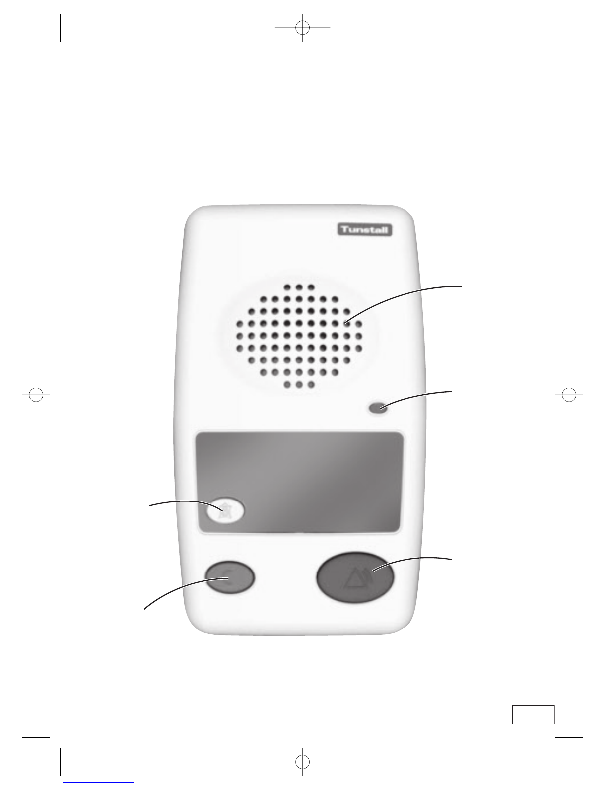
Away
Button
(optional)
Cancel
Button
Speaker
Handsfree
Illumination LED
Red Alarm
Button
3
Your Lifeline 400
Lifeline 400 user guide q6 18/2/04 10:56 am Page 4
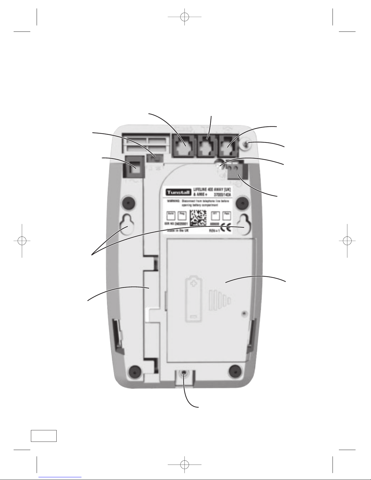
Your Lifeline 400
Tunstall Accessory
Port (G)
Telephone
Adaptor Socket (B)
Aerial
Ringer on/off Switch
(D)
Mains Adaptor
Socket (C)
Wall
Mounting
Points (H)
Cable
Channel (I)
Telephone Lead
Socket (A)
Speaker Volume
Control (E)
Hard Wired
Input (F)
Battery
Compartment (J)
Microphone (K)
4
Lifeline 400 user guide q6 18/2/04 10:56 am Page 5
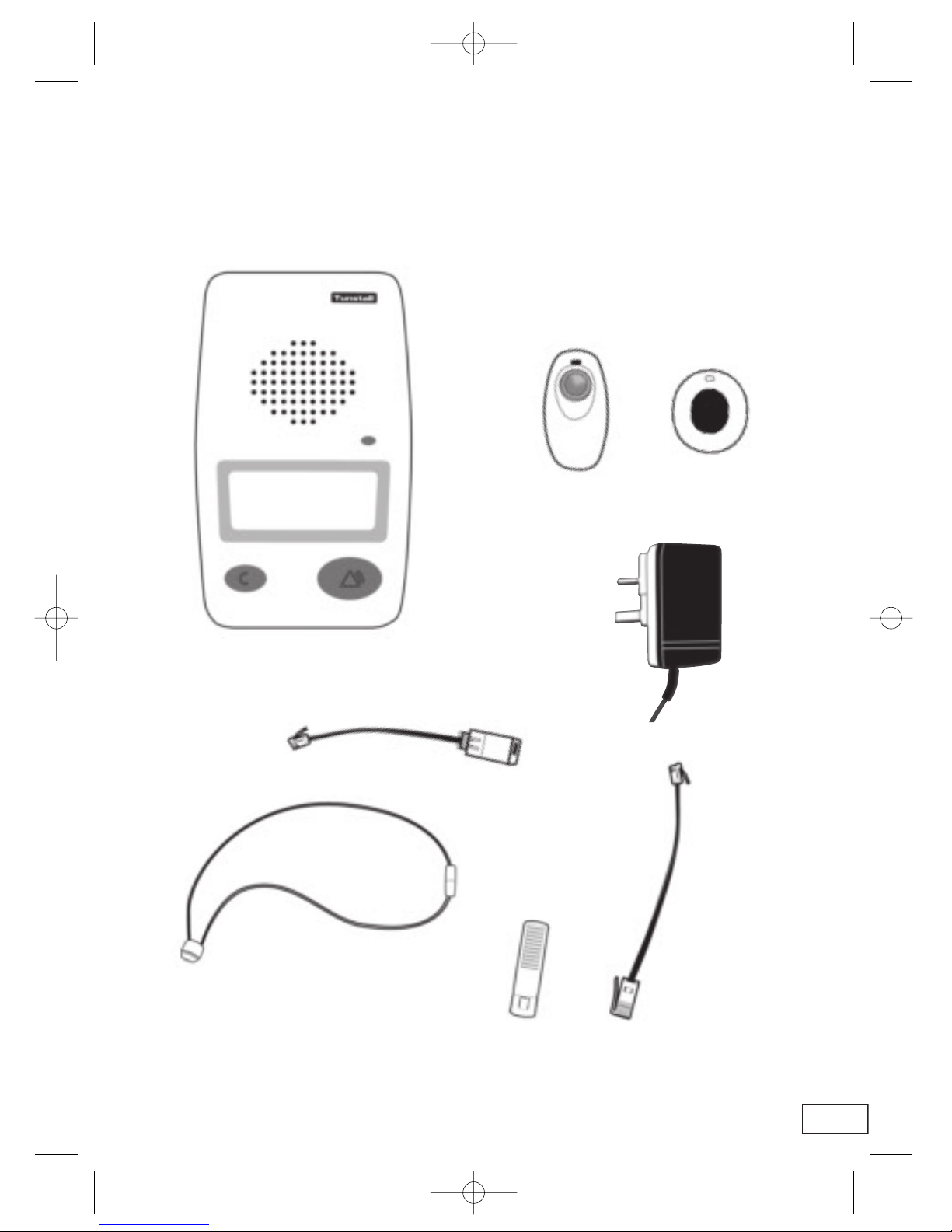
What’s in the box
Lifeline 400
Personal Triggers
Mains Adaptor (C)
Neck Cord
Telephone Adaptor (B)
Belt Clip
(Amie+ only)
Amie+
Gem+
Telephone
Lead (A)
5
OR
Lifeline 400 user guide q6 18/2/04 10:56 am Page 6
Setting Up The L
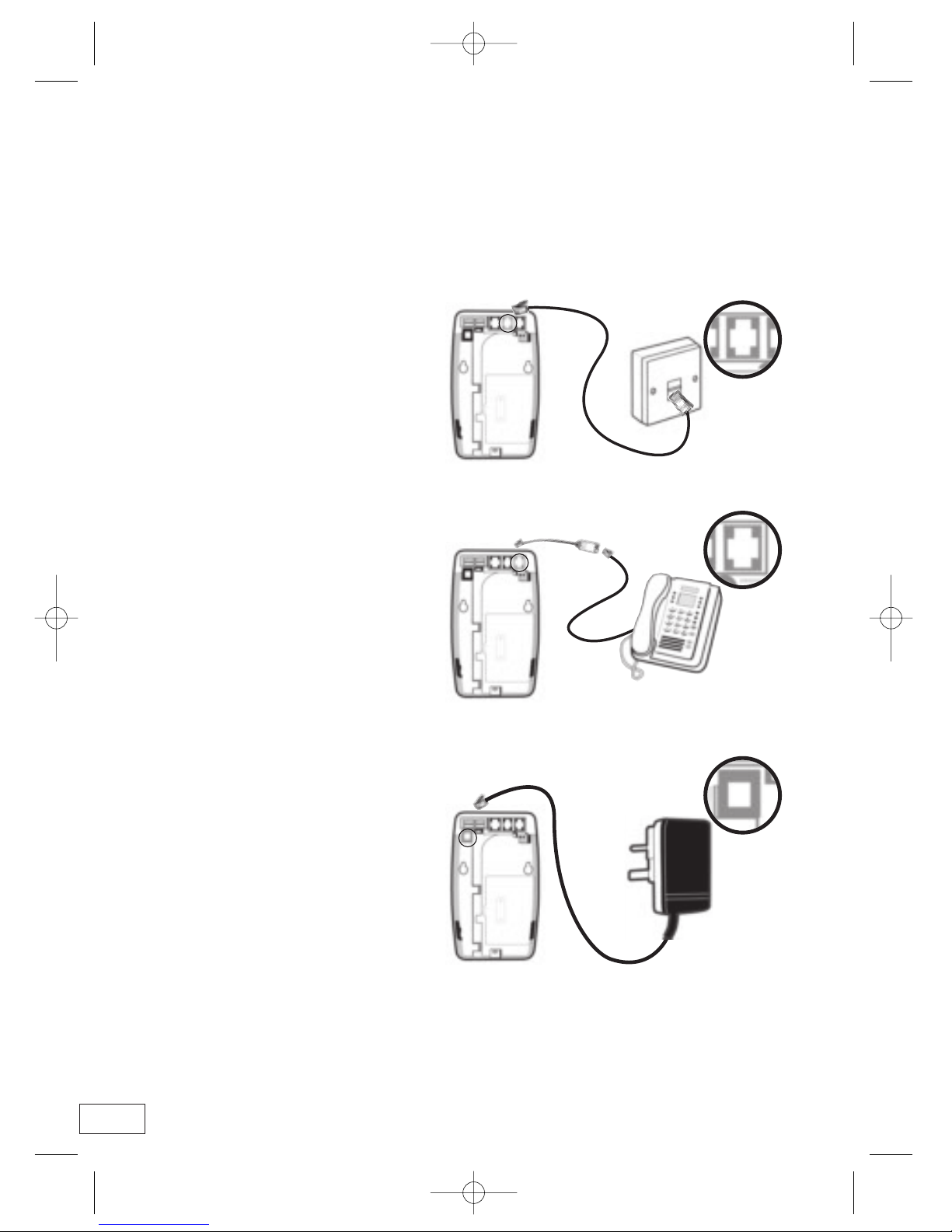
STEP 1
• Plug the telephone lead (A)
into the Lifeline 400 (Socket A) and
the main telephone wall socket.
STEP 2
• Plug the telephone adaptor (B)
into the Lifeline 400 (Socket B)
and then connect the
telephone to the adaptor.
STEP 3
• Plug the mains adaptor (C) into the
Lifeline 400 (Socket C) and then
connect to mains power.
6
Lifeline 400 user guide q6 18/2/04 10:56 am Page 7
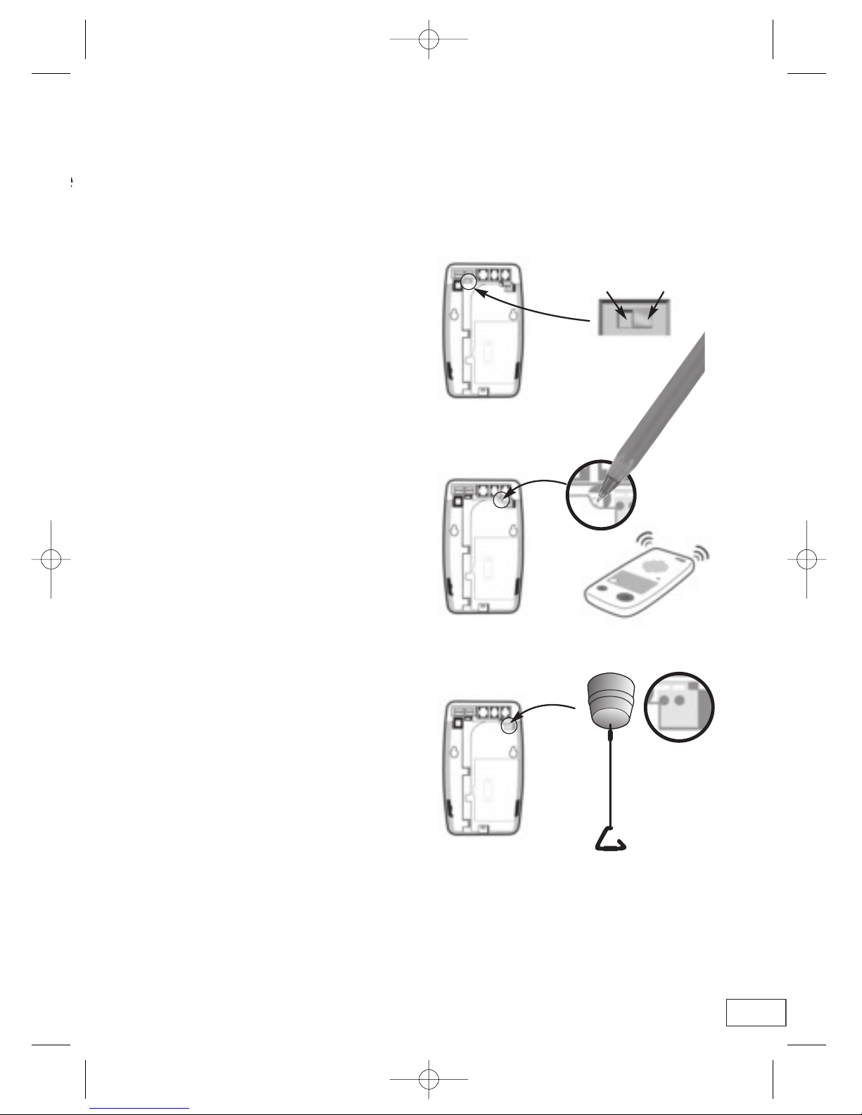
STEP 5
• Adjust speaker volume control (E)
by depressing with a pen/pencil.
STEP 6
• Connect hard wired peripheral
to input (F) (if required).
STEP 7
• Make test calls using the alarm button on the Lifeline 400
and each radio/hardwired peripheral.
STEP 4
• Adjust the ringer switch (D)
to the on or off position.
7
ON OFF
Lifeline 400 user guide q6 18/2/04 10:56 am Page 8

Installation Advice
USING EXTENSION PHONES
• Plug all extension phones into
Lifeline 400 to ensure
disconnection of normal
telephone calls
when an alarm
call is made.
USING CORDLESS PHONES
USING SMART BOXES/MODEMS
• Always plug the Lifeline 400
directly to the main telephone
socket. Equipment such as
modems/smart boxes
should be connected via the
Lifeline 400.
MAXIMISING AERIAL RANGE
• To maximise aerial
range, ensure that it is
positioned behind the
back of the Lifeline 400.
25 - 50 metres typical range
• Ensure that the base/charger,
which is registered to all handsets
in use, is connected
to the Lifeline 400,
via the telephone
adaptor (B).
8
Smart box/modem
2 way socket (not supplied)
Lifeline 400 user guide q6 18/2/04 10:56 am Page 9
9
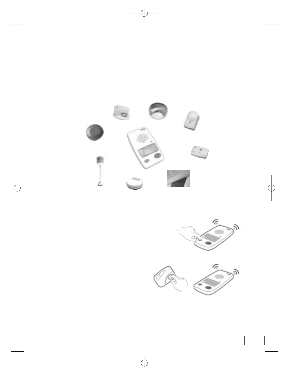
PERIPHERALS AND SENSORS
PROGRAMMING A PLUG AND PLAY RADIO PERIPHERAL
• The Lifeline 400 can be used with an extensive range of peripherals and sensors to provide a
comprehensive monitoring solution, tailored to the needs of each individual user.
Intruder/ Inactivity Sensor
CO Detector
Pressure Mat
Flood Detector
Pull Cord
GEM-Special needs
Personal Radio Trigger
Fall Detector
STEP 1
• Press the green cancel key for 5 seconds, the
Lifeline 400 will bleep once. Release the cancel
key, the Lifeline 400 bleeps twice.
STEP 2
• Press the green cancel key again for a further 3 seconds,
the Lifeline 400 bleeps once. Release the cancel key,
the Lifeline 400 bleeps twice.
STEP 3
• Activate the peripheral - Lifeline 400
will bleep to confirm acceptance.
STEP 4
• Press and release the green cancel key. The Lifeline 400
will bleep.
STEP 5
• Make a test call using the programmed peripheral.
Smoke Detector
Lifeline 400 user guide q6 18/2/04 10:56 am Page 10

Making an Alarm Call
STEP 1
• To raise an alarm call press
the radio trigger or the alarm
button on the Lifeline 400.
10
Lifeline 400 user guide q6 18/2/04 10:57 am Page 11

STEP 2
• The user talks to the
control centre operator
‘handsfree’ using the
powerful speaker and
microphone of the
Lifeline 400.
STEP 3
• The control centre
operator summons the
appropriate help from
a carer, warden or the
emergency services.
11
Lifeline 400 user guide q6 18/2/04 10:57 am Page 12

Cancelling an Alarm Call
LIFELINE 400
• To cancel an alarm call made
from the Lifeline 400, wait 5
seconds and press the green
cancel key. This in-built delay
prevents false cancellation of
an alarm call.
RADIO TRIGGER
• To cancel an alarm call made from the radio trigger,
press the green cancel key.
An alarm call from a radio trigger can be cancelled
straight away by pressing the green cancel key.
12
Lifeline 400 user guide q6 18/2/04 10:57 am Page 13

The Amie+ Personal Radio Trigger
Wrist Strap (optional)
Neck Cord
Auto Battery Low
Visual Call Indicator
Visual Call Indicator
Typical Range 25-50m
Belt Clip
• The trigger will
automatically raise a
notification call to the
control centre when its
battery is low.
The Gem+ Personal Radio Trigger
Auto Battery Low
Water Resistant
Typical Range 25-50m
• The trigger will automatically raise a
notification call to the control centre
when its battery is low.
13
Wrist Strap (optional)
Water Resistant
Lifeline 400 user guide q6 18/2/04 10:57 am Page 14

TELEPHONE LINE MONITORING
• If the telephone line is faulty or becomes disconnected, Lifeline 400 will sound a
warning bleep after 1 minute which will be repeated every second until the
telephone line becomes available again.
• To silence the bleep, re-connect the telephone line. If the telephone line is connected and the unit
continues to bleep, press the green ‘cancel’ key – if the bleep continues you should then notify
your telephone line supplier (e.g. British Telecom).
POWER FAILURE MONITORING
• If there is a power failure, the Lifeline 400 will continue to work but its alarm button
will flash repeatedly. It will also bleep rapidly 10 times.
If the failure lasts more than 1 hour, the unit will automatically dial the control centre.
This will be repeated every 4 hours until power is restored.
14
ANSWERING CALLS REMOTELY
• The personal radio trigger can be used to answer calls remotely by pressing its
button while the Lifeline 400, or a connected telephone is ringing.
To end the call, press the radio trigger again.
Lifeline 400 user guide q6 18/2/04 10:57 am Page 15
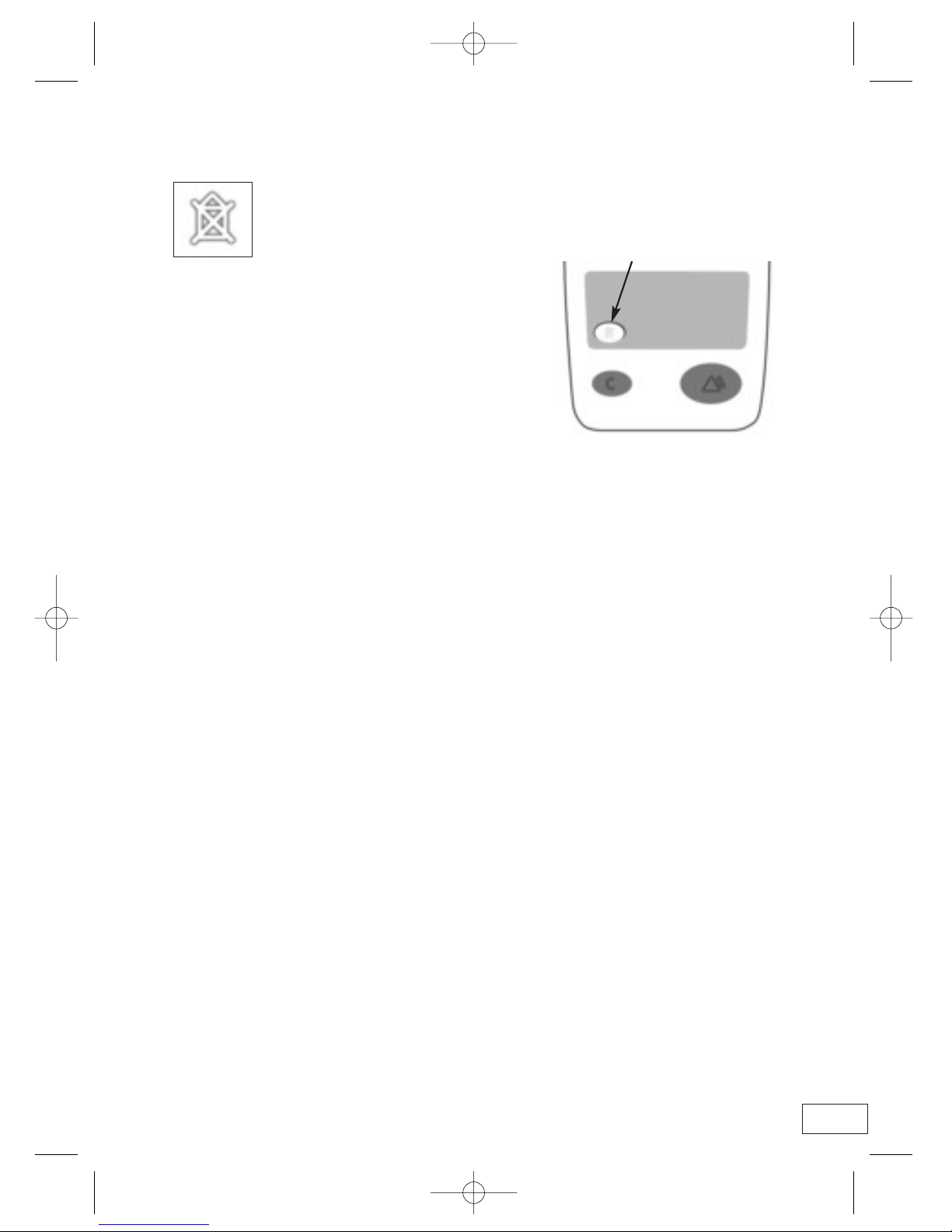
AWAY BUTTON
If your Lifeline 400 has an ‘AWAY’ button, you can use this to do the following:
• Activate/de-activate Inactivity Monitoring.
- Press once to de-activate inactivity monitoring
(the ‘AWAY’ button will be illuminated).
- Press again to activate inactivity monitoring
(the ‘AWAY’ button will not be illuminated).
‘AWAY’ Button
15
Intruder Monitoring
Your Lifeline 400 can be used to provide a very effective, simple to use intruder alarm facility,
which will alert a monitoring centre or personal recipient on detection of an intruder, while also
providing audible verification of the intrusion.
ARMING THE INTRUDER FUNCTION
When activated, you should arm the intruder function when leaving your dwelling either by
pressing the ‘AWAY’ button on your Lifeline 400 (note-some models do not have an ‘AWAY’
button) or by pressing the blue button on the arm/disarm trigger (optional).
When the intruder function has been armed, the ‘AWAY’ button will be illuminated and your
Lifeline 400 will sound its entry/exit tones.
On hearing the entry/exit tones you should now leave your dwelling and lock the door behind
you.
DISARMING THE INTRUDER FUNCTION
When you walk back in to your dwelling, the Lifeline 400 will sound its entry/exit tones again
and this time you should disarm the intruder function in order to prevent an alarm from being
raised.
You can do this in one of the following three ways depending on how your Lifeline 400 has
been set up:-
• Lift the handset of your connected telephone and type in the 4 digit PIN
number that was given to you when the Lifeline 400 was installed.
• Press the ‘AWAY’ button and then press your personal trigger straight away.
• Press the blue button on your arm/disarm trigger.
When the intruder function has been disarmed, the entry/exit tones will stop and the ‘AWAY’
button will no longer be illuminated.
Lifeline 400 user guide q6 18/2/04 10:57 am Page 16

16
ZONING
If you live in a house with your bedroom upstairs, it is possible to protect the downstairs area at
night while still being able to move around upstairs without raising an alarm.
You can do this in the following two ways:-
• ‘AWAY’ button versions only- Before going upstairs to bed, press and hold down the
‘AWAY’ button on your Lifeline 400. Whilst the ‘AWAY’ button is still held down,
press and release the cancel key. Finally, release the ‘AWAY’ button. This has now
armed the downstairs intruder alarm function.
On doing this, the ‘AWAY’ button will be illuminated and your Lifeline 400 will sound
its entry/exit tones. When you hear these tones, you should make your way upstairs
before they stop.
• Optional ‘zoning’ trigger- if you have been provided with a wall mounted ‘zoning’
trigger (with a blue button) at the top of the stairs, before going to bed, press the
blue button. This has now armed the downstairs intruder alarm function.
Having armed the ‘zoned’ intruder function, it is important to disarm the function straight away
when you go back downstairs either at night or in the morning, by using your chosen disarm
method as this will prevent false intruder alarms from being generated.
INTRUDER FUNCTIONALITY AND INACTIVITY MONITORING
If your Lifeline 400 has been set up to monitor for inactivity as well as intruders, inactivity monitoring will automatically be suspended the moment intruder monitoring is armed. When intruder
is monitoring is disarmed, inactivity monitoring will automatically be restored.
PANIC BUTTONS
If you have been supplied with optional wall mounted panic buttons (perhaps by your bed) you
can use these to manually raise intruder alarm calls if you feel unsafe.
BOGUS CALLERS
If you have been provided with an optional bogus caller button mounted next to your front
door, you can use this to summon help if you feel threatened by anyone trying to persuade you
to let them in against your will.
DEALING WITH FALSE ALARMS
If you generate a false intruder alarm call, please do not worry as your monitoring centre is
always happy to hear from you.
Lifeline 400 user guide q6 18/2/04 10:57 am Page 17

Help and Advice
IF YOUR LIFELINE 400 DOES NOT WORK:-
• Ensure that the telephone lead is plugged into the main telephone socket. - See step 1 - page 6.
• Ensure that the mains adaptor is plugged in. - See step 3 - page 6
• Ensure that the power supply is switched on (the alarm button should be lit). - See step 3 - page 6.
MOISTURE
• Don’t position your Lifeline 400 where it may come into contact with water or moisture.
• The personal radio trigger is water-proof but is not designed for complete immersion over
extended periods of time. For example, it should not be worn in the bath.
PERSONAL RECIPIENTS
• Lifeline 400 can be used to make an alarm call to the personal recipient (e.g. a relative) before
calling a monitoring centre. Please contact your monitoring centre to enable this facility.
CLEANING
• Dust with a soft cloth which can be moistened with a gentle detergent if required.
!
••
17
Lifeline 400 user guide q6 18/2/04 10:57 am Page 18
18
Notices
DISPERSED ALARM
Approval:This product is marked with a CE mark and constitutes a Class 1.2 device.
The whole dispersed system has been designed to comply with EN50134 series of European Norm standards specific to Social
Alarms.
The product exceeds the requirement for Electromagnetic Compatibility (EMC) standard BS EN 50130 part 4; which sets criteria for
EMC Immunity for components of fire, intruder and social alarm systems.
Intended Use: The product is intended to be connected either to an analogue single PSTN line or a compatible PABX as an extension
instrument. It cannot be guaranteed that the apparatus will operate under all conditions of connection to compatible PABX’s.
The supported features are: Pulse / Tone Dialling, Incoming Call Indication,Automatic Call Initiation along with Multiple Repeat Attempts,
Series Connection & Handsfree.
Ringer Equivalence Number (REN) = 1.0.The sum of all the RENs on one line should not exceed 4.
Safety: DO NOT attempt to open the Lifeline, authorised personnel only should open the unit.
The telephone line must be disconnected before the battery compar tment lid is removed.
Only provide power from a 9Vrms, 1A Transformer, par t number XD3606004 or XD3606003.
Battery Disposal Policy: The Lifeline and radio trigger batteries must be disposed of in an approved manner. In the event that the
radio product indicates a ‘battery low’ condition, contact your supplier for details of disposal/product replacement.
RADIO
The radio triggers (and receiver) are in accordance with the specific European Social Alarm radio frequency band allocation (from
869.20 to 869.25MHz).They operate at 869.2125 MHz.
The radio transmitters comply with mandatory radio standards for Short Range Devices (SRD) ETSI EN 300-220:The radio receiver
also conforms and exceeds the mandatory class 1 criteria necessary for “Highly reliable SRD…serving human life inherent systems.”
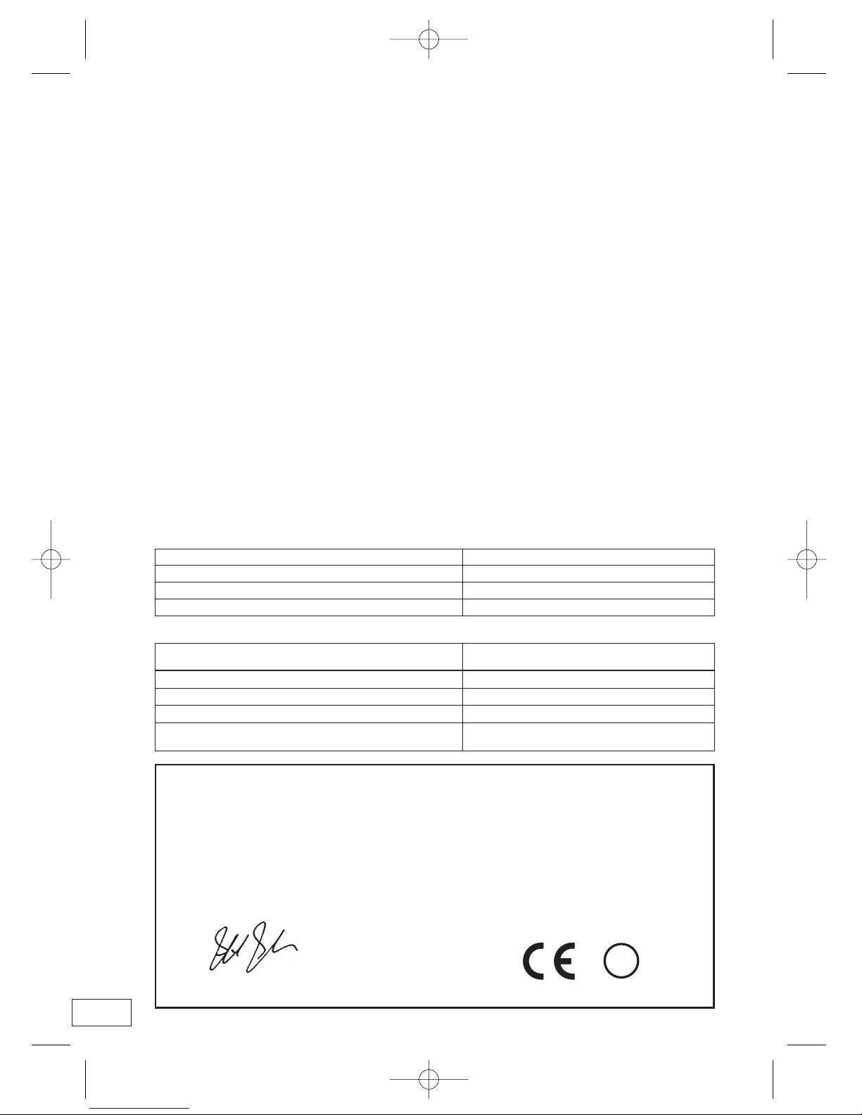
Receiver parameters (typically, in accordance with EN50134-3)
Conducted Sensitivity –111dBm Field sensitivity 25dBuV/m
Spurious response rejection, out of band >75dB Adjacent Channel Selectivity 70dB
Intermodulation response rejection 66dB at 3MHz offset Blocking 87dB
Co- channel rejection –7dB
Transmitter parameters
The transmitter follows a pre programmed cycle leading A class 2.7 device
to a typical duty cycle class of 1 (<0.1%):
Effective radiated power 100 micro Watts Frequency error ± 3 kHz maximum
Adjacent channel power <100 nano Watts
Effective range 25 to 50m (into standard alarm telephone) Intended area for use is Europe
Intended environment is group II- indoor in general with Expected battery life 20000 operations
intended operating temperature between –10 to +55 Celsius over 5 years
DECLARATION OF CONFORMITY
We,Tunstall Telecom of Whitley Lodge,Whitley Bridge, Yorkshire, England, DN14 0HR
declare that the Lifeline 400 dispersed alarms conform with the essential requirements of the RTTE directive 1999/5/EC.
Essential radio test suites have been carried out.
Model Numbers: 370ab/xy0 ab = territor y variant, x = Away or non Away, y = radio transmitter type
Applicable standards:
EMC EN 55022:1998, EN 55024:1998,EN 61000-3-2:1995, EN 61000-3-3:1995,
ETSI 300-683:1997 (class 1)
Safety EN 60950:2000
Radio ETSI EN 300 220-3:(2000-09)
Social Alarm EN50130-4:1995 + amendment A1:1998
Signed
Technical Director Date 14 June 2002
Associated Summary Information (02RTTE008A) The CE mark was first applied in June 2002
!
Lifeline 400 user guide q6 18/2/04 10:57 am Page 19

Wall Mounting
STEP 1
• Cut out template
STEP 2
• Fix to wall and
drill holes
STEP 3
• Attach screws to wall
STEP 5
• Place cables in cable channel for a neat
appearance.
Template
19
STEP 4
• Locate wall mounting points
with screws
88mm
Lifeline 400 user guide q6 18/2/04 10:57 am Page 20
www.tunstallgroup.com
Our policy of continual development means that product specification and appearance may change without notice.
Tunstall Telecom Limited is a member of Tunstall Group Ltd. © 2003 Tunstall Group Ltd.
® TUNSTALL and LIFELINE are registered trade marks of Tunstall Telecom Limited.
Tunstall Telecom Limited, Whitley Lodge, Whitley Bridge, Yorkshire DN14 0HR
Telephone: 01977 661234 Facsimile: 01977 662450 e-mail: sales@tunstall.co.uk
Lifeline 400 user guide q6 18/2/04 10:56 am Page 1
 Loading...