

Carefully review and save this guide for set up instructions and
an explanation of the features and functions of your PERS.
Personal Emergency Response System (PERS)
Model 850
& 850XL
Installation and User Guide
Service Provider:
INTERACTIVE VOICE
COMMUNIC
ATIONS
850105 R2.0

2
B
C
Included with your system are the following items:
A. Console Unit
B. A/C Wall Transformer (PN 800-01)
C. 10 ft.Telephone Line Cord (PN 800-10) 8 to 6 Pin
D. Help Activator (shown as pendant, optional accessories are
available for wrist, wall mount and belt clip configurations)
What’s in the Box
NOTE: Personal Help Activators are Console Unit specific.
Model 850XL is compatible with Activators: 490-GOLD, 495 & 497.
Model 850 is compatible with Activators: 285-P, 290 & 295.
A
D
Personal Help
Activator Accessories
Wall Mount
Belt Clip
Wrist Band
The Model 850(XL) Personal Emergency Response System (PERS) has
been designed for your ease of use, peace of mind and security. Using
your home telephone line and A/C power outlet, your PERS provides
immediate two-way voice communication between you and a trained
operator at the Response Center.
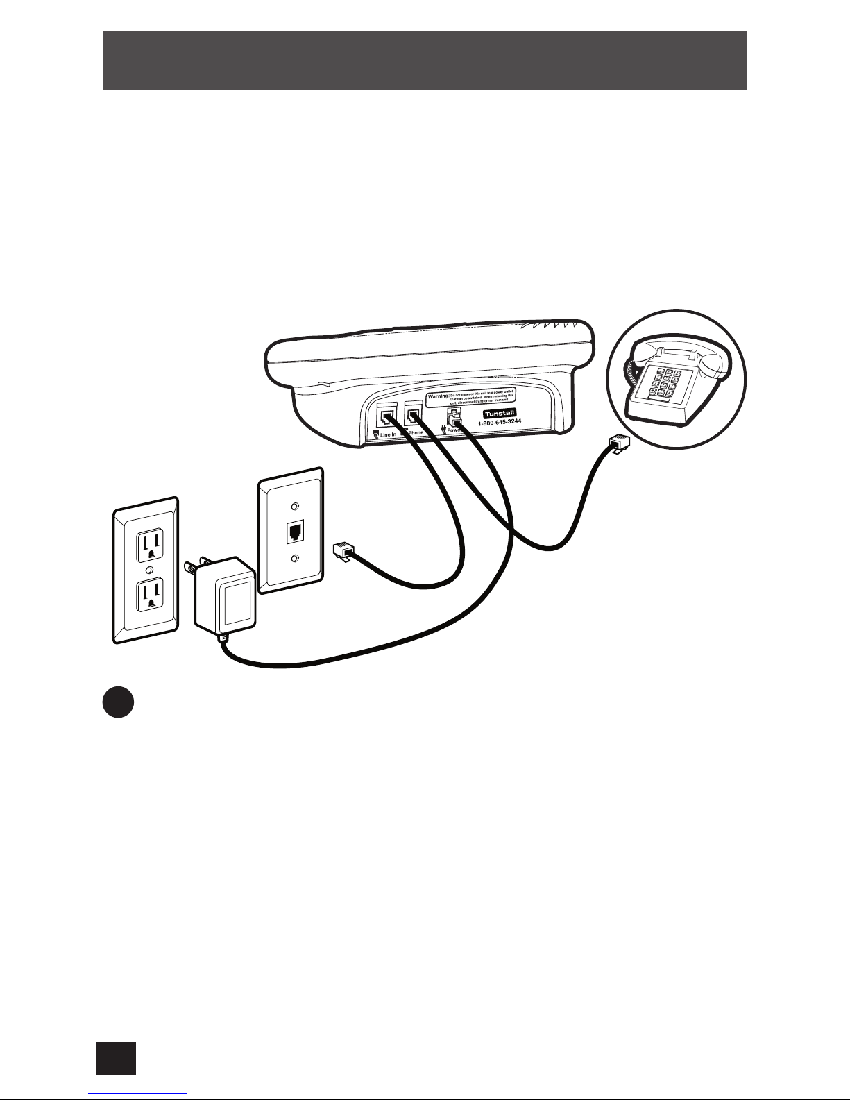
3
A. Plug the A/C Wall Transformer into an electrical outlet that is powered
at all times. Be sure the outlet is not controlled by a wall switch.
B. Insert the small end connector of the A/C Wall Transformer into the
plug on the rear of the Console Unit labeled POWER. You will hear a
series of beeps. The green POWER light will illuminate.
NOTE: For safety purposes the Console Unit does not have a
traditional ON/OFF switch.
C. Insert the wider end of the supplied telephone line cord into the
connector on the rear of the Console Unit labeled LINE IN.
D. Disconnect the telephone from the telephone jack and insert it into
the port on the Console Unit labeled PHONE. Plug the supplied
telephone cord into your home phone jack.
Installation
Installation Diagram
Console
Unit
A/C
Power
Outlet
Telephone
Jack
Existing
Telephone
UNIT POWER REQUIREMENTS
AND RATINGS:
Power requirements: 120 VAC @ 1A
Power Rating: 9 VDC @ 300 mA
Maximum Charging Current: 100 mA
Battery Type: (1) VDC 800 mAh Nicd Battery
The initial setup of your PERS is important in providing a safe and reliable
service. Place the Console Unit in a central location in your home on
a sturdy, non-metallic surface near a modular phone jack and an A/C
power outlet. Do not install the Console Unit near noisy appliances, (i.e.
television, air conditioner, or stereo) or place unapproved items on top
of your PERS as it this could interfere with the operation of your system.
Please consult your service provider for a list of approved devices which
may be placed on top of the Console Unit.
1 Connecting the Console Unit

4
Installation (cont.)
2 Help Activator Range Test
Please conduct the Help Activator range test when you install or relocate the
Console Unit. Follow these simple steps to perform the test:
A. Press and hold the RESET button on the Console Unit. While holding
down the RESET button, press and hold the HELP button. Release
your finger from the RESET button and then from the HELP button.
The Console Unit will beep several times indicating it is in the range
test mode. It will remain in this mode for the next three minutes.
While in this mode, a signal cannot be transmitted to the Response
Center.
NOTE: If the Console Unit does not successfully enter the test mode,
press the RESET button and repeat step A.
B. Test the range of your activator(s) by pressing the button from
different locations in your home. If you are within range, the Console
Unit will beep several times.
C. To exit this mode before the three minute test period has elapsed,
press the RESET button.
NOTE: It is important to test activator(s) in all the areas of your home
as environmental conditions such as furnishings, building structure,
etc. may affect the range.
3 Activating Your PERS
Press your Help Activator Button. The Console Unit will beep and transmit a
signal to the Response Center. An operator will communicate with you over
the Console Unit to provide programming assistance.
After the initial communication and programming, press the RESET Button
on the Console Unit.
Proceed to send in a second signal using your Help Activator to confirm
system programming and verify personal and responder information. Your
installation is now complete!
E. Pick up your telephone receiver and verify that dial tone is present.
If you do not hear a dial tone, check your telephone line and
Console Unit connections. Please consult the Indicator Lights and
Troubleshooting section on page (12) to identify the problem and
resolution.

5
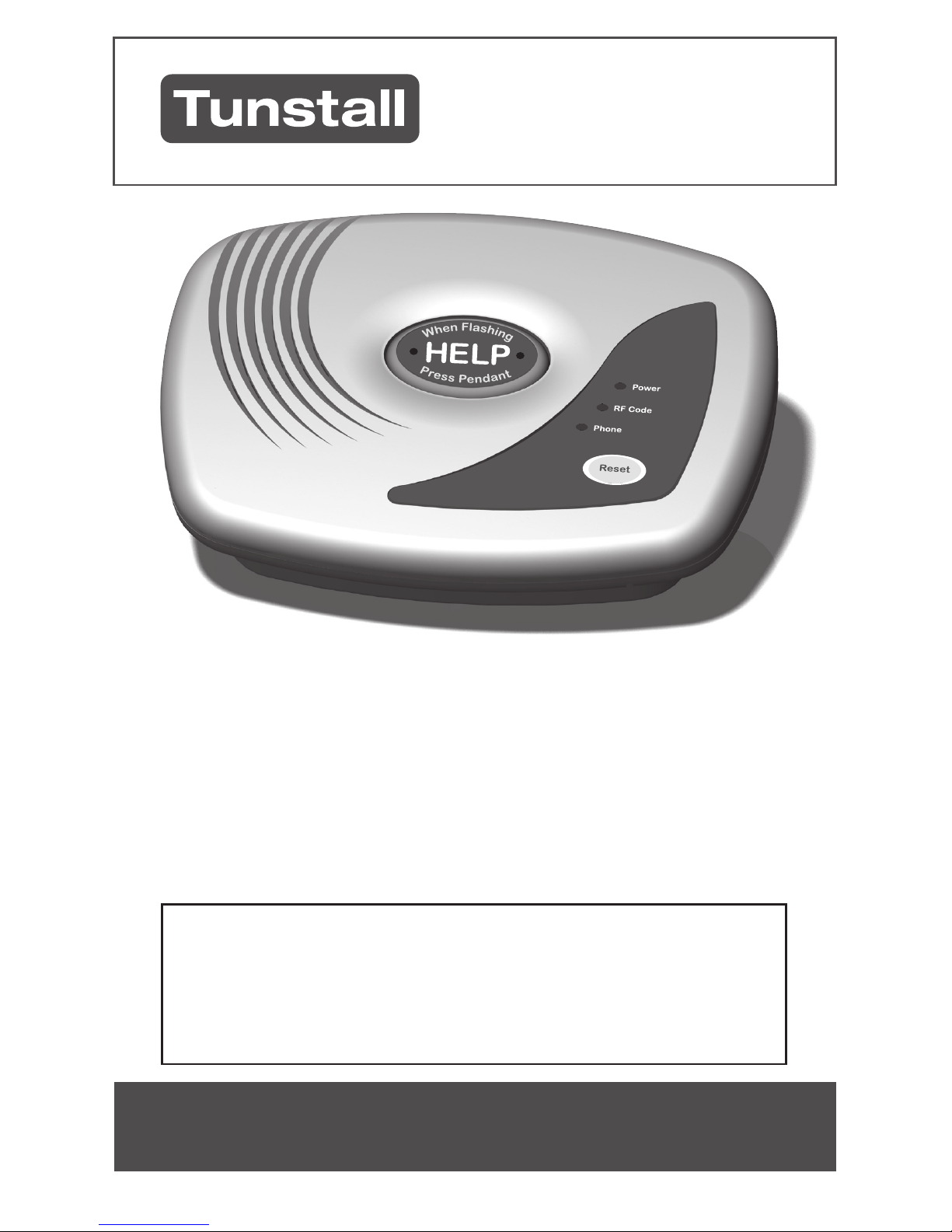
The Console Unit
1
HELP Button
(illuminated)
Press to transmit a signal to the Response Center.
2
RESET Button Press to cancel a signal and/or reset your PERS.
3
POWER Light Indicates if the Console Unit is operating on A/C
(steady) or D/C (flashing) power.
4
RF CODE Light Provides a visual indicator when radio frequency
activity is detected near the unit.
5
PHONE Light Indicates the condition of the telephone line and
transmission of a signal to the Response Center.
6
TEST Reminder Light Provides a visual reminder to test your PERS with
your Help Activator.
NOTE: To conserve battery life, the HELP Button is not illuminated
on battery power, but still transmits a signal when pressed. All other
system functions are operational while on battery power. Please refer
to the Indicator Lights and Troubleshooting section for additional
information.
4
1 2
5
3
6
BATTERY BACKUP
The Console Unit must always be securely plugged into an A/C power outlet and
connected to your telephone line. The unit is equipped with an internal back-up
battery which will power the unit for approximately 24 hours in the event of a power
failure. If the unit continues to be powered by its internal back-up battery, a silent
signal will automatically transmit to the Response Center. A trained operator will
call you to troubleshoot the problem.
Controls and
Features:
6
Press the HELP button on the Console Unit or the button on
your Help Activator. The Console Unit will emit a beeping tone,
indicating it is dialing the Response Center. Upon receiving your
signal, a trained operator will communicate with you through the
unit to determine the nature of your call and dispatch assistance
if necessary. It is not necessary to continue to depress the button
to communicate. If you are unable to speak or can not be heard,
the operator will follow the “no voice contac
t” instructions on your
subscriber information form.
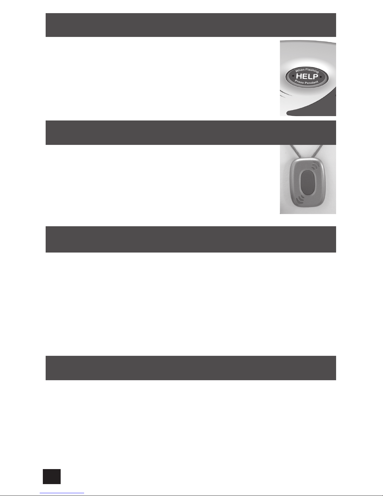
Your Help Activator allows you to summon for help within range of
the Console Unit. When pressed, the indicator light should steadily
illuminate and activate the Console Unit. Your Help Activator is
powered by a long-life lithium battery, designed to last 2-3 years
depending upon use. When the battery is low, the indicator lights
will flash. Please contact your Service Provider or Response
Center if your Help Activator is not working o
r lights are flashing.
When You Need Help
Help Activator
Shown as Pendant
Your PERS should be tested monthly using your Help Activator. When the operator
answers your call, inform them that you are testing.
Testing Tip: Test your PERS on the day of the month you were born, i.e. if you
were born on May 15
th
, conduct the test on the 15th of each month.
Monthly Test Reminder
Your PERS contains a test reminder light to prompt you to test your PERS on a
monthly basis using your Help Activator. If your PERS has not been activated
with the Help Activator, the reminder light on the Console Unit will flash. Press
the button on your Help Activator to send in a signal and reset the reminder.
Testing Your PERS
A red Silent Panic Activator may be provided for enhanced protection. In situations
where you are concerned about your personal safety, press the red Silent Panic
Activator to send a silent signal to the Response Center. The operator will listen in
to determine the appropriate response. If you are in danger, the operator will notify
the Police. If you do not appear to be at risk, the operator will telephone you to
verify your safety by asking for your security password.
NOTE: All activators comply with part 15 of the FCC rules. Operation is subject
to the following two conditions: (1) This device may not cause harmful interference and (2) thus device must accept any interference received, including
interference that may cause undesired operation.
Silent Panic Activator

7
If you are permanently or temporarily moving to a new or second home, you may
elect to take your PERS with you. Please coordinate this relocation with your local
service provider or call Client Services 1-800-645-3244.
Note, monitoring services cannot be provided without proper notification to
update your household and responder information.
New or Second Home Connection
(Optional Feature: To activate the RF answer feature, contact the Response Center
or your Service Provider)
Your PERS contains a special feature that allows you to answer incoming telephone
calls with your Help Activator.
Step 1 After the telephone rings twice, press your Help Activator to answer the
phone. The red phone light on the unit will illuminate to inform you that
the system has answered the call.
Note: It is not necessary to hold down the Help Activator button to
communicate with the caller.
Step 2 Talk loudly in the direction of the unit to communicate with the caller.
Step 3 To terminate the call, press your Help Activator until the Red Phone Light
on the Console Unit goes off.
Auto Disconnect – The unit will allow you to conduct a hands-free phone
conversation in five minute increments. At approximately 4 minutes and 45
seconds, the unit will beep four times to inform you that the unit is approaching the
five minute reset point. If you would like to continue your conversation, instruct the
caller to press any digit on their phone to extend the conversation for another five
minutes. Repeat as needed.
Using Your System as a Speaker Phone

8
Notify your Service Provider in writing of any changes to your personal or
responder information.
Keep the area around the Console Unit clean.
Do not spill any liquids or attempt to wash any system component.
Immediately report system failures or the loss of any component.
Never tamper with or relocate the Console Unit.
If you plan to move or want to relocate the Console Unit, call your Service
Provider for information on how to remove and reconnect your PERS.
A fundamental device or operation which has not been evaluated and tested
to the requirements of this standard shall not replace a device that was
evaluated and tested to the requirements of this standard as part of NCS.
NOTE: Failure to comply with any of these cautions voids your system
warranty.
General Suggestions &
Important Safeguards
.
.
.
.
.
.
.
.
WARNING:
The operation of your PERS is dependent upon compatible phone service. A
change in telephone service after proper installation may render the system
inoperative. If phone service is changed or modified, subscriber must verify
system compatibility by successfully activating the PERS with the Response
Center. If the signal is not received by the Response Center, phone service
may not be compatible and the PERS will not operate as intended.
Enhancing your Pers optional features
SMOKE MONITORING
If your Model 850(XL) includes a smoke detector which emits a loud audible tone
and alerts the Emergency Response Center if a smoke condition is detected in your
home. When the smoke detector signals the Emergency Response Center, two-way
voice communication is immediately established allowing the Operator to verbally
notify you of the signal and to verify if an actual emergency exists.
If you are not at home
or unable to speak, the Fire Department will be notified
immediately.
NOTE: ALL SMOKE DETECTORS COMPLY WITH PART 15 OF THE FCC RULES. OPERATION IS
SUBJECT TO THE FOLLOWING TWO CONDITIONS: (1) THIS DEVICE MAY NOT CAUSE HARMFUL
INTERFERENCE AND (2) THUS DEVICE MUST ACCEPT ANY INTERFERENCE RECEIVED, INCLUDING
INTERFERENCE THAT MAY CAUSE UNDESIRED OPERATION.
NOTICE
Similar to wearing a necklace, chain or other item around your neck, the activator neck cord
can pose a potencial risk since it can become entangled or caught thereby causing possible
injury. When wearing your activator neck cord, please be cautious to prevent it from becoming
entangled or caught on any other item.
As an alternative to utilizing the activator neck cord, we offer the wrist activator as an option.
If you would like to obtain an alternative activator please contact us at 1-800-645-3244.

9
Your Console Unit is factory programmed to communicate with the supplied
Help Activator. On occasion, you may have to replace, add or integrate
additional activators or other types of devices (i.e. Silent Panic Button, Smoke
Detector) with the unit.
Auto-Learning Procedure:
The Console Unit can learn up to two different Radio Frequency (RF) codes.
To learn a new or add an additional Help Activator, follow the instructions
below:
Step 1 Press and hold the RESET Button on the unit. While holding the
RESET button, press the HELP button. Release your finger from the
RESET button and then from the HELP button on the Console Unit.
The unit will beep four times.* Immediately thereafter, press the
HELP button again. The unit will emit two long beeps indicating it is
now in the auto-learn mode.
Step 2 Press the new or additional Help Activator. The unit will emit one
long beep and then a series of quick beeps.
Step 3 Press the RESET button on the unit. The Console Unit has now
learned the new Help Activator.
Step 4 To verify Activator Auto-Learn, press the Activator button to send in
a signal. When the Console Unit begins to dial, press the RESET
button to cancel the call in process.
* Note: If the Console Unit does not beep four times, press the RESET
button to restart the Auto-learn procedure.
Activator Programming Scenarios:
Replacing a Help Activator – Auto-Learn the unit twice to the new
activator in order to fill both RF code spots.
Adding a second Help Activator – Auto-Learn the additional activator
only once. Be sure that both Help Activators activate the unit when
pressed.
Adding a Silent Panic Button - Call 1-800-645-3244 for programming
assistance.
Programming Activators
to the Console Unit
.
.
.

10
This equipment has been tested and found to comply with the limits for a Class B digital device, pursuant
to Part 15 of the FCC Rules. These limits are designed to provide reasonable protection against harmful
interference in a residential installation. This equipment generates, uses, and can radiate radio frequency energy
and, if not installed and used in accordance with the instructions, may cause harmful interference to radio
communications. If this equipment does cause harmful interference to radio or television reception, which can
be determined by turning the equipment off and on, the user is encouraged to try to correct the interference by
one or more of the following measures:
- Reorient or relocate the receiving antenna.
- Increase the separation between the equipment and receiver.
- Connect the equipment into an outlet on a circuit different from that to which the receiver is connected.
- Consult the dealer or an experienced radio/TV technician for help.
Users must not modify this device. Modifications by anyone other than the party responsible for compliance
with the rules of the Federal Communication Commission (FCC) may void the authority granted under FCC
regulations to operate this device. This product meets the requirements of 47 CFR Part 68 of the Federal
Communications Commission (FCC) Rules.
In the event of equipment malfunction, all repairs should be performed by our Company or an authorized agent.
It is the responsibility of users requiring service to report the need for service to our Company or to one of our
authorized agents. Service can be facilitated through our office at:
American Medical Alert Corp.
36-36 33rd Street
LIC, New York 11106
1-800-645-3244
NOTICE: Part 68, FCC Rules and Regulations permit this device to be directly connected to the telephone
network in the US. Standardized jacks are used for these connections. This equipment should not be used on
party lines or coin lines.
If trouble is experienced with this device, you should disconnect the Model 850(XL) appliance from the
telephone line to determine if it is malfunctioning. If the Model 850(XL) appliance is malfunctioning you
should discontinue use of the equipment until the problem has been corrected.
If the telephone company requests information on what equipment is connected to their lines, inform them of:
1. The telephone number this unit is connected to.
2. The Ringer Equivalence Number (REN), which is 0.1B.
3. The USOC jack required, which is RJ-31X.
The REN is used to determine how many devices can be connected to your telephone line. Excessive RENs on
a telephone line may result in the devices not ringing in response to an incoming call. The sum of the RENs of
all devices on any one line should not exceed five (5.0). If too many devices are attached, one or more may not
ring properly. To be certain of the number of devices that may be connected to a line, as determined by the total
RENs, contact the local telephone company.
This equipment complies with Part 68 of the FCC rules. Located on the bottom of this equipment is a label that
contains, among other information, the FCC registration number and ringer equivalence number (REN) for this
equipment. If requested, this information must be provided to the telephone company.
A plug and jack used to connect this equipment to the premises wiring and telephone network must comply
with the applicable FCC Part 68 rules and requirements adopted by the ACTA. A compliant telephone cord and
modular plug is provided with this product. It is designed to be connected to a compatible modular jack that is
also compliant. See installation instructions for details.
If this equipment, model 850(XL), causes harm to the telephone network, the telephone company will notify
you in advance that temporary discontinuance of service may be required. But if advance notice isn’t practical,
the telephone company will notify the customer as soon as possible. Also, you will be advised of your right to
file a complaint with the FCC if you believe it is necessary.
FCC Information
Equipment Information: Model: 850(XL)
Equipment Code: AL
Ringer Equivalence: (0.1B)
Ringer Type: B
Phone Jack: RJ31X
US: 5LTAL01B850

11
The telephone company may make changes in its facilities, equipment, operations or procedures that could
affect the operation of the equipment. If this happens, the telephone company will provide advance notice in
order for you to make necessary modifications to maintain uninterrupted service.
If trouble is experienced with this equipment, Model 850(XL), for repair or warranty information, please
contact:
For troubleshooting, refer to page 12 in this manual. If the equipment is causing harm to the telephone network,
the telephone company may request that you disconnect the equipment until the problem is resolved.
Connection to party line service is subject to state tariffs. Contact the state public utility commission, public
service commissions or corporation commission for information.
If your home has specially wired alarm equipment connected to the telephone line, ensure the installation of the
Model 850(XL) does not disable your alarm equipment. If you have questions about what will disable alarm
equipment, consult your telephone company or a qualified installer.
Electrical Safety Advisory
:
Parties responsible for equipment requiring AC power should suggest the customer use a surge arrestor.
Telephone companies report that electrical surges, typically lightning transients, are very destructive to customer
terminal equipment connected to AC power sources. This has been identified as a major nationwide problem.
Alarm Dialing Equipment
:
Alarm dialing equipment must be able to seize the telephone line and place a call in an emergency situation.
It must be able to do this even if other equipment (telephone, answering system, computer modem, etc.)
already has the telephone line in use. To do so, alarm dialing equipment must be connected to a properly
installed RJ31X jack that is electrically in series with and ahead of all other equipment attached to the same
telephone line. Proper installation is depicted in the figure below. If you have any questions concerning these
instructions, you should consult your telephone company or a qualified installer about installing the RJ31X jack
and alarm dialing equipment for you.
Important Note Regarding Line Seizure
:
If the Subscriber has more than one telephone extension using the same number, and if one of these phones is in
use or off the hook, the PERS will not operate without the installation of an RJ31X Telephone Jack as
depicted in the above illustration. Provider/Agency is not responsible for any costs for parts and/or labor
associated with installing an RJ31X jack and will be relieved of all liability if the PERS can not transmit
a signal to the Response Center if a phone is in use or off the hook.
Model 850
Customer Premises Equipment and Wiring
Alarm Dialing
Equipment
Computer
Telephone
Telephone
Line
Unused
RJ-11 Jack
Unused
RJ-11 Jack
RJ31X
Jack
Network
Service
Provider's
Facilities
Network
Demarcation
Point
Telephone
Telephone
Fax Machine
Answering System
American Medical Alert Corp.
36-36 33rd Street
LIC, New York 11106
1-800-645-3244

12
Indicator Lights and
Troubleshooting
If any message/symptom persists, call your Service
Provider or the Client Services Center at:
1-800-645-3244
Message/
Symptom
Description Remedy
Red PHONE
light is on.
Console Unit is
transmitting a call to the
Response Center.
Red PHONE
light is flashing.
Phone is in use, off the
hook or out of service.
Verify connection by picking up
your telephone receiver and
listening for a dial tone. If there
is no dial tone, there may be a
problem with your phone line
connection or service to your
home.
Red PHONE
light is off.
Normal operating mode.
Green POWER
light is on.
Normal operating mode.
Green POWER
light is flashing
Console unit is operating
on internal back-up
battery power.
Make sure that the A/C Wall
Transformer is securely plugged
into an electrical outlet. Check
to see if the electrical outlet is
controlled by a wall switch.
Green POWER
light is off.
Indicates there is no
power to the Console
Unit.
Check transformer connection at
rear of unit and electrical outlet.
Internal back-up battery may need
to be replaced.
Amber RF
CODE light is
on.
Indicates possible
problem with the
Console Unit.
Press the RESET button. If
light remains illuminated, call for
assistance.
Amber RF
CODE light is
flickering.
Occasional flickering
is normal. If flickering
is constant, there may
be a problem with the
Console Unit.
Press the RESET button. If
light continues to flicker, call for
assistance.
Amber RF
CODE light is
off.
Normal operating mode.
Red TEST light
is flashing.
Monthly test reminder.
TEST your system by pressing
your Help Activator. This will reset
the reminder feature.

13
Notes
Manufacturer:
Tunstall
100 Freight Street
Pawtucket, RI 02860
1-800-645-3244
USinfo@Tunstall.com

This Page Intentionally Left Blank

This Page Intentionally Left Blank

Installation and User Guide
850105 R2.0
 Loading...