

Page 1

Tünkers 8-Channel Motor Terminal
for controlling maximum 8 electronic clamping devices
TMI8 V2.1
TÜNKERS® Maschinenbau GmbH Am Rosenkothen 8 • D-40880 Ratingen Tel. 02102 4517-0 • Fax 02102 445808 Internet www.tuenkers.de
Operating Instructions
Subject to technical alterations Page -1- 06/03/2018
Page 2

Tünkers 8-Channel Motor Terminal
for controlling maximum 8 electronic clamping devices
TMI8 V2.1
TÜNKERS® Maschinenbau GmbH Am Rosenkothen 8 • D-40880 Ratingen Tel. 02102 4517-0 • Fax 02102 445808 Internet www.tuenkers.de
Contents
1. Product overview ............................................................................................................. 3
1.1 Block diagram ................................................................................................................. 3
1.2 Brief description .............................................................................................................. 3
2. Operating conditions and standards ............................................................................... 3
3. Description of the safety function .................................................................................... 3
4. Structure of the hardware ............................................................................................... 4
4.1 2-digit 7-segment display ................................................................................................ 4
4.2 Display LEDs for the fieldbus module ............................................................................. 4
4.3 Display LEDs for electric clamp 1 … 8 ............................................................................ 5
4.4 Display LEDs for general binary inputs ........................................................................... 5
4.5 KEBA terminal combination for manual mode ................................................................ 5
4.6 Connections .................................................................................................................... 5
4.7 Housing and mechanics .................................................................................................. 7
5. Function .......................................................................................................................... 7
5.1 Automatic ........................................................................................................................ 7
5.1.1 Data transmission Profinet IO / Ethernet-IP / Profibus-DP .............................................. 7
DeviceNet ....................................................................................................................... 7
5.1.2 Control program ................................................................ ................................ .............. 8
5.2 Manual mode .................................................................................................................. 9
6. Electrical characteristics ................................................................................................ 10
7. EG Declaration of Conformity ....................................................................................... 12
Subject to technical alterations Page -2- 06/03/2018
Page 3

Tünkers 8-Channel Motor Terminal
for controlling maximum 8 electronic clamping devices
TMI8 V2.1
TÜNKERS® Maschinenbau GmbH Am Rosenkothen 8 • D-40880 Ratingen Tel. 02102 4517-0 • Fax 02102 445808 Internet www.tuenkers.de
XS1
XS2
XE1
XE12
+24V
+24V
RS422
XBE
XBA
XA1
XA8
*
*
*
*
*
*
XS3
3,3V
Interne
Spannung
Ust = +24V
SteuerSpannung
Ul = +24V
LastSpannung
Initiatoren
Endlagenmeldung;
Allgemeine
Eingänge
Service
Anschluss
KEBA-Terminal
XBK
Feldbus:
DeviceNet
PROFIBUS-DP
PROFINET-IO
Ethernet-IP
Spannermotoren
+24V
+5V
+5V
1. Product overview
1.1 Block diagram
Protection category IP54 Protection category IP54 Protected against dust in harmful
amounts, complete contact protection
1.2 Brief description
The TMI8 control unit serves for controlling up to 8 electrically operated
clamping devices via a field bus interface. The device can be selectively controlled via DeviceNet, Profibus-DP, PROFINET IO or Ethernet-IP.
Next to the initiators for notifying the end positions Close or Open, up to
8 binary inputs can also be connected. The device can be configured
and the current operating states can be represented using a hand-held
terminal. The operating and error states can be displayed on the device
using the two-digit display.
Connections:
1 input / 1 output +24V control voltage
1 input +24V load voltage
8 inputs End position sensor Open / Close
4 inputs General inputs
1 input / 1 output Fieldbus (device variant DeviceNet,
PROFIBUS-DP, PROFINET-IO or
Ethernet-IP)
8 outputs Clamping motors
1 output Hand-held terminal
The control is galvanically isolated from the supply.
2. Operating conditions and standards
Safety
The safety function is only guaranteed with the TVM8Safety 230V or TVM8 Safety 400V connected.
Parameter Value Level achieved
MTTFd Classification: MTTFd = High Safe separation
Load voltage
PFHD Safe separation
Load voltage
Climate
Operation at 0° … 50° C
Storage at -20° … 70° C
Rel. humidity up to 80%, no condensation
and protection against splash water on all
sides
Service life 10 years
Regulations
EN 61326-1:2013 "Electrical equipment for measurement, control and
laboratory use - EMC requirements - Part 1: General requirements (IEC
61326-1:2012)“
EN 55011:2009 + A1:2010 "Industrial, scientific and medical equipment
- Radio-frequency disturbance characteristics - Limits and methods of
measurement (IEC/CISPR 11:2009, modified + A1:2010)“
3. Description of the safety function
The safety function in the TMI8 includes only the safe separation of the
load voltage from the other supply voltages. To guarantee the functional safety, the TMI8 must always be operated with a TVM8 Safety 230V
or TVM8 Safety 400V.
The functional safety is guaranteed by the safe switching
off of the load voltage on the XS3 by the voltage supply
modules TVM8-Safety 230V or TVM8 Safety 400V.
Subject to technical alterations Page -3- 06/03/2018
Page 4

Tünkers 8-Channel Motor Terminal
for controlling maximum 8 electronic clamping devices
TMI8 V2.1
TÜNKERS® Maschinenbau GmbH Am Rosenkothen 8 • D-40880 Ratingen Tel. 02102 4517-0 • Fax 02102 445808 Internet www.tuenkers.de
4. Structure of the hardware
4.1 2-digit 7-segment display
Status display:
AA Automatic mode without error
HH Manual mode if the had-held terminal is attached and the
function has been selected via the menu
AF Automatic mode with errors -> alternating display
with error code
AF Manual mode with errors -> alternating display
with error code
LS Manual mode with errors -> alternating display
with error code
FF Manual mode with errors -> alternating display
with error code
11 – 19 Error codes clamp channel 1
11 Error, the clamp remains stationary in the start po-
sition
12 3 sec timeout after initiating the command
13 Defective motor driver
14 Initiator error Close / Open
16 Deactivation via adjustable current limit values
21 – 86 Error codes clamp channel 2 - 8
4.2 Display LEDs for the fieldbus module
Green LED B1, B2, B3 and red LED B4 for displaying the fieldbus
status (XBA / XBE)
DeviceNet: B1 - Internal voltage supply 3.3 V On or Off
B2 - Flashes if Bus is OK ... but has not yet
started
Continuous illumination when the bus has been
started correctly
B3 - no function
B4 - no function
Profibus: B1 - Internal voltage supply 3.3 V On or Off
B2 - Continuous illumination when the bus has not been
started yet. Goes out when the bus is in the
data exchange mode
B3 - no function
B4 - no function
ProfiNet/ B1 - Flashes when a functional Ethernet is connected to
an XBA
Ethernet-IP: B2 - Off the bus has not started yet
Flashes 10 Hz error (ProfiNet only)
Flashes 2 Hz Bus started and waits for connection
(combination)
Illuminates when the connection has been estab-
lished
B3 - Flashes when a functional Ethernet is connected to
an XBE
B4 - Off, no error
Flashes ProfiNet participants flash test
Illuminates in case of bus error
Subject to technical alterations Page -4- 06/03/2018
Page 5

Tünkers 8-Channel Motor Terminal
for controlling maximum 8 electronic clamping devices
TMI8 V2.1
TÜNKERS® Maschinenbau GmbH Am Rosenkothen 8 • D-40880 Ratingen Tel. 02102 4517-0 • Fax 02102 445808 Internet www.tuenkers.de
Pin no.
Designation
1
+24V
2
+24V
3
0V 4 0V
Pin no.
Designation
1
+24V
2
+24V
3
0V 4 0V
Pin no.
Designation
1
+24V
2
0V 3 4 5 PE
PE
2
1
Pin no.
Designation
1
+24V
2
0V 3 nc 4 nc 5 TxD- (RS422)
6
TxD+ (RS422)
7
RxD- (RS422)
8
RxD+ (RS422)
Pin no.
Designation
1
M+ 2 M- 3 free 4 Rid 5 Rid 6 free
BE1
BE2
BE3
BE4
BE5
BE6
BE7
BE8
4.3 Display LEDs for electric clamp 1 … 8
16 yellow LEDs for displaying the position Close or Open for clamp 1 -8
8 red LEDs for displaying an error for clamp 1 - 8
Function error LED:
Off no error at the respective clamp channel
On error of the clamp channel (see error code in the display)
4.4 Display LEDs for general binary inputs
4.5 KEBA terminal combination for manual mode
4.6 Connections
XS1: M12 circular connector 4-pin connector input +24V voltage supply
control voltage (IO, Bus and int. logic)
XS2: M12 circular connector 4-pin connector output +24V voltage
supply control voltage (IO, Bus and int. logic)
XS3: M23 circular connector (Intercontec series 923) connector 6-pin
for the +24V voltage supply performance level ( Ul)
With connecting cable with quick-release fixture, remove
the rubber sealing ring
XBK: M12 circular connector 8-pin socket output for KEBA terminal
XA1 – XA8: M23 circular connector socket 6-pin for controlling the
motors
With connecting cable with quick-release fixture, remove
the rubber sealing ring
Subject to technical alterations Page -5- 06/03/2018
Page 6

Tünkers 8-Channel Motor Terminal
for controlling maximum 8 electronic clamping devices
TMI8 V2.1
TÜNKERS® Maschinenbau GmbH Am Rosenkothen 8 • D-40880 Ratingen Tel. 02102 4517-0 • Fax 02102 445808 Internet www.tuenkers.de
Pin no.
Designation
1
+24V
2
Feedback Open
3
0V 4 Feedback Close
Pin no.
Designation
1
+24V
2
BE1 3 0V 4 BE2
Pin no.
Designation
1
+24V
2
BE3 3 0V 4 BE4
Pin no.
Designation
1
+24V
2
BE5 3 0V 4 BE6
Pin no.
Designation
1
+24V
2
BE7 3 0V 4 BE8
Pin no.
Designation
1
TD+ 2 TD- 3 RD+ 4 RD-
Pin no.
Signal
Designation
1
VP
+5V supply for
bus termination
2
RxD/TxD-N
Data conductor Minus
( A – conductor)
3
DGND
Data ground
4
RxD/TxD-P
Data conductor Plus
( B – conductor)
5
nc
Not assigned
Thread
Screen
Ground / mass connection
recommended
Pin no.
Designation
1
Screen
2
U+ 3 U- 4 CAN-H
5
CAN-L
Pin no.
Designation
1
Screen
2
U+ 3 U- 4 CAN-H
5
CAN-L
XE1 - XE8: M12 connector for the end position sensor clamp (Close) /
releasing (Open)
XE9: M12 connector for general binary inputs BE1 and BE2
XE10: M12 connector for general binary inputs BE3 and BE4
XE11: M12 connector for general binary inputs BE5 and BE5
XE12: M12 connector for general binary inputs BE7 and BE8
The device TMI-8-PN or EIP is equipped with an Ethernet interface:
XBA: Output ProfiNet IO interface or
Ethernet-IP M12 socket for Industrial Ethernet 4-
pin coding D – Data
XBE: Input ProfiNet IO interface or Ethernet-IP M12 socket for Indus-
trial Ethernet 4-pin coding D – Data
A bus structure can be established by both connectors.
The device TMI-8-PB is equipped with a Profibus interface:
XBA: Output Profibus interface M12 socket 5-pin B-
coding
XBE: Input Profibus interface M12 connector 5-pin Bcoding
A bus structure can be established by both connectors.
The device TMI-8-DN is equipped with a DeviceNet interface:
XBA: DeviceNet interface M12 5-pin socket –
coding A standard
XBE: DeviceNet interface M12 5-pin connector–
coding A standard
Subject to technical alterations Page -6- 06/03/2018
Page 7

Tünkers 8-Channel Motor Terminal
for controlling maximum 8 electronic clamping devices
TMI8 V2.1
TÜNKERS® Maschinenbau GmbH Am Rosenkothen 8 • D-40880 Ratingen Tel. 02102 4517-0 • Fax 02102 445808 Internet www.tuenkers.de
S3
21
AA
HH
AF
51
62
8 7 6 5 4 3 2 1 8 7 6 5 4 3 2 1 8 7 6 5 4 3 2 1 8 7 6 5 4 3 2
1
4.7 Housing and mechanics
Material DIN EN 1706 EN AC-AlSi 12
Protection category IP 66 in accordance with EN 60529
Dimensions 160 x 360 x 91 mm ( WxLxH)
5. Function
After switching on the supply voltage of the device, the display of the
current version number of the device-specific software appears as start
message of the device.
Start display => after 2 sec
=> after 2 sec change into the normal operating display
In the example here, software version V3.21 is displayed.
After the start message, you change to the Automatic mode automati-
cally.
5.1 Automatic
Control of the 8 clamp is carried out via the respective
fieldbus interface. The status message is carried out via the
display.
With the simultaneous control of several clamps, switching on of the
individual clamps is time delayed (e.g. 10 ms). This limits the loading of
the power supply due to the inrush current of the individual electric
motors.
If a KEBA terminal has to be connected, the status display does not
change initially. The status is also visualised on the KEBA terminal. As
soon as the menu selection or a respective sub-menu is selected on the KEBA terminal, the operating mode and the
display change to manual mode
With the status display or when the KEBA terminal has been disconnected, the operating mode and the display change back into automatic
mode.
If errors occur, the status message changes to "Automatic mode with
errors".
=> after 2 sec after 2 sec
Errors at clamp channel 5 and 6 are displayed as an example here.
5.1.1 Data transmission Profinet IO / Ethernet-IP / Profibus-DP
DeviceNet
Input data Commands
Byte 1 1.1 Clamping 1 closing
1.2 Clamping 1 opening
1.3 Clamping 2 closing
1.4 Clamping 2 opening
1.5 Clamping 3 closing
1.6 Clamping 3 opening
1.7 Clamping 4 closing
1.8 Clamping 4 opening
Byte 2 2.1 Clamping 5 closing
2.2 Clamping 5 opening
2.3 Clamping 6 closing
2.4 Clamping 6 opening
2.5 Clamping 7 closing
2.6 Clamping 7 opening
2.7 Clamping 8 closing
2.8 Clamping 8 opening
Byte 3 3.1 Clamping error 1 rest
3.2 Clamping error 2 rest
3.3 Clamping error 3 rest
3.4 Clamping error 4 rest
3.5 Clamping error 5 rest
3.6 Clamping error 6 rest
3.7 Clamping error 7 rest
3.8 Clamping error 8 rest
Byte 4 4.1 No function
4.2 No function
4.3 No function
4.4 No function
4.5 No function
4.6 No function
4.7 No function
4.8 No function
Subject to technical alterations Page -7- 06/03/2018
Page 8

Tünkers 8-Channel Motor Terminal
for controlling maximum 8 electronic clamping devices
TMI8 V2.1
TÜNKERS® Maschinenbau GmbH Am Rosenkothen 8 • D-40880 Ratingen Tel. 02102 4517-0 • Fax 02102 445808 Internet www.tuenkers.de
8 7 6 5 4 3 2
1
8 7 6 5 4 3 2
1
8 7 6 5 4 3 2 1 8 7 6 5 4 3 2
1
8 7 6 5 4 3 2 1 8 7 6 5 4 3 2
1
Output data Device status
Byte 1 1.1 Clamping 1 closed
1.2 Clamping 1 opened
1.3 Clamping 2 closed
1.4 Clamping 2 opened
1.5 Clamping 3 closed
1.6 Clamping 3 opened
1.7 Clamping 4 closed
1.8 Clamping 4 opened
Byte 2 2.1 Clamping 5 closed
2.2 Clamping 5 opened
2.3 Clamping 6 closed
2.4 Clamping 6 opened
2.5 Clamping 7 closed
2.6 Clamping 7 opened
2.7 Clamping 8 closed
2.8 Clamping 8 opened
Byte 3 3.1 Clamping 1 with error
3.2 Clamping 2 with error
3.3 Clamping 3 with error
3.4 Clamping 4 with error
3.5 Clamping 5 with error
3.6 Clamping 6 with error
3.7 Clamping 7 with error
3.8 Clamping 8 with error
Byte 4 4.1 Binary input BE1
4.2 Binary input BE2
4.3 Binary input BE3
4.4 Binary input BE4
4.5 Binary input BE5
4.6 Binary input BE6
4.7 Binary input BE7
4.8 Binary input BE8
Byte 5 5.1 Device in automatic mode
(= 1)
5.2 Device in manual mode (= 1)
5.3 Device ready for operation (= 1)
5.4
5.5 Warning message internal
parameter has been reset to
factory settings (= 1)
5.6
5.7
5.8 Warning message, no load
voltage present (= 1)
Byte 6-8 Reserve
5.1.2 Control program
In EB 1 or EB2, the fieldbus master can either trigger an Open command or Close command for the respective clamp. If the clamp is
positioned in the end position valid for the command or is in an end
position without feedback, this command is executed. The internal
bridge driver is activated in such a manner that the correct polarity of
the voltage for the direction of rotation is at the motor. The drive starts
to travel to its new end position. Once the drive reaches its end position, this is displayed at the inputs XE 1 - 8 of the control unit via the
respective binary signal. The control unit now switches off the respective drive motor. The new position is now displayed in AB1 and AB2. If
the respective command is reset (=0) during traversing of the drive, the
drive stops immediately. With a new command, the commands
traverses again!
If an Open or Closed command for a clamp is triggered in EB1 or EB2
at the same time, no command is executed.
Command diagram Automatic mode for a clamp, see the following
page (9).
Before a command is accepted, the respective bit must be
reset (= 0) beforehand. With a simultaneous command
Close and Open, the movement of the clamp is cancelled
immediately. No error is displayed for the channel. Both
commands Close and Open must be reset (= 0) before a new command can be initiated.
Subject to technical alterations Page -8- 06/03/2018
Page 9

Tünkers 8-Channel Motor Terminal
for controlling maximum 8 electronic clamping devices
TMI8 V2.1
TÜNKERS® Maschinenbau GmbH Am Rosenkothen 8 • D-40880 Ratingen Tel. 02102 4517-0 • Fax 02102 445808 Internet www.tuenkers.de
AA
HH
1 command „open“ 1
1 command „open“ 1
1 command „close“ 1
1 command „close“ 1
feedback „close“
feedback „close“
feedback „open“
Clamp is closed →
command open →
Clamp opens
command is only
accepted if previously
reset
Clamp is open →
remove command
open →
Clamp stopped
Clamp is open →
command close →
Clamp closes
order is only accepted
if previously reset
Clamp is closed →
remove command
close →
Clamp stopped
Clamp is closed →
command open →
Clamp opens
additional command close →
Clamp stopped →
no error output
new commands will only be
accepted if they were reset
previously
Command diagram automatic mode for a separate clamp
5.2 Manual mode
The control unit of the 8 clamps can also be carried out manually. For
this purpose, the control unit must be switched from automatic mode to
manual mode. This is carried out via the connection of the KEBA terminal on socket XS4. After inserting the hand-held terminal, the
operating display initially stays open.
On the KEBA terminal, now the current status of the TMI8 in
automatic mode is displayed. If the menu selection is selected
in the KEBA terminal, the TMI8 changes to manual mode
When returning to the status display on the KEBA terminal, the TMI8 is
switched back into the automatic mode.
For further details of manual operation using the KEBA terminal, see
documentation DB KEBA TMI8 V2.XX.
Subject to technical alterations Page -9- 06/03/2018
Page 10
Tünkers 8-Channel Motor Terminal
for controlling maximum 8 electronic clamping devices
TMI8 V2.1
TÜNKERS® Maschinenbau GmbH Am Rosenkothen 8 • D-40880 Ratingen Tel. 02102 4517-0 • Fax 02102 445808 Internet www.tuenkers.de
6. Electrical characteristics
Input / output control voltage Ust at XS1/XS2:
Voltage SELV or PELV in accordance with EN 61010-2-201
Uin +24V +/- 10% Residual ripple 1.2 V
No-load:
Iin 0.05A
0.075A
typ
max
no connection
Initiators / motors /
general inputs
Iin 0.035A
Iin 0.05A
0.05A
typ
0.1A
typ
max
per line pair initiator / motor
max
per general input
(depending on the initiator)
Iin
no-load
0.25A
type
0.575A
No-load with 6 connected
max
initiators and clamps and
4 general inputs.
Full load:
Iin 0,5 A
1,2 A
type
max
Input load voltage Ul at XS3:
Uin +24V +/- 10% Residual ripple 1.2 V
Iin
no-load
0,1A
0,15A
type
no control of the
max
clamping motors
55A
/5ms Inrush peak current
peak
(Load int. capacitors)
50A
/5ms Switch on after 5 sec
peak
Power failure
40A
/5ms Switch on after 4 sec
peak
Power failure
30A
/5ms Switch on after 5 sec
peak
Power failure
20A
/5ms Switch on after 2 sec
peak
Power failure
10A
/5ms Switch on after 1 sec
peak
Power failure
Iin 4A
with the active command execution per
Time
clamping drive (EK63)
25A
Inrush current of the clamp motor (EK63)
peak
With control of 6 clamps at the same time:
24A
Time
/ 35A
(specification for power supply)
peak
Insulation between control voltage Ust and load voltage UI
Insulation voltage min 3750V (rpm)
UL certification in accordance with UL1577
VDE certification in accordance with VDE V 0884-5/-10 or EN60747-52/-5
Motor signals to XA1 – XA8
Iout 4A for a max. movement time of 5s
25Apeak 5ms/50ms (ta/tf)
Internal temperature and short-circuit monitoring of the motor driver
Connection initiators for end position detection XE1 – XE8
(Plus switching)
Uout +/-24V +/- 10% Residual ripple 1.2 V
Iout 50mA
Time
100mA
peak
Iin 5mA +/- 10% Plus pole switched
Connection general inputs XE9 – XE12 (Plus switching)
Uout +/-24V +/- 10% Residual ripple 1.2 V
Iout 100mA
Time
150mA
peak
Iin 5mA +/- 10% Plus pole switched
Interface PROFINET-IO XBA and XBE (TMI-8 PN)
Baud rate: 100 MBaud
Ethernet protocol UDP/IP, TCP/IP
Interface Ethernet-IP XBA and XBE (TMI-8 EIP)
Baud rate 10 and 100MBit/s autodetect
Ethernet IP/Address Assignment via DHCP server
Ethernet protocol UDP/IP or TCP/IP
Integrated web server- there is one HTML screen on which the system
parameters of the Ethernet IP module are represented. The web screen
can be edited or replaced by a customer-specific web screen.
Integrated FTP server that permits access to the data system of the
device via the field bus. Access is protected by user names and password.
Interface DeviceNet XBA and XBE (TMI-8 DN)
Data rate 125KBit (default setting), 250kBit, 500KBit
Data format Group 2 Slave
Vendor ID 272
Device type 12 (communication adapter)
Interface Profibus XBA and XBE (TMI-8 PB)
Data rate 500KBit (default setting), 1.5 MBit
Diagnosis data: max. 8 Byte
Sync: supported
Freeze: supported
ID-No.: 0x2079 or 0x3218
Subject to technical alterations Page -10- 06/03/2018
Page 11

Tünkers 8-Channel Motor Terminal
for controlling maximum 8 electronic clamping devices
TMI8 V2.1
TÜNKERS® Maschinenbau GmbH Am Rosenkothen 8 • D-40880 Ratingen Tel. 02102 4517-0 • Fax 02102 445808 Internet www.tuenkers.de
Connection
Interference factor
EMC base
standard
Test value
Housing
Discharging of static electricity
(ESD)
Electromagnetic fields
Power frequency magnetic fields
IEC 61000-4-2
IEC 61000-4-3
IEC 61000-4-8
4kV contact discharge
8kV air discharge
10V/m ( 80Mhz – 1GHz )
3V/m ( 1,4 GHz – 2 GHz )
1V/m ( 2 GHz – 2,7 GHz )
30A/m ( 50Hz/60Hz)
DC power supply connections
Quick transient (burst)
Surge voltages (surge)
Conducted HF signals
IEC 61000-4-4
IEC 61000-4-5
IEC 61000-4-8
2kV (5/50ns, 5kHz )
1kV/2kV
3V ( 150kHz – 80MHz )
Input / output connections
Quick transient (burst)
Surge voltages (surge)
Conducted HF signals
IEC 61000-4-4
IEC 61000-4-5
IEC 61000-4-8
2kV (5/50ns, 5kHz )
1kV
3V ( 150kHz – 80MHz )
EMC –Electromagnetic Compatibility DIN EN 61326-1
(2013-0 )
Interference emission
DIN EN 55011 Group 1 Class A
Interference radiation
Subject to technical alterations Page -11- 06/03/2018
Page 12
Tünkers 8-Channel Motor Terminal
for controlling maximum 8 electronic clamping devices
TMI8 V2.1
TÜNKERS® Maschinenbau GmbH Am Rosenkothen 8 • D-40880 Ratingen Tel. 02102 4517-0 • Fax 02102 445808 Internet www.tuenkers.de
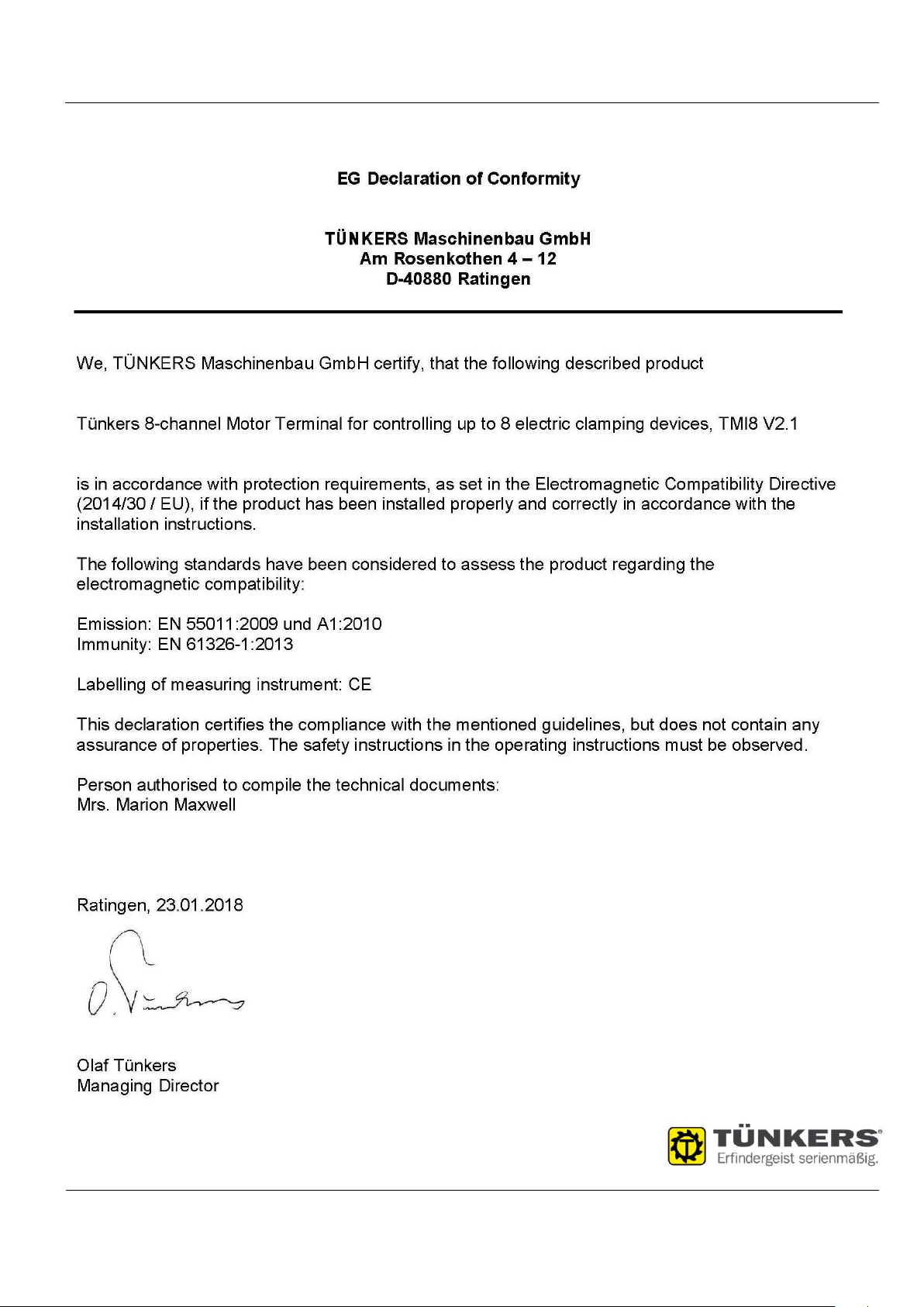
7. EG Declaration of Conformity
Subject to technical alterations Page -12- 06/03/2018
 Loading...