

Page 1
REPAIR
This kind of airplane is far different from the
traditional wood made airplane covered with
covering, it is all plastic includes the fuselage,
wing and tail feathers. Enclosed in the kit, there is
a repair bag includes a super glue, epoxy and ABS
sheets. Use the furnish materials to repair your
plane if there is any damaged. Cut a proper size of
ABS sheet for the crack area as a patch, sand the
glue area with 300-400 grit sand paper first, this
will enhance the adhesion. Patch the crack area or
anywhere need to be reinforced with super glue.
Use epoxy instead of super glue if contacts any
foam inside the wing. Check Thunder Tiger
authorized distributors for customer service or
tech support if any problem is encountered.
MEMO
Assembly Manual
Specifications:
Wing Span: 67.00 (1700mm)
Wing Area: 682 sq.in. (44 sq. dm )
Length: 49.20 (1250mm)
Weight: 6.60 lbs.(3000g)
Engine: .61 2C Req'd
.91 4C Req'd
Radio: 4CH Req'd
2
Warranty
This kit is guaranteed to be free from defects in material and workmanship at the date of purchase.
It does not cover any damage caused by use or modification. The warranty does not extend
beyond the product itself and is limited only to the original cost of the kit. By the act of building this
user-assembled kit, the user accepts all resulting in liability for damage caused by the final
product. If the buyer is not prepared to accept this liability, it can be returned new and unused to
the place of purchase for a refund.
JE6982
116
Page 2
INTRODUCTION
Introduction
Thanks for purchasing the ABS ( ABS is a “polymericed alloy” of the three materials Acrylonitrile,
Butadiene and Styrene) series airplane from Thunder Tiger, this kind of airplane is far different from the
traditional wood made airplane covered with covering. The plane is all plastic includes the fuselage, wing
and tail feathers which are impact and water resistance that we ensure you will have longer enjoy time with
this product.
ITEMS NEEDED
This is not a toy. Assembly and running this product requires adult supervision.
To gain the most from this
airplane kit, it is important that you read the instructions thoroughly and then follow them exactly. This
instruction manual has been written with a novice modelers in mind, but includes many hints and modeling
tips that even experienced modeler can benefit from. We strongly suggest that you read through the
construction sequence and eliminate many questions you might have if you did not read the manual prior to
starting the actual construction.
The first thing you should do before beginning assembly is to check the contents of your kit against the
parts list on pages 4 and 5. If any parts are missing, contact your dealer or authorised Thunder Tiger
Distributors immediately for replacement.
Browse www.thundertiger.com for more information or
customer service if you encounter any problems.
TABLE OF CONTENTS
INTRODUCTION..............................................................................................................2
OTHER ITEMS REQUIRED.......................................................................................2
ITEMS NEEDED.....................................................................................................3
PARTS DRAWING...............................................................................................................4-5
PRE-ASSEMBLE NOTES....................................................................................6
WING..........................................................................................................6-7
FUSELAGE...........................................................................................................8-10
TAIL..........................................................................................................11-12
ENGINE.............................................................................................................12-13
RADIO......................................................................................................14
BALANCE.............................................................................................................................15
PEPAIR.................................................................................................................................16
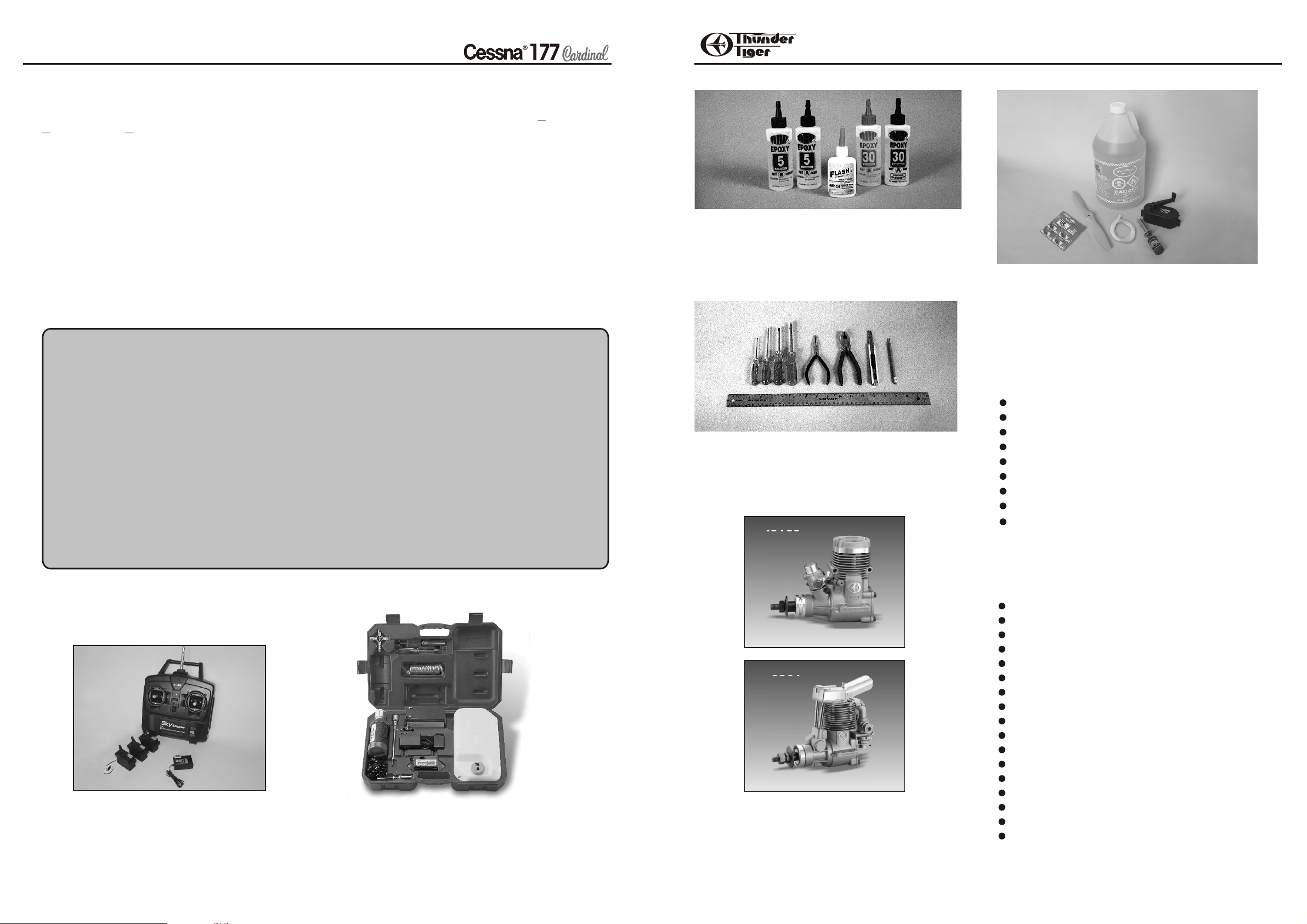
Adhesives- You will need two types of adhesives for the
Cessna 177- Epoxy and Instant ( cyanoacrylate )
adhesives. We recommend that you purchase both 5minute and 30-minute epoxy to cut down on assembly
time, but you can get by with only 30-minute epoxy if time
is no important. You will also need a small bottle of both
"Thick" and "Thin" instant adhesive.
Tools-Model assembly can be much easier if the proper
tools are used. Therefore we have included in our
checklist to above, a complete listing of all the tools we
used to assemble our prototype models. As you will
notice, many household tools can be utilized during
construction.
No.9160
Flight Equipment There are several “support” items
that you will need to purchase in order to get your engine
running and your plane in the air. These are listed at the
bottom.
Flight Equipment Needed Check List
Foam Rubber Padding for the radio
Stick on Lead Strip for balancing the plane
3 or 4 Props (see engine instructions)
10%-15% Glow Fuel
Fuel Pump or Bulb
Electric Starter or “ Chicken Stick”
Glow starter
Extra Glow Plug(s)
Silicon Tubing
ITEMS REQUIRED FOR ASSEMBLY
A checklist is also provided on the next page which
will make shopping for these items easier.
Radio - A 4- channel radio with 4 standard servos is
required. Most lower priced 4-channel radios only
come with three standard servos so you may need to
purchase the fourth servo separately.
ACCESSORIES
No.1263-65
Carry Master-Thunder Tiger offer a complete
organizer of field equipment. All you need is included.
2
No.9801
Engine The Thunder Tiger PRO-61 and F-91S are the
ideal engines for this airplane. These quiet running engines
are easy to start, require no special break in periods, are
very easy to maintain and will last for years.
Comprehensive Items Needed Check List
4-Channel Radio with 4 Standard Servos
5-Minute Epoxy (4 ounces or so)
30-Minute Epoxy (4 ounces or so)
“Thin” Instant Adhesive (1/2 ounce)
“Thick” Instant Adhesive (1/2 ounce)
Hobby Knife and Blades
Epoxy Mixing Sticks and/or Brushes
Sandpaper (150 grit)
Masking Tape
Rubbing Alcohol
Paper Towels
Ruler
90 Degree Triangle
Waxed Paper
Fine-Point, Felt-Tip Pen
Misc. Household Tools
Drill and Bits 2mm,5mm,8mm (5/64", 13/64", 5/16")
3
Page 3
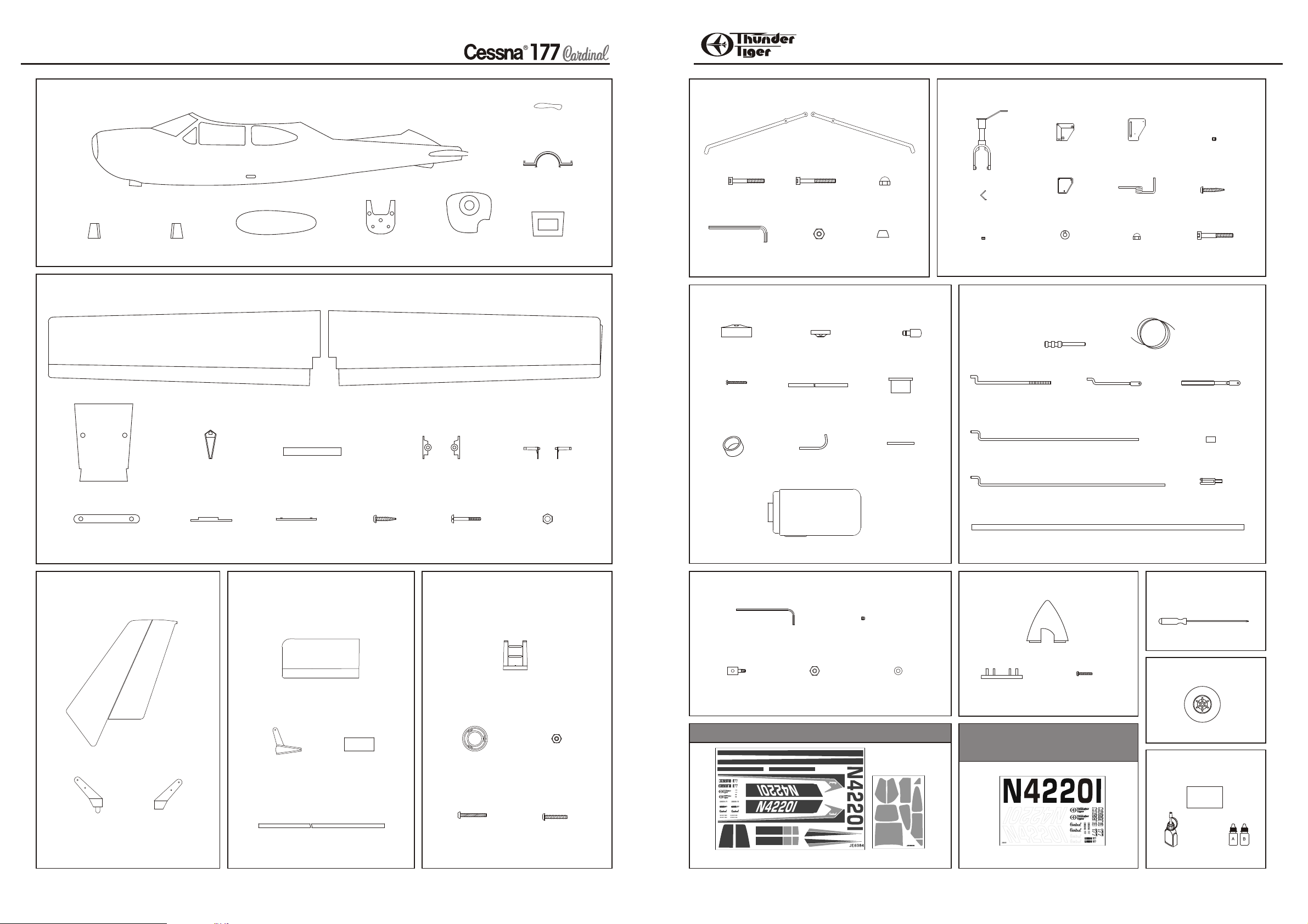
PARTS DRAWINGS
PARTS DRAWINGS
AS6681 Fuselage Set
AS6681-1 (K20)
Nut Support A (1) Nut Support B (1)
AS6682 Main Wing Set
AS6682-1 (K20)
Muffle Fairing (1)
Main Wing (L/1,R/1)
Rubber Band (2)
Fuselage (1)
Centre Bulkhead (1) Servo Tray (1)
Firewall (1)
Fuel Tank Support (1)
AS6686 Main Landing Gear Set
Main Gear
(L/1,R/1)
4X30mm Socket
Screw (3)
Hex Wrench (1)
4X35mm
Screw (2)
M4 Nut (5)
M4
Locknut (2)
M4 Cone (3)
AS6688 400cc Fuel Tank
Cap (1) Back Plate (1)
3x20mm Self
-tapping Screw (1)
Silicon Tube (1)
Rubber Stopper (1)
Clunk (1)
AS6687 Nose Gear Set
Nose Gear
Mount A (1)
Nose Gear (1)
Damper
Linkage(1)
Nose Gear
Spacer(1)
Nose Gear
Back Plate (1)
Wheel
Collar (1)
AS6689 Linkage Set
Threaded Adaptor (2)
Aileron Pushrod (2)
Nose Gear
Mount B (1)
Nose Gear
Wire(1)
M4
Locknut (1)
Z-Bend End
W / Hole (2)
3x3mm
Setscrew (1)
3x25mm
Wood Screw (3)
4X40mm Socket
Screw (1)
Wire 2 (1)M
Threaded End
W / Hole (2)
Aileron End
Cap (2)
Center Sleeve (1)
Wing Joiner (1)
Aileron Servo
Rail U (1)
AS6683 Vertical Tail Set
AS6683-1 (K20)
Rudder (1)
Wood Stick (1)
Aileron Servo
Rail V (1)
3x10mm
Wood Screw (4)
Rod Support (L/1,R/1)
AS6684 Horizontal Tail Set
AS6684-1 (K20)
Horizontal Tail (2)
Elevator
Control Horn (1)
Foam Block (1)
Connecting
Rod (L/1,R/1)
Wing Bolt (2)
M7 Hex Nut (2)
AS6685
Engine Mount Set
Engine Mount (1)
Engine Mount
Back Plate(1)
Hex Nut (3)
Bent Brass Tube (2) Brass Tube (1)Silicon Ring (1)
Fuel Tank (1)
3169 EZ Connector Set AS6675
3282W Spinner
Nose Gear Pushrod (1)
Throttle Pushrod (1)
CFK Pushrod (1)
Brass Tube (4)
Screw Driver
Hex Wrench (1)
3x3mm
Setscrew (2)
Spinner (1)
Screw Driver (1)
3297 Wheel
Pushrod
Retainer (2)
AS6690 Decal
M2 Washer (2) M2 Nut (2)
(Only comes with 4595-K10)
Backplate (1)
AS6691 Decal
(Only comes with 4595-K20)
3x12mm Self
-tapping Screw (2)
Wheel (3)
AS6680
Repair Bag
Clevis (6)
Rudder Control
Horn A (1)
Rudder Control
Horn B (1)
Elevator Spar (1)
4
4x25mm
Screw (3)
4x24mm Self
-tapping Screw (4)
Decal (1)
ABS(2)
Decal (1)
CA Glue(1)
Epoxy(1)
5
Page 4

PREASSEMBLY
PRE-ASSEMBLY NOTES
1. If you are not an experienced pilot, plan to have a fully
competent pilot check your completed model and help
you with your first flights. Even though we have tried to
provide you with a very thorough instruction manual,
models are rather complicated and an experienced
modeler can quickly check over your model to make sure
your first flights are successful.
2. Please assemble your model exactly according to these
instructions . Do not attempt to modify or change the
Cessna 177 in any way as doing so may adversely change
its flying characteristics.
3. Before you begin, please check the entire contents of
this kit against the parts drawing make sure that no parts
are missing or damaged. This will also help you to
become familiar with each component of your plane. If
you find that any of the parts are either missing or
damaged, please contact your dealer immediately for
replacement.
Note: Your dealer cannot accept kits for return if
construction has begun.
4. Trial fit each part before gluing it in place. Make sure
you are using the correct part and that it fits well before
assembling. No amount of glue can make up for a poor
fitting part.
2.Trail fit the wing joiner, make sure it is level with
the wing surface. Next apply enough epoxy to
joiner and wing slot cut. Epoxy this wing joiner in
place with the wood stick under two wing halves,
this is for correct “ Dihedral” of the main wing.
5.Sand the wing center area where is going to glue
the Centre Sleeve. This is to enhance the
adhesion.
WING
8.Secure the aileron servo in place. Next thread
the clevis onto the aileron pushrod, insert the Zbend end to the aileron control horn then snap on
the clevis to the servo horn as shown.
Suggest to install two servos and set up the
“FLAPRON”, this will help the landing slower.
WING ASSEMBLY
1.Locate the wing parts as shown, you may refer to
the parts drawing of main wing set in page 4.
3.Locate two Aileron End Caps, then CA them in
place. Drill the wing bolt hole through the wing with
8mm drill bit.
4.Temporally install the Centre Sleeve, mark the
guide lines on both wing surface when it centered.
6.Glue the Centre Sleeve in place with epoxy or
thick CA. Next install the aileron Connecting Rod
and Rod Support. Make sure leave 1mm between
the control horn and support bearing.
U
V
7.Locate the Aileron Servo Rails, note the servo
rail will have to accommodate to your servo size
before you secure on the aileron servo well. Also
make sure the Rails are at right positions.
9.Drill 2mm holes for the rudder pull-pull wire as
photo shown.
10.Drill 5mm inlet hole as photo indicated.
6
7
Page 5

FUSELAGE
FUSELAGE
4mm
3mm
10mm
11. Using a 4mm drill bit to drill through the front
bulkhead for the engine mounting screws. Drill
3mm holes for the nose leg mounting holes on the
firewall. Drill 10mm hole for the steering pushrod
as photo shown.
12.Glue the Engine Mount and Nose Gear Back
Plates in the firewall, make sure the holes are
aligned. Fit the 4mm nuts into the Engine Mount
Back Plate.
14.Drill three 4mm holes in the positions of centre
bulkhead.
15.Place the cones in the position of centre
bulkhead and CA them in place. Insert the M7 nuts
in the nut support.
17.Both sand the glue area on bulkhead and
fuselage. Trail fit the assembled bulkhead into the
position as photo shown. You may use the
furnished screw driver thread through the fuselage
and bulkhead is against the screw driver. Note the
screw driver should move forward to the very end.
CA the bulkhead in place firmly.
A
18. Locate the Main Landing Gear and mounting
screws as shown.
B
20. Trail fit the servo in the servo tray, trim the
servo tray if it is necessary. Next trail fit the servo
tray into fuselage and slide into the position
locking the front of the tray into the recess of the
central bulkhead. Remove the servo tray and
slightly sand the glue area then CA the servo trail
in place.
21.Locate the engine mount then secure the
engine mount in place with three 4x25mm screws.
13.Insert the firewall through the center opening of
the fuselage and place in right position. You may
need to push the firewall forward to the place until
it fits correctly in the formed recess.
16.Glue the support to the bulkhead and insert the
M4 nuts in the cones.
4x30mm
A
4x35mm
19.Insert the legs through the fuselage and place
on the bulkhead then secure the main gear firmly
with two 4x35mm screws and one 4x30mm socket
screw.
B
22.Locate the nose gear accessories and 3x25mm
wood screws as shown.
98
Page 6

TAI LFUSELAGE
23.Sandwich the Nose Gear Wire with the Nose
Gear Mount, then secure mount firmly in place
with three 3x25mm wood screws.
24.Install the wheel on the main gear with 4x30mm
socket screw one M4 nut and one M4 locknut. Do
the same on the other side.
26.Assemble the scale nose gear, make sure
wheel could rotate freely. CA the Damper Linkage
on the Scale Nose Gear. Next thread the Z-bend
end to the steering arm.
27.Thread the nose gear pushrod into the fuselage
then install the scale nose gear onto the nose gear
wire the secure it in place with collar and 3x3mm
setscrew.
29. Make mark at the center of the tail spar as
shown.
31.When epoxy has cured, repeat the operation
with the other tail half with the addition of more
epoxy on the roots of the tail to glue two halves
together. You may use mask tape to hold two
halves together until it cures. Make sure two
halves are aligned accurately. CA the Elevator
Control Horn in place firmly as shown.
32.You may use file to enlarge the elevator
pushrod exit hole so clevis will not contact the
fuselage. Also trim the fuselage end as shown so
horizontal tail can go in.
25.Locate the scale nose gear accessories as
shown. Thread the clevis onto the pushrod.
28.Locate the horizontal tail halves then use
hobby knife carefully trim away the molded cap at
the root of the tail halves for the elevator spar.
10
30.Pay Attention to the Spar Installation: Apply a
generous coat of epoxy to the narrow edges of the
spare on one side only of the halfway point. Hold
the spare horizontally so the epoxied edges face
to the leading and trailing edges of the tail, then
insert it in the tail up to the marked point( step 1).
When arrive the marked point then carefully rotate
the spar (step 2). Place the tail half leading edge
down on flat surface and support the extended
part of the Foam Block(step 3). Move it back and
forth for about 5mm two or three times to even
distribute the epoxy(step 4).
33.Temporarily install main wing in place with the
two Wing Bolts. Trail fit the tail in place and check
the alignment with the wing and fuselage. The tail
should be parallel to the wing when looking forward
from the rear and top of the model. When satisfied,
make mark on the tail along the fuselage. Remove
the tail and slightly sand the glue area then CA tail
in place.
11
Page 7

ENGINE
34.Locate the Vertical Fin and Rudder Control
Horns, cut away the molding caps on the base of
the fin. This is for pushrod can go through.
37.Locate the spinner , engine prop nut, washer
and prepare a suitable propeller for your engine.
40.Locate the throttle pushrod and engine
mounting screws. Connect the throttle pushrod to
the throttle lever.
ENGINE
43.Secure the engine on the engine mount firmly
with the furnished mounting screws.
35.Fit the two rudder control horns to the rudder,
pushing them firmly together. CA each control horn
around the base in place. Pour a few drops of
epoxy into indicated hole.
1mm
38.Temporarily fit the engine to the engine mount
and install the propeller and spinner being used.
Slide the engine on the mount until there is about
1mm (1/16”) gap between the back plate and the
front of fuselage. Make mark of the engine
mounting holes. It may need to trim the engine
opening to fit your engine.
44.Use the muffler hole as the guide to drill a hole
on the cowl. Enlarge the hole up to 6mm in
diameter so you can thread the muffler bolt in.
41.Thread the pushrod through the firewall.
36.Insert the fin into the fuselage before the epoxy
cures, make sure the fin sits vertically to the
horizontal tail. CA the fin to the fuselage firmly.
39.Remove the engine and mount from the
fuselage. Drill 3.6mm hole( 9/64”) on the marks
for 4x20mm self tapping screws.
12
42.Next place engine on the engine mount. Trail
to move the pushrod back and forth to make sure
the throttle lever moves smoothly. Bend the
pushrod if necessary.
45.Secure the muffler tightly with the muffler bolts
that come with your engine.
13
Page 8

RADIO
GLASS FILLED NYLON CLAMP PLATE
RUBBER BUNG
GLASS FILLED NYLON CAP
BRASS SCREW
BRASS NUT
BRASS BENT FILLER TUBE
SILICON TUBE
BRASS FEED TUBE
BALANCE
CLUNK
46.If a 4 stroke engine is used , then glue the
Fairing to the muffler well. The pushrod hole on
the firewall may need to drill to accommodate to
your 4 stroke engine throttle lever.
47.Install the servo in place, you will need to install
EZ connectors on the servo horns for rudder servo
and throttle servo( both suggested on the second
hole).
49.Locate the Threaded End w/hole, thread it into
the Clevis at least 6mm, then loop the other end of
cable as you did on Z-Bend End. Snap on the
clevis to the rudder control horn then adjust the
tension. Make sure both cables are equal then
clamp the brass tube. You can adjust the tension
slightly by threading in the clevis.
50. Firstly trim the CFK Pushrod in length of
690mm( 27-5/32”),next locate the Threaded
Adaptor, slightly sand the glue area of adaptor to
make sure there is no oil on it. Apply enough epoxy
to glue the adaptors in the CFK Pushrod at two
ends as shown. Thread the clevises on the
adaptor after epoxy has cured. Apply a silicon ring
to the clevis.
5 TO 10 MM
52.Assemble the tank as figure; install the silicon
rubber ring on the tank and insert the tank in the
opening of the firewall. Insert the Tank Support
and attach it under the fuel tank. You may use
rubber band to hold the tank on support. Next glue
the support inside the fuselage with CA.
53.Finally install the propeller and spinner, note
the propeller must be secured against the pin on
the spinner back plate. Always adjust the
propeller at a good starting angle.
55.Connect the fuel tube properly to the muffler
and carburetor.
BALANCE
3”(75~80mm)
CONTROL THROWS
Make sure the direction of servo moves correctly. If not
switch the reversing switch on the transmitter. If the
control surface does not move far enough, either move
the pushrod out farther on the servo horn or move the
clevis in farther on the control horn. If the control
surface moves too much, either move the pushrod in on
the servo horn or move the clevis out farther on the
control horn. Adjust the control throws as the initial
setting as follows:
48.Cut the cable into two pieces. Next drill a small
hole in the fairing at the rear top of fuselage.
Thread the cable from the hole through the
fuselage to the servo tray. Use a piece of tape to
fix the cable at the fairing from loosening. Now
loop the Z-Bend End first.( first thread the brass
tube, next thread the Z-bend end, go back to the
brass tube again. Adjust the distance between the
Z-bend end and the tube then thread the cable
through the brass tube again and make a circle as
small as possible. Clamp the brass tube with pliers
to lock the cable from loosening. Insert the Z-Bend
Ends to the rudder servo horn at the outmost holes.
Note: make sure two cables are cross each other.
51.Thread the CFK pushrod through the fuselage
and snap on the control horn. Adjust the silicon
ring to keep clevis from loosening. Snap on the
other end to servo horn when elevator and servo
are both in neutral position. Adjust clevis if
necessary.
Thread the Throttle pushrod and Steering pushrod
through the EZ Connectors. Adjust the pushrod
when they are in neutral position.
14
54.Secure the spinner with 3x12mm self-tapping
screws.
15
Aileron
Elevator
Rudder
1/2",12mm
1/2",12mm
5/8”,15mm
5/8”,15mm
1",25mm
1",25mm
 Loading...