

Tuncmatik NEWTECH PRO User Manual

info@tuncmatik.com / www.tuncmatik.com
NEWTECH PRO
10-20 KVA (3/1) ONLINE
UNINTERRUPTIBLE POWER SUPPLY
USER MANUAL

1

2
Please comply with all warnings and operating
instructions in this manual strictly. Save this
manual properly and read carefully the following
instructions before installing the unit. Do not
operate this unit before reading through all
safety information and operating instructions
carefully.

3
Table of Contents
1. SAFETY AND EMC INSTRUCTIONS ................................................................................................. 4
1-1. TRANSPORTATION AND STORAGE ............................................................................................................... 4
1-2. PREPARATION ....................................................................................................................................... 4
1-3. INSTALLATION ...................................................................................................................................... 4
1-4. OPERATION ......................................................................................................................................... 5
1-5. STANDARDS ......................................................................................................................................... 5
2. INSTALLATION AND OPERATION .................................................................................................. 6
2-1. UNPACKING AND INSPECTION ................................................................................................................... 6
2-2. REAR PANEL VIEW................................................................................................................................. 6
2-3. SINGLE UPS INSTALLATION ..................................................................................................................... 8
2-4. UPS INSTALLATION FOR PARALLEL SYSTEM ................................................................................................ 11
2-5. SOFTWARE INSTALLATION ..................................................................................................................... 12
3. OPERATIONS ................................................................................................................................ 13
3-1. BUTTON OPERATION ............................................................................................................................ 13
3-2. LED INDICATORS AND LCD PANEL .......................................................................................................... 13
3-3. AUDIBLE ALARM.................................................................................................................................. 15
3-4. SINGLE UPS OPERATION ...................................................................................................................... 16
3-5. PARALLEL OPERATION .......................................................................................................................... 18
3-6. ABBREVIATION MEANING IN LCD DISPLAY ................................................................................................. 19
3-7. LCD SETTING .................................................................................................................................... 20
3-8. OPERATING MODE/STATUS DESCRIPTION ................................................................................................. 25
3-9. FAULT CODE ...................................................................................................................................... 29
3-10. WARNING INDICATOR ........................................................................................................................ 30
3-11 WARNING CODE ................................................................................................................................. 30
4. TROUBLE SHOOTING ................................................................................................................... 31
5. STORAGE AND MAINTENANCE ..................................................................................................... 32
5-1. STORAGE .......................................................................................................................................... 32
5-2. MAINTENANCE .................................................................................................................................... 32
6. SPECIFICATIONS ......................................................................................................................... 33
4
1. Safety and EMC instructions
Please read carefully the following user manual and the safety instructions before installing the unit or using
the unit!
1-1. Transportation and Storage
Please transport the UPS system only in the original package to protect against shock and
impact.
The UPS must be stored in the room where it is ventilated and dry.
1-2. Preparation
Condensation may occur if the UPS system is moved directly from cold to warm environment.
The UPS system must be absolutely dry before being installed. Please allow at least two hours for the
UPS system to acclimate the environment.
Do not install the UPS system near water or in moist environments.
Do not install the UPS system where it would be exposed to direct sunlight or nearby heater.
Do not block ventilation holes in the UPS housing.
1-3. Installation
Do not connect appliances or devices which would overload the UPS (e.g. big motor-type
equipment)) to the UPS output sockets or terminal.
Place cables in such a way that no one can step on or trip over them.
Do not block air vents in the housing of UPS. The UPS must be installed in a location with good
ventilation. Ensure enough space on each side for ventilation.
UPS has provided earthed terminal, in the final installed system configuration, equipotential
earth bonding to the external UPS battery cabinets.
The UPS can be installed only by qualified maintenance personnel.
An appropriate disconnect device as short-circuit backup protection should be provided in the
building wiring installation.
An integral single emergency switching device which prevents further supply to the load by the
UPS in any mode of operation should be provided in the building wiring installation.
Connect the earth before connecting to the building wiring terminal.
Installation and Wiring must be performed in accordance with the local electrical laws and
regulations.
5
1-4. Operation
Do not disconnect the earth conductor cable on the UPS or the building wiring terminals in any
time since this would cancel the protective earth of the UPS system and of all connected loads.
The UPS system features its own, internal current source (batteries). The UPS output sockets or
output terminal blocks may be electrically live even if the UPS system is not connected to the building
wiring outlet.
In order to fully disconnect the UPS system, first press the “OFF” button and then disconnect the
mains.
Ensure that no liquid or other foreign objects can enter into the UPS system.
The UPS can be operated by any individuals with no previous experience.
1-5. Standards
* Safety
IEC/EN 62040-1-1
* EMI
Conducted Emission...............................:IEC/EN 62040-2
Category C3
Radiated Emission..................................:IEC/EN 62040-2
Category C3
*EMS
ESD.........................................................:IEC/EN 61000-4-2
Level 4
RS........................................................ ...:IEC/EN 61000-4-3
Level 3
EFT......................................................... :IEC/EN 61000-4-4
Level 4
SURGE................................................... :IEC/EN 61000-4-5
Level 4
CS........................................................... :IEC/EN 61000-4-6
Level 3
Power-frequency Magnetic field.............. :IEC/EN 61000-4-8
Level 3
Low Frequency Signals............................:IEC/EN 61000-2-2
Warning: This is a product for commercial and industrial application in the
second environment-installation restrictions or additional measures may be
needed to prevent disturbances.
6
2. Installation and Operation
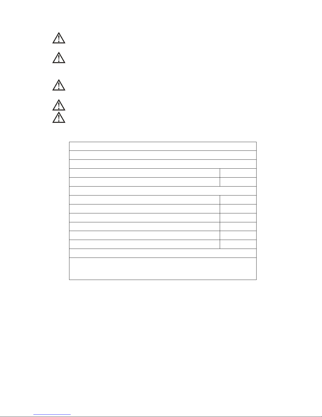
There are two different types of online UPS: standard and long-run models. Please refer to the following
model table.
Model
Type
Model
Type
10K
Standard
model
10KL
Long-run
model
15K
15KL
20K
20KL
We also offer optional parallel function for these two types by request. The UPS with parallel function is
called as “Parallel model”. We have described detailed installation and operation of Parallel Model in the
following chapter.
2-1. Unpacking and Inspection
Unpack the package and check the package contents. The shipping package contains:
● One UPS
● One user manual
● One monitoring software CD
● One RS-232 cable (option)
● One USB cable
● One parallel cable (only available for parallel model)
● One share current cable (only available for parallel model)
● One battery cable (only available for 10KL)
NOTE: Before installation, please inspect the unit. Be sure that nothing inside the package is damaged
during transportation. Do not turn on the unit and notify the carrier and dealer immediately if there is any
damage or lacking of some parts. Please keep the original package in a safe place for future use.
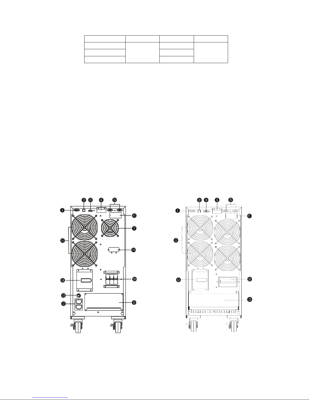
2-2. Rear Panel View
Diagram1: 10K/10KL Rear Panel Diagram 2: 15KL/20KL Rear Panel

7
Diagram 3: 15K/20K Rear Panel Diagram5 :15KL/20KL Input/Output
Terminal
Diagram 6: 15K/20K Input/Output Terminal Diagram 7:15K/20K Grounding
Terminal
Diagram 4: 10K/10KL Input/Output
Terminal

8
1. RS-232 communication port
2. USB communication port
3. Emergency power off function connector (EPO connector)
4. Share current port (only available for parallel model)
5. Parallel port (only available for parallel model)
6. Intelligent slot
7. Charger fan
8. Power stage fan
9. Maintenance bypass switch
10. Input circuit breaker
11. Output circuit breaker for receptacles
12. Output receptacles: connect to mission-critical loads
13. Input/Output terminal (Refer to Diagram 4、5、6 and 7 for the details)
14. Output terminal: connect to mission-critical loads
15. Programmable output terminal: connect to non-critical loads
16. External battery terminal (only available for Long-run model)
17. Utility input terminal
18. Grounding terminal
2-3. Single UPS Installation
Installation and wiring must be performed in accordance with the local electric laws/regulations and execute
the following instructions by professional personnel.
1) Make sure the mains wire and breakers in the building are enough for the rated capacity of UPS to
avoid the hazards of electric shock or fire.
NOTE: Do not use the wall receptacle as the input power source for the UPS, as its rated current is less than
the UPS’s maximum input current. Otherwise the receptacle may be burned and destroyed.
2) Switch off the mains switch in the building before installation.
3) Turn off all the connected devices before connecting to the UPS.
4) Prepare wires based on the following table:
Model
Wiring spec (AWG)
Input
Output
Battery
Ground
10K 8 8 8
10KL 8 8 8 8
15K 6 6 6
15KL 6 6 6 6
20K 6 6 6
20KL 6 6 6 6
NOTE 1: The cable for 10K/10KL should be able to withstand over 63A current. It is recommended to
use 8AWG or thicker wire for safety and efficiency.
NOTE 2: The cable for 15K/15KL should be able to withstand over 75A current. It is recommended to
use 6AWG or thicker wire for safety and efficiency.
NOTE 3: The cable for 20K/20KL should be able to withstand over 100A current. It is recommended to
9
use 6AWG or thicker wire for safety and efficiency.
NOTE 4: The selections for color of wires should be followed by the local electrical laws and
regulations.
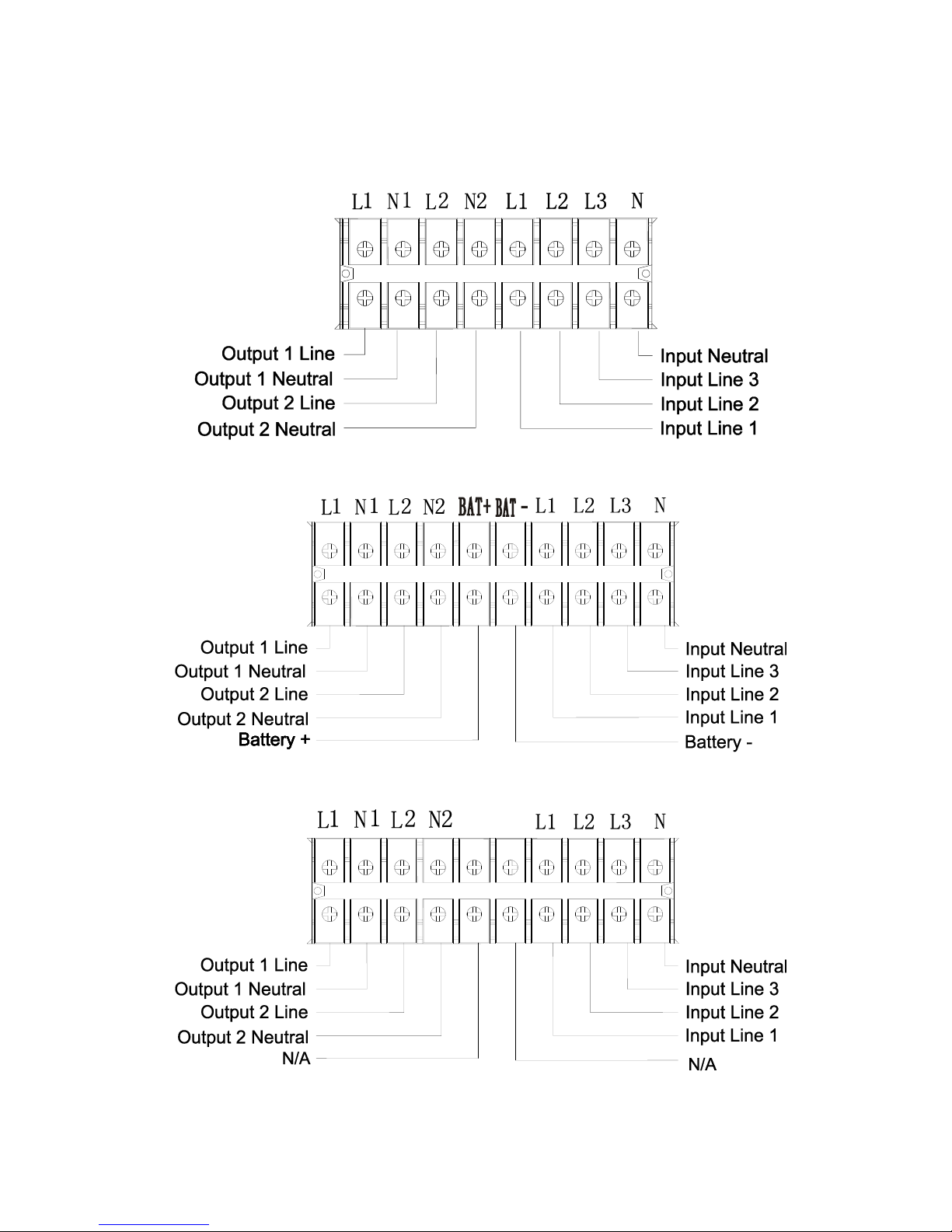
5) Remove the terminal block cover on the rear panel of UPS. Then connect the wires according to the
following terminal block diagrams: (Connect the earth wire first when making wire connection. Disconnect
the earth wire last when making wire disconnection!)
Terminal Block wiring diagram of 10K/10KL
Terminal Block wiring diagram of 15KL/20KL
Terminal Block wiring diagram of 15K/20K

10
NOTE 1: Make sure that the wires are connected tightly with the terminals.
NOTE 2: There are two kinds of outputs: output terminal/outlets and programmable terminal. Please
connect non-critical devices to the programmable terminal and critical devices to the output terminal/outlets.
During power failure, you may extend the backup time to critical devices by setting shorter backup time for
non-critical devices.
NOTE 3: Please install the output breaker between the output terminal and the load, and the breaker
should be qualified with leakage current protective function if necessary.
6) Put the terminal block cover back to the rear panel of the UPS.
Warning: (Only for standard model)
● Make sure the UPS is not turned on before installation. The UPS should not be turned on during wiring
connection.
● Do not try to modify the standard model to the long-run model. Particularly, do not try to connect the
standard internal battery to the external battery. The battery type and voltage may be different. If you
connect them together, it maybe causes the hazard of electric shock or fire!
Warning: (Only for long-run model)
● Make sure a DC breaker or other protection device between UPS and external battery pack is installed. If
not, please install it carefully. Switch off the battery breaker before installation.
NOTE: Set the battery pack breaker in “OFF” position and then install the battery pack.
● Pay highly attention to the rated battery voltage marked on the rear panel. If you want to change the
numbers of the battery pack, please make sure you modify the setting simultaneously. The connection
with wrong battery voltage may cause permanent damage of the UPS. Make sure the voltage of the
battery pack is correct.
● Pay highly attention to the polarity marking on external battery terminal block, and make sure the
correct battery polarity is connected. Wrong connection may cause permanent damage of the UPS.
● Make sure the protective earth ground wiring is correct. The wire current spec, color, position,
connection and conductance reliability should be checked carefully.
● Make sure the utility input & output wiring is correct. The wire current spec, color, position, connection
and conductance reliability should be checked carefully. Make sure the L/N site is correct, not reverse
and short-circuited.
 Loading...