

Page 1
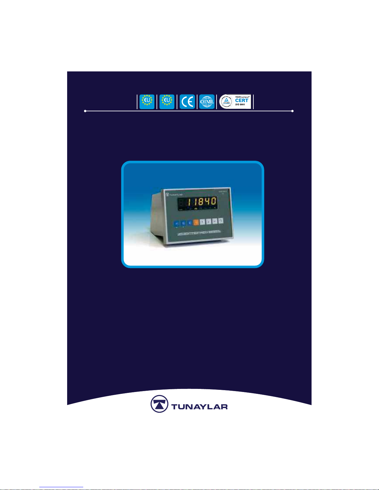
TYPE APPROVAL
90 / 384 / EEC
TYPE TEST
OIML R76/EN45501
Load Line 2
Weight Indicator
User Manuel
Page 2
Page 3
Page 4
Page 5
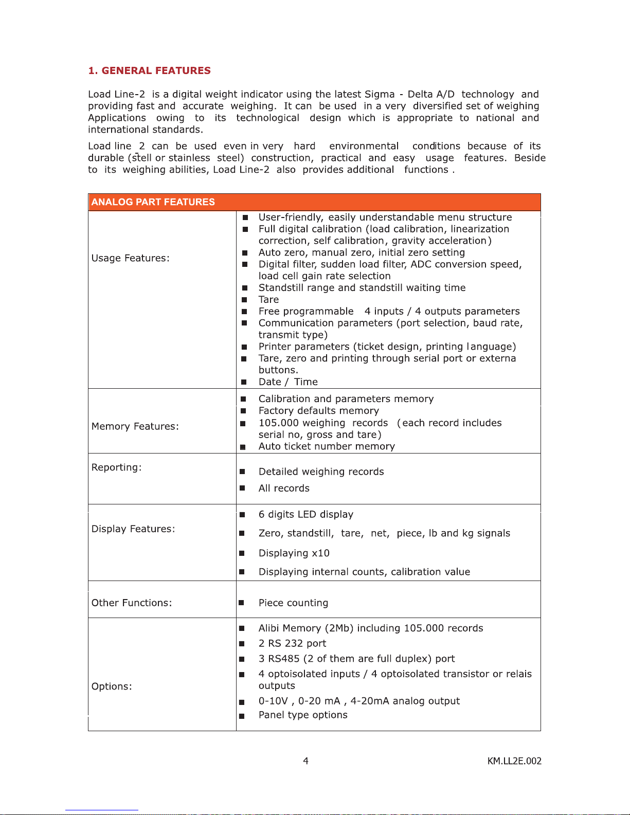
Page 6
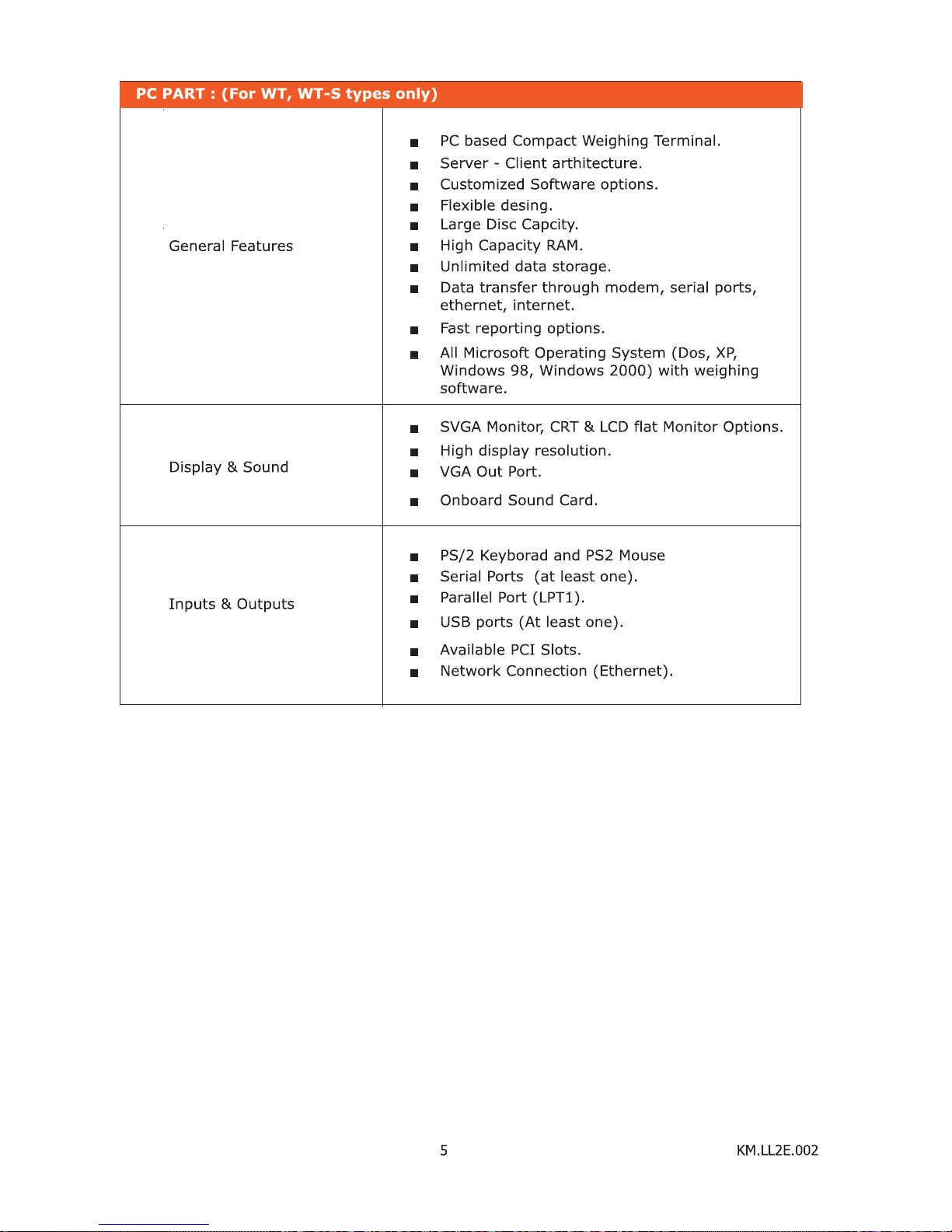
Page 7
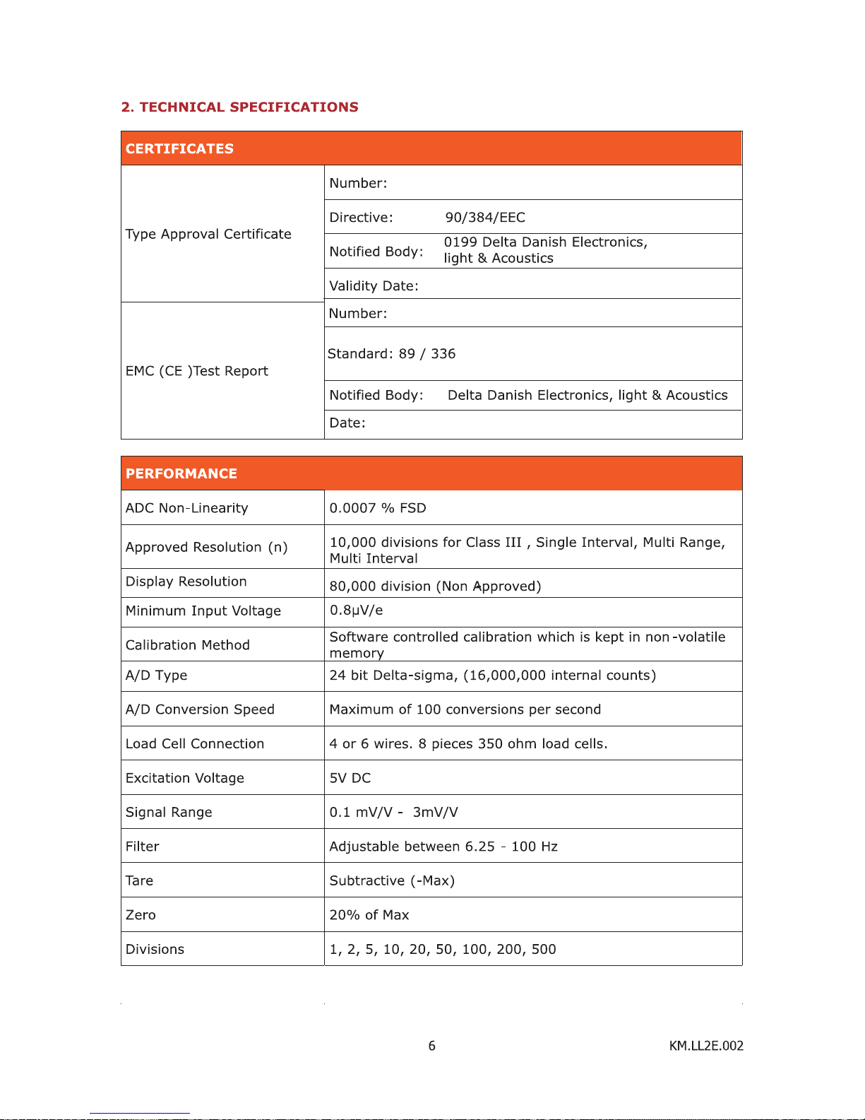
Page 8
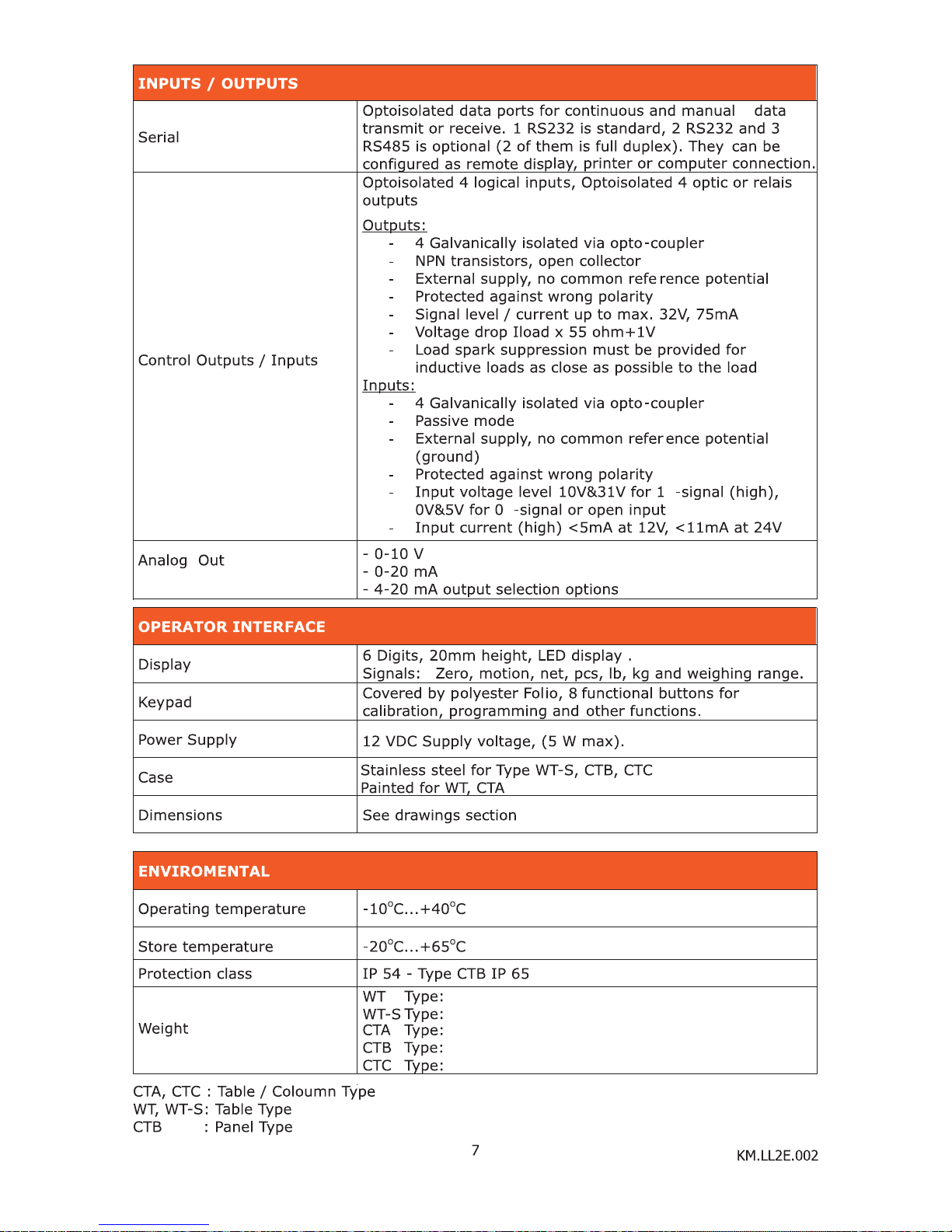
Page 9

3. SUBJECTS TO BE CONSIDERED DURING SETUP, OPERATING AND
MAINTENANCE
Mounting:
The instrument is suitable for table or panel mounting (see
drawings for details of different types). Please observe the
Required environmental conditions as given in technical
Specifications.
Dismantling the Instrument:
When removing the housing, covers or other protecting parts, live
parts or terminals will be exposed. Therefore setting -
up the
instrument must be performed only by trained personnel who are
aware of risks.
Earthing:
The instrument has to be earthed according to latest safety
requlations which are valid locally.
Electrostatically Sensitive Components:
This instrument con tains electrostatically sensitive components.
Therefore repair of electrostatically sensitive assemblies or
Components must be carried out only by qualified personnel at
workstations protected against electrostatic discharge.
Other Instructions:
* Check network voltage and especially protective earthing line before operating the
terminal
* Do not turn on The indicator before load cell cable connector is connected.
* Do not Disconnect
load cell or serial port connectors while the indicator is operating,
* In order to
operate
the indicator properly, it must be connected to a socket which
have earthing,
* Prevent device from direct sunshine. Keep it away from heat sources (like stove),
* Do not make hard push to the buttons on the keypad, do not use pencil,
screwdriver or other sharp tools,
* You can use little moist, soft and hairless gland in order to clean the device,
* Prevent the device from water leaps. If water or any other liguid is spilled on the
device, disconnect all of electricity connections and dry it. After being sure that the
device is dried, you can start to operate it again.
* Check the contents of the consignment for completeness and note whether any
damage has occurred during transport. If the contents are incomplete, or if there is
damage, immediately inform us in order to facilitate the repair or replacement of
the instrument.
!
8
KM.LL2E.002
Page 10

9
Parts provided with your device are as follows:
Additional for WT, WT-S Type :
- PC Monitor
- PC Keyboard
- Mouse
- Load line 2- digital weight display (device itself)
- Adaptor
- MIC 6 Connector (for Load cell)
- User Manual
KM.LL2E.002
Page 11
Page 12

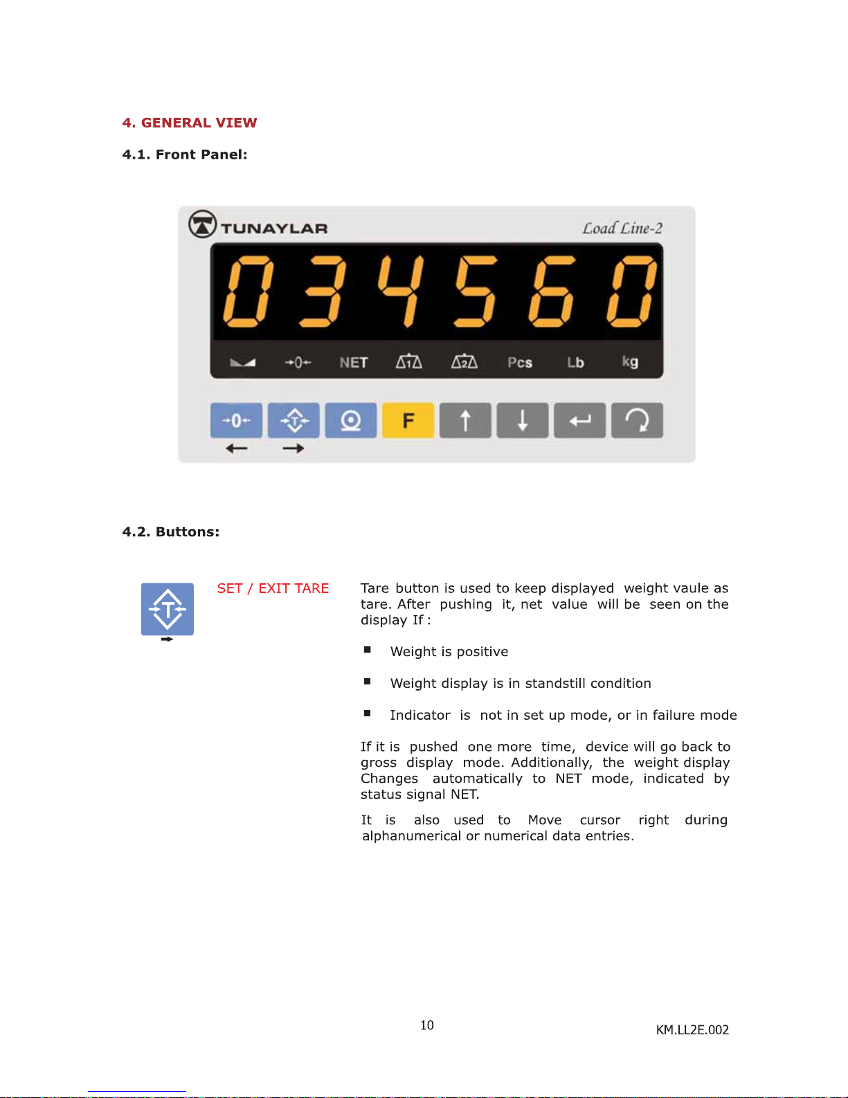
FUNCTION
UPWARD
DOWNWARD
F button is used to enter functions, Calibration and Set Up Menus.
It is used for strolling Upward Direction between
progamming and calibration menus.
It is used for strolling Downward Direction between
progamming band calibration menus.
SET TO ZERO Zero button is used to make displayed weight value
zero. In order to set weight to zero conditions given
Below must be satisfied:
§ Weight display is in standstill condition
§ Tare is reset
§ Gross weight is in previously selected manual zero
range
§ Indicator is not in set up mode, or in failure mode
It is also used to move cursor left during
alphanumerical or numerical data entries.
PRINT Print button is used to print Weig
hing result
Or save it
Into alibi memory. (
This button is disabled if
continuous data transmit mode is active, please see
the section for serial communication. Pressing to this
button causes to print provided that:
§ Indicator' s manual transmit has correspondingly be
activated
§ The weight display is in standstill condition
§ Weight vaule is greater than min printable amount
selected before not in set up mode, or in failure
mode.
11
F
0
KM.LL2E.002
Page 13
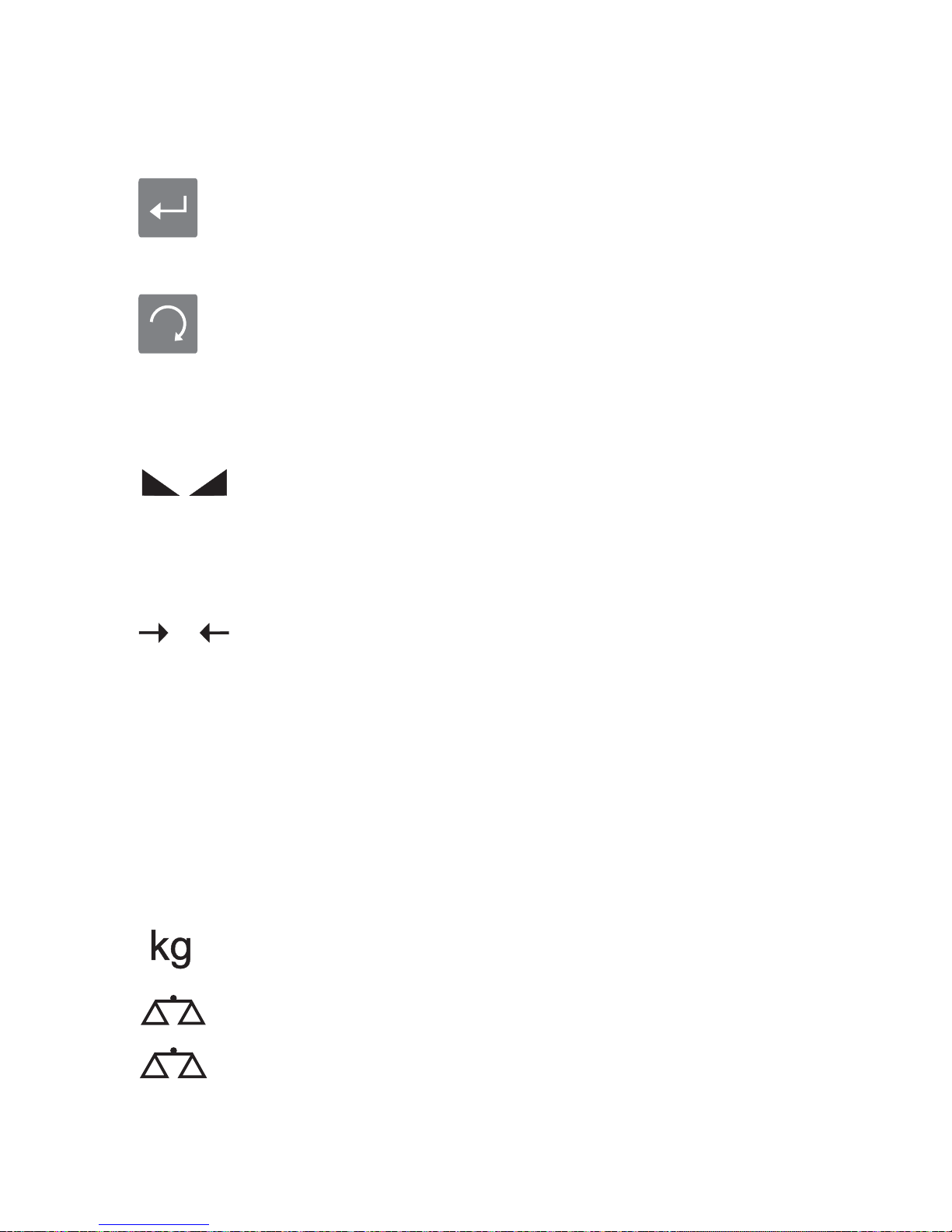
ENTER Enter button is used to enter programming and
calibration menus and to make selection
among
alternatives. It is also used as
“Yes”
button
for
question messages.
ESC Esc button is used to go back to upper menus from
sub menu
s
. It can be used
to exit without changing
parameters. It is also used as cancel button for
question messages.
4.3. Status Signals:
STANDSTILL Standstill signal shows that the load on the
platform
does not move . It lights up as soon as “no motion” is
anymore detected within the initially set range and
time ( If the difference between consecutive weight
values is smaller than the value selected in P2.7, then
this signal will light after the time selected at P2.8
is
elapsed).
ZERO Zero signal shows that there is no load on the scale. It
lights as soon as the actual gross weight is equal to
zero.
NET Net signal will light during net weight value is seen on
display (lights up as soon as having tared by pressing
tare or preset tare button).
PIECES Pieces counting signal
will light if
pices counting
function
is activated
.
12
NET
0
Pcs
POUND Lb signal will light if “ pound” is selected as weighing
unit.
KG
Range 1
Range 2
Kg signal will light if “kilogram” is selected as
This symbol shows 1st weighing range. If the weight is smaller
than Max1 value, it will light.
This symbol shows 2st weighing range. If the weight is greater
than Max1 value, it will light.
weighing
unit
.
Lb
KM.LL2E.002
2
1
Page 14
5. CONFIGURATION AND CALIBRATION MENUS
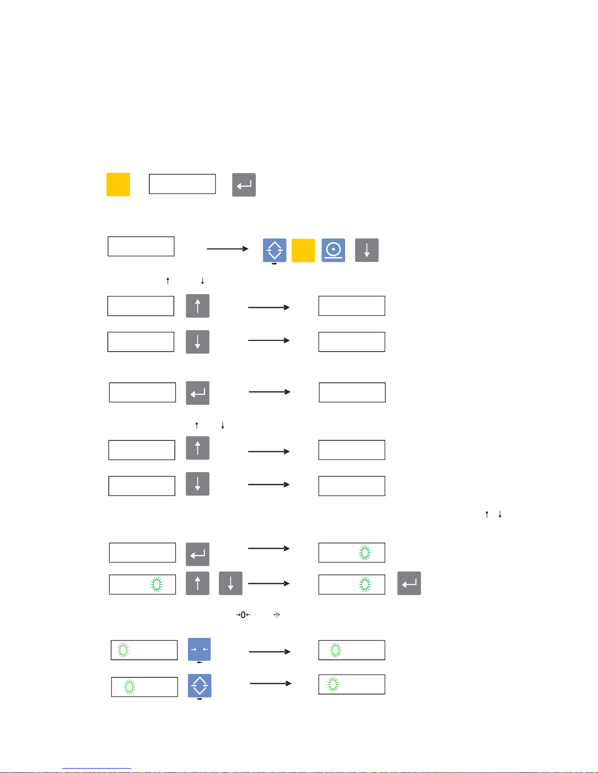
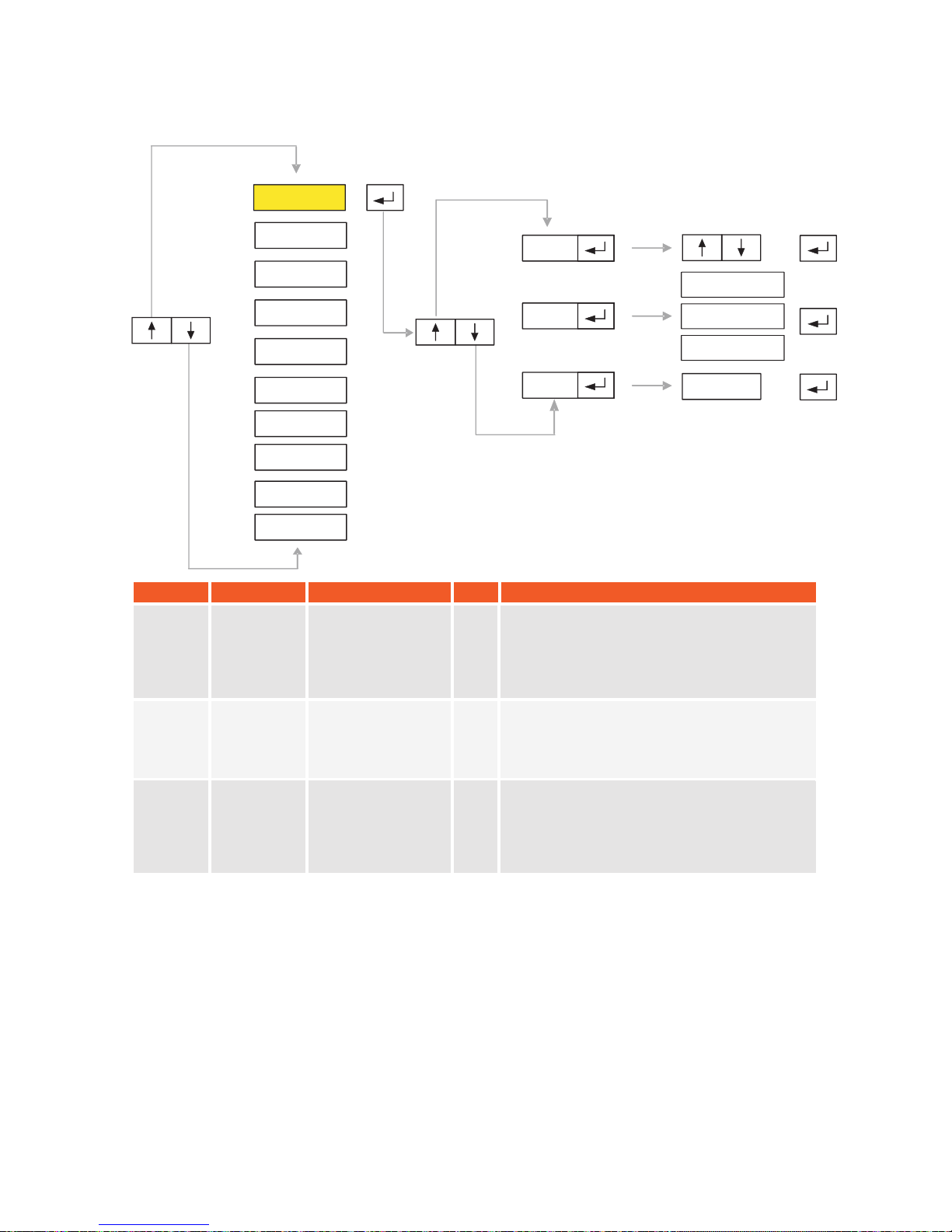
· In order to enter P1-General, P2-Parameters, P3-Configuration and P4-Calibration
menus, calibration jumper must be closed.
· Press F button to enter configuration and calibration
menu
s, when FUNC
?
message
is appeared, press Enter button,
· After PASS ? message is displayed,
(1) (3) (2) (5) (Order of keys starting from zero)
write password and press Enter ,
· You can use and
buttons in order to stroll between main menus
up or down
,
· Use Enter button in order to enter sub menus of any of the main menus,
· Again you can use and buttons in order to stroll between sub menus,
· Press Enter button in order to start changing a parameter. Change it by using
/
buttons and save it by pressing Enter button,
· During data entry menus, and buttons are used to move cursor one step right
or
left
.
P1.0
P1.1
FUNC ?
PASS
P1.1
P1.0
P1-GEN P1.0 1
P1-GEN
P2-PAR
P2-PAR P1-GEN
P1.0 1
P1.0
1
1
P1.0
P1.0 0
0 00000
0 0 0000
0 0 0000
0 00000
13
F
F
T
T
0
KM.LL2E.002
Page 15
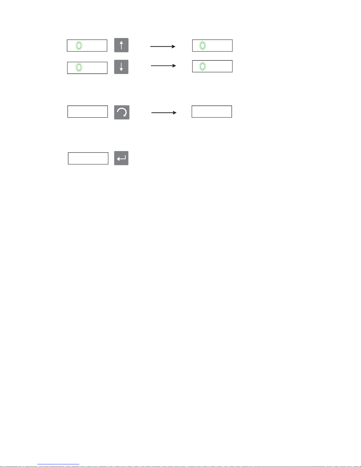
· After changes are confirmed by enter button u,se Esc button to go back to main
menus from sub menus,
· In order to exit from programming and calibration menus, g
to o“End”
menu and
press Enter button, During SAVE ? message, press Enter button in order to save
differences or use Esc button to exit without saving.
Calibration Sequence Summary:
1. Close calibration jumper J1 (for P1, P2, P3, P4)
2. Go through steps P1…P9 and select END
3. Open calibration jumper J1
4. Close and seal the weight indicator housing as described in this manual.
P1.0 0
P1-GEN
- END
-
14
· And select the number which you want to write.
0 00000
0 00000
0 1 0000
0 9 0000
KM.LL2E.002
Page 16
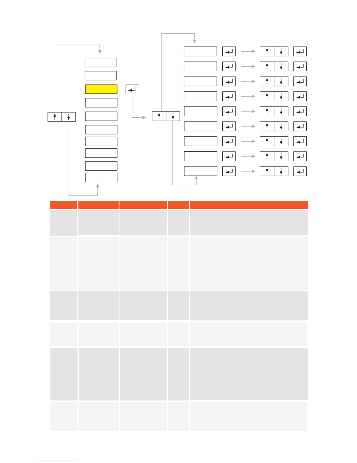
P1 GENERAL
P1.0 PURPOSE OF USE
P1.1 SINGLE INTERVAL /
MULTI RANGE /
MULTI INTERVAL
P1.2 DEFAULT VALUES
P2 PARAMETERS
P2.0 AUTO ZERO TRACKING
P2.1 AUTO ZERO TIME
P2.2 MANUAL ZERO
P2.3 INITIAL ZERO
P2.4 LOAD CELL GAIN RATE
P2.5 ADC INTERVAL FILTER
P2.6 DIGITAL FILTER
P2.7 STANDSTILL DETECT INT.
P2.8 STANDSTILL TIME
P2.9 TARE ENABLE
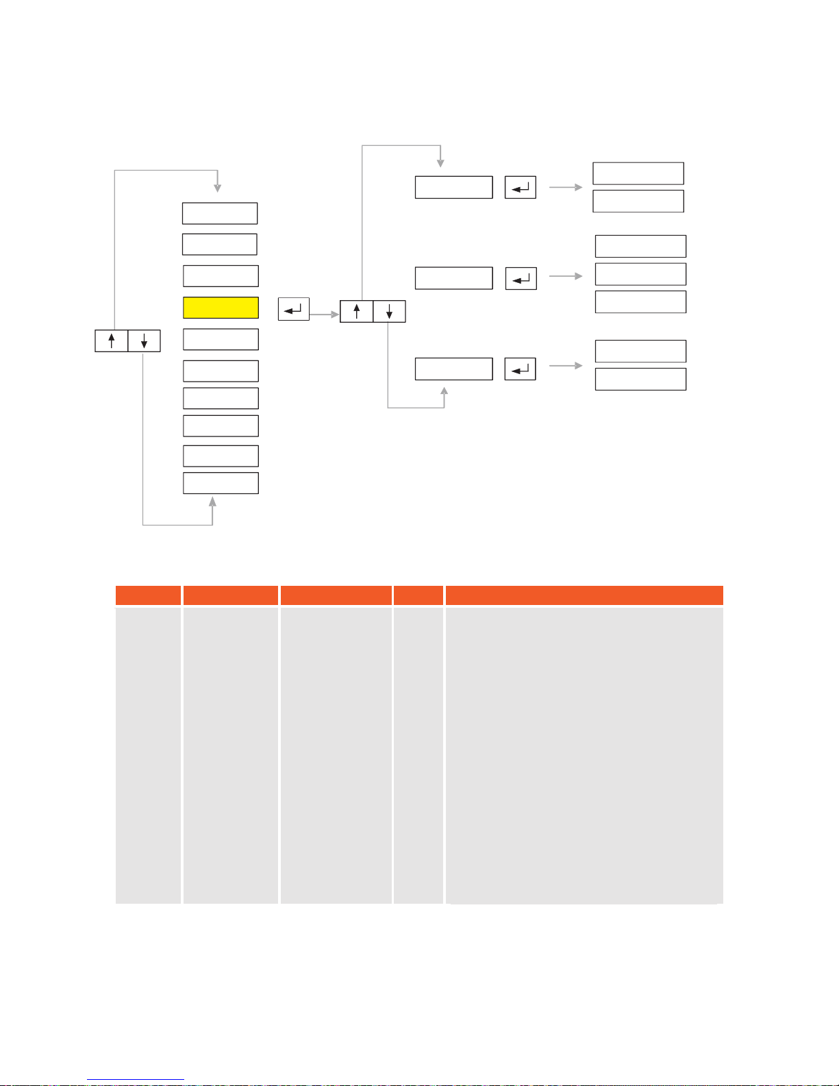
P4 CALIBRATION
P4.0 WEIGHT CALIBRATION
P4.1 SELF CALIBRATION
P4.2 GRAVITY PARAMETERS
P5 PORTS
P5.0 ALIBI MEMORY
P5.1 BAUD RATE FOR COM 1-2
P5.2 BAUD RATE FOR COM 3
P5.3
P5.4
P5.5
P5.6
P5.7
CONTINOUS PORTS
MANUAL PORTS
SLAVE PORTS
ADDRESS
RS 422/485 PORTS
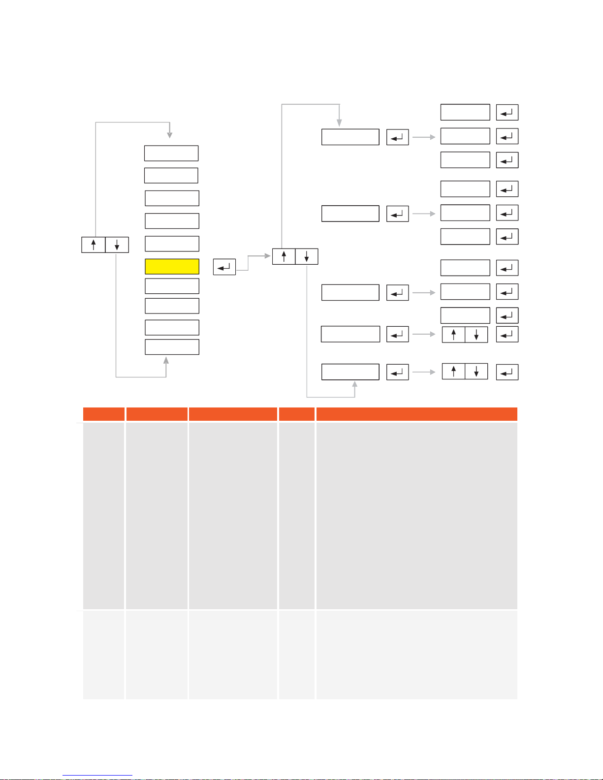
P6 INPUT / OUTPUT
P6.0 OUTPUT OPERATING TYPE
P6.1 OUTPUT ASSIGNING
P6.2 OUTPUT SET WEIGHTS
P6.3 INPUT OPERATING TYPE
P7 PERIPHERALS
P7.0 MIN. LOAD FOR PRINTER
P7.1 TICKET FORMAT
P7.2 TICKET FIELDS
P7.3 TICKET LANGUAGE
P7.4 PAPER TYPE
P9 DISPLAY
P9.0 INTERNAL COUNT
DISPLAY
P9.1 CALIBRATION VALUE
DISPLAY
P8 ANALOG OUT
P8.0 ENABLE / DISABLE
P8.1
P8.2
P8.3
P8.4
RANGE
TYPE
MODE
CALIBRATION
P3 CONFIGURATION
P3.0 CAPACITY 1
P3.1 DIVISION 1
P3.2 DECIMAL POINT PLACE 1
P3.3 CAPACITY 2
P3.4 DIVISION 2
P3.5 DECIMAL POINT PLACE 2
P3.7
P3.6
DECIMAL POINT TYPE
WEIGHING UNIT
P3.8
OVERLOAD
- END -
15
KM.LL2E.002
Page 17
16
SYMBOL NAME ALTERNATIVES DEF. EXPLANATION
P1.0 Purpose of
Use
1
1
0
Non Approved
2
2
Approved
2
P1.1
Default
Values *
-------
P1.2
P1.0
P1.1
P1.2
P1-GEN
P2-PAR
P3-CON
P4-CAL
P5-POR
P6-INO
P7-PRP
P8P9-
-DIS
ANA
-END-
------
5.1. P1-General:
If non approved mode
is selected, indicator
adjustments can be changed without any
restrictions. In approved mode, the data input
will only be accepted if they are convenient to
EN45501 standard.
This option is used to return all of indicators
parameters back to their factory default
values.
KM.LL2E.002
Single Interval
Multi Range
Multi Interval
0
You can select the operation type of the
indicator from this menu. Select 0 for single
Interval, 1 for Multi Range and 2 for Multi
Interval.
Single Interval
Multi Range
Multi Interval
Page 18

P2.1
P2.0
P1.0
P1.1
P1.2
–
–
–
–
–
4
0
2
0
-
P2.2 – 1
P2.3 – 0
P2.4 – 64
P2.5 – 0
P2.6 – 5
P2.7 – 1
P2.8 – 2
P2.9 – 0
P3
P2
P1
–
–
–
CONFIGURATION
PARAMETERS
GENERAL
P3.1
P3.0 –– 1 -
P3.2 – 0
P3.3 – -
P3.4 – 1
P3.5 –
0
P3.6 – 1
P3.7
P3.8 –– 1 2
P5
P4 ––
PORTS
CALIBRATION
P5.0
P5.0 ––
1
-
P5.1
P5.1 ––
9600 -
P5.
P5.22 ––
9600 -
P5.
P5.
P5.
P5.
P5.
3
4
5
6
7
–
–
–
–
–
0
2
1
001
0
P6 – INPUTS / OUTPUTS
P6.0
P6.1
P6.2
–
–
–
0
-
P6.3 – 0
P6.4 – -
P7
P8
P9
P10
–
–
–
–
PERIPHERAL EQUIPMENTS
ANALOG OUT
DISPLAY
END
P7.0
P7.1
P7.2
P8.0
P9.0
P9.1
P8.1
P8.2
–
–
–
–
–
–
–
–
0
-
-
0
-
-
-
0
P7.3
P8.3 –– 0 0
P7.4
P8.4 –– 0 -
17
KM.LL2E.002
* Factory default values are as follows:
Page 19
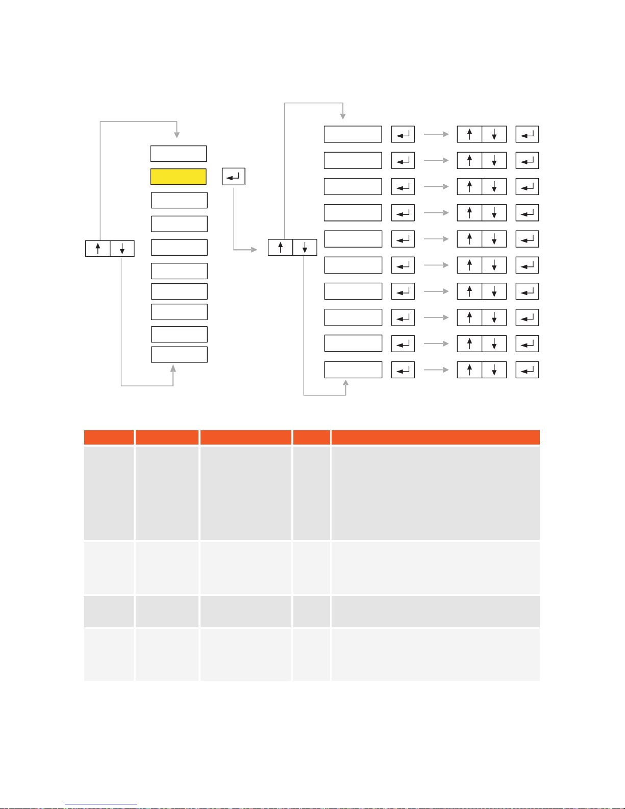
5.2. P2-Parameters:
SYMBOL NAME
ALTERNATIVES DEF. EXPLANATION
P2.0
Auto Zero
Tracking
8 2e
0
Weight vaules smaller than the selected value
will be set automatically to zero.
P2.1
Auto Zero
Waiting
Time
0 0 sec.
1 0,5 sec.
2 1 sec.
3 1,5 sec.
4 2 sec.
4
Time which will be elapsed before auto zero
is activated.
P2.2
Manual Zero 1 %2
2 %20
3 full capacity
1
Select max imum load range that can be
manually zeroed by pushing zero button.
P2.3
Initial Zero
0
Select range which will be zeroed during
start-up.
P2.4
P2.3
P2.6
P2.7
P2.9
P2.8
P2.5
P2.2
P2.1
P2.0
18
0 Disable
1
0.25e
2 0.5e
3 0.75e
4 1e
5 1.25e
6 1.5e
7 1.75e
0 Disable
1 - %1
2 - %5
3 - %10
4 - %20
P2-PAR
P1-GEN
P3-CON
P4-CAL
P5-POR
P6-INO
P7-PRP
P8P9-
-
DIS
ANA
-END-
KM.LL2E.002
Page 20
19
P2.4
P2.5
0 Select filter level against sudden impacts.
P2.6
ADC Internal
Filter
0 100 sps.
1 50 sps.
2 25 sps.
3 12.5 sps.
4 6.25 sps.
P2.7 Standstill
Detection
Interval
1 1e
2 2e
3 3e
4 4e
5 5e
1 If the difference between consecutive weight
values is smaller than this value, standstill
signal will light after the time period selected
at P2.7 is elapsed.
P2.8
Standstill
Waiting
Time
0 0 sec.
1 0,5 sec.
2 1 sec.
3 1,5 sec.
4 2 sec.
2 Select time period
will be elapsed
before
standstill signal lights
(
if the consecutive
weight values are smaller than P2.6).
P2.9 Tar e
Request
0 Tare Enable
1 Tare Disable
0 Tare button can be enabled o r disabled.
KM.LL2E.002
Load Cell
Gain Rate
1 x1
2 x2
4 x4
8 x8
16 x16
32 x32
64 x64
64
Select gain rate of mV sig nal coming from
load cells.
Select 64 for 1 mV/V load cells,
Select 64 or 32 for 2mV/V load cells,
Select 64, 32 or 16 for others.
1, 2, 4 and 8 are dedicated for special
applications.
Digital Filter 0 Disable
1 Last 2
2 Last 4
3 Last 8
4 Last 16
5 Last 32
5 Select filter level. Moving average of last 2
32 weight vaules will be calculated.
Page 21
20
SYMBOL NAME ALTERNATIVES DEF. EXPLANATION
P3.0
P3.3
Capacity 1
Capacity 2
0000000
0000000
.
P3.1
P3.4
Division
Division
Interval 1
Interval 2
(Verification
(Verification
Scale
Scale
Interval)
Interval)
1 1 1
1
2 2 2
2
3 3 5
5
4 4 10
10
5 5 20
20
6 6 50
50
7 7 100
100
8 8 200
200
9 9 500
500
1
1
Scale's division interval ( verification scale
interval.) for weighing range 1. If P1.0
(purpose of use) is selected as approved,
number of divisions can not exceed 3000.
For non-approved applications you can
select up to 50,000 divisions.
Scales division interval ( verification scale
interval.) For weighing range 2. If P1.0
(purpose of use) is selected as approved,
number of divisions can not exceed 3000.
For non-approved applications you can
select up to 50,000 divisions.
P3.2
P3.5
Decimal
Decimal
Point
Point
Place 1
Place 2
0
0
No point
No point
1 1 xxxxx.x
xxxxx.x
2 2 xxxx.xx
xxxx.xx
3 3 xxx.xxx xxx.xxx
xxx.xxx
4
4
0
0
This option is to select place of decimal point
for weighing range 1.
This option is to select place of decimal point
for weighing range 2.
5.3. P3-Configuration:
P3.4
P3.3
P3.6
P3.7
P3.8
P3.5
P3.2
P3.1
P3.0
P2 -PAR
P1-GEN
P3-CON
P4-CAL
P5-POR
P6-INO
P7-PRP
P8P9-
-
DIS
ANA
-END-
Enter maximum capacity of the second
weighing range
Enter maximum capacity of the first weighing
range (If single interval is selected at menu
P4.1,this will be the Maximum Capacity of the
scale)
KM.LL2E.002
xx.xxxx
xx.xxxx
Page 22

21
P3.6 unit 1 kg
2 lb
1 Select weighing unit which will be displayed
and printed on the ticket.
P3.7 Decimal Sign
Type
1 point
2 comma
1
Select sign type (if decimal vaules are used).
P3.8 Overload
0 0 e
1 1 e
2 9 e
3 - %2
2
Select overload value which can be displayed
after full scale capacity.
KM.LL2E.002
Page 23
22
5.4. P4-Calibration:
SY
MBOL
NAME
ALTERNATIVES DEF. EXPLANATION
P4.0
Calibration
With Weight
-------
Note: Maximum capacity and and division
interval values must be set before starting
calibration process.
After
No Load
message appears, make sure
that scales platform is empty
and press
Enter button. Device will show “BUSY”
message.
“Add Load”
message will appear.
P ut
calibration weight on scales platform (min
10 % of full scale,
prefer
ably close to
maximum capacity) and press Enter
button.
Then, write this
calibration weight value
via
keypad and press Enter button. D
evice will
display “ BUSY ” message again
.
After
calibration is completed
, main
menu will be
seen on display. After c
with
alibration weight
process
is implemented, gravity acceleration
values will be zeroed.
P4.2
P4.1
P4.0
No Load
Add Load
Lc Cap
Lc Sens
No Load
Gr-Cal
Gr-Use
P2-PAR
P1-GEN
P3-CON
P4-CAL
P5-POR
P6-INO
P7-PRP
P8P9-
-
DIS
ANA
-END-
KM.LL2E.002
Page 24

23
P4.1
Self
Calibration
-------
P4.2
Gravity
Acceleration
------- Gravity acceleration parameters make it
possible to compensate the
weight difference
between the place in which the instrument is
calibrated (GR-CAL) and the p
lace in which
the instrument will be used (GR-USE)
, due to
different gravity acceleration.
Gravity acceleration values must be between
9,77000 and 9,84000 Enter these two
parameters by using keypad (starting from
left) and press enter button. After that
the
,
weight
corrected.
calibration is automatically
Gravity values at some places are as follows:
2
Amsterdam 9.813 m/s
Athens
Auckland NZ
Bangkok
Birmingham
Brussels
Buenos Aires
Calcutta
Chicago
Copenhagen
Djakarta
Frankfurt
Glasgow
Havana
Helsinki
Kuwait
Lisbon
London (Greenwich)
Los Angeles
Madrid
2
9.800 m/s
2
9.799 m/s
2
9.783 m/s
2
9.813 m/s
2
9.811 m/s
2
9.797 m/s
2
9.788 m/s
2
9.803 m/s
2
9.815 m/s
2
9.781 m/s
2
9.810 m/s
2
9.816 m/s
2
9.788 m/s
2
9.819 m/s
2
9.793 m/s
2
9.801 m/s
2
9.812 m/s
2
9.796 m/s
2
9.800 m/s
This method is used to calibrate the device
without calibrated weigh ts. You must enter
number of load cells (Lc No),
capacity of load
cells (Lc Cap), mi llivolt signal (Lc Sens) and
to let the device sense the dead load of the
scale (No Load) . Finally press Enter
button,
device will show “BUSY” message.
Note: self calibration can be used only for not
legal for trade applications
KM.LL2E.002
Page 25
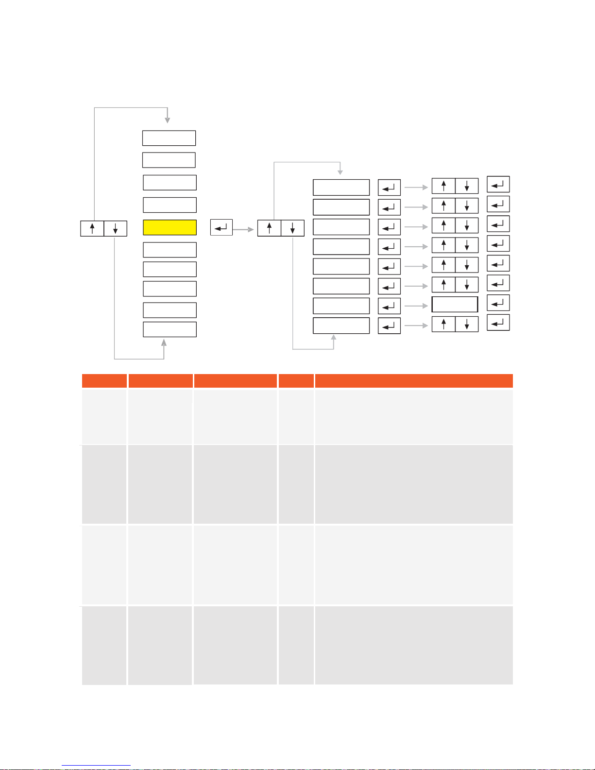
5.5. P5-Ports :
SYMBOL NAME ALTERNATIVES DEF. EXPLANATION
P5.1 Baud Rate for
Ports 1 - 2
300
600
1200
2400
4800
9600
19200
38400
9600
P5.2 Baud Rate for
Port 3
300
600
1200
2400
4800
9600
19200
38400
9600
P5.3 Ports for
Continuous
Data
Transmit
0 Disable
1 Com 1
2 Com 2
3
4
5
6
7
Com 3
Com 1+2
Com 1 + 3
Com 2 + 3
Com 1 + 2 + 3
0
Select port names for continuously transmitting
P5.0
P5.1
P5.2
P5.3
P5.4
P5.5
P5.6
P5.7
24
P2-PAR
P1-GEN
P3-CON
P4-CAL
P5-POR
P6-INO
P7-PRP
P8P9-
-
DIS
ANA
-END-
KM.LL2E.002
P5.0 Alibi Memory 0 Disable
1
1 Enable
Alibi memory can be enabled or disabled.
Capacity of alibi memory is 105.000 records.
When this capacity is exceeded, device will
not send serial data until records in alibi
memory is deleted.
data (data protocol is given in later sectons).
---
Select baud rate of communication Port 3
Select baud rate of communication Ports 1-2
Page 26

P5.4
P5.6
Ports for
Address
Manual Data
Transmit
2
Select port names for manually transmitting
data(data protocol is given in sections).
later
Alibi memory reports can be taken through
this parts.
Slave Ports
RS 422 / 485
0
0
0
Disable
(---)
Disable
Disable
1
1
1
Com 1
Com 1
Com 2
2
2
2
Com 2
Com 2
Com 3
3
3
3
4
4
5
5
6
6
7
7
Com 3
Com 3
Com 2 + Com 3
Com 1+2
Com 1+2
Com 1 + 3
Com 1 + 3
Com 2 + 3
Com 2 + 3
Com 1 + 2 + 3
Com 1 + 2 + 3
Device can be used as slave or master. Select
port names which will be used as slave ports.
Select port names for RS422/485 data
communication. These ports are full duplex.
25 KM.LL2E.002
1
001
0
SYMBOL NAME ALTERNATIVES DEF. EXPLANATION
P5.5
P5.7
Max. of 32. indicators can be connected.
Enter. device's address information here.
If this value is left as zero then the slave
port will not work properly.
Page 27
26
5
.6. P6-Inputs / Outputs:
SYMBOL
NAME
ALTERNATIVES
DEF. EXPLANATION
P6.0
Output
Operating
Type
0 Disable
1 Net Values
2 Brut Values
3 Inputs
0
You can select operating type of each of
outputs.
If 0 (disable) is selected, relevant output will
be disabled.
If 1 (net) is selected, re spective output will
be closed when net weight value is greater
than set point weight (entered at P6.2).
If 2 (brut) is selected, this time brut values
will be compared with set point weights.
If 3 (inputs) is selected, output will work with
respect to inputs, meaning that if one of the
inputs is active, then respective output will be
active (you can assign different inputs to
each of outputs as shown in P6.1).
P6.1
Output
Assign
-------
You can assign different inputs to each of
outputs. First of all s elect output number and
press enter button. Then write respective
in puts you want to assign by using the
following formula:
Input1 x 1 + Input2 x 2 + Input3 x 4 +
Input4 x 8.
P6.1
P6.3
OUT 1
- - - - - -
OUT 4
P6.2
SP 1
- - - - -
SP 4
P6.0
OP 1
- - - - - -
OP 4
P6.4
P2-PAR
P1-GEN
P3-CON
P4-CAL
P5-POR
P6-INO
P7-PRP
P8P9-
-
DIS
ANA
-END-
KM.LL2E.002
Page 28

P6.1 Output
Assign
-------
Press Enter button to go next one. You dont
have to enter all of 4 outputs, you can exit at
any time by using Esc button.
Example: if output 1 is assigned to inputs 1
and 3, select output 1 (Out 1) and press
enter button. Then write
the result of
following formula:
1x1 + 0x2 + 1x4 + 0x8 = 06
P6.2
Output
Set Point
Weights
-------
You can define 4 different set point weights.
Enter set weight value s by using numerical
buttons and then
press Enter button to go
next one. You dont have to enter all of 4 set
values, you can exit at any time by using Esc
button.
Example: if displayed weight value (brut or
net) is smaller than set point 1, output 1 will
be open till it exceeds set point 1. As soon as
weight value is greater than or equal to set
point 1, output 1 is closed.
P6.3
Input
Operating
Type
0 Disable
1 Standard
2 External
Buttons
0
You can select operating type of the set point
inputs.
If 0 (disable) is selected, inputs will be
disabled.
If 1 (standard) is selected, inputs will be
enabled.
If 3 (external buttons) is selected, 1st in put
will be used as tare button, 2nd input will be
used as zero button and 3rd input will be used
as print button.
P6.4
Application
Type
0 Filling
1 Level
Measuring
If 0 is selected , outputs will not be set while
weight is returning back to zero un til zero is
displayed. If 1 is selected , outputs will be set
as soon as weight is smaller than related set
point value.
27
KM.LL2E.002
Page 29
28
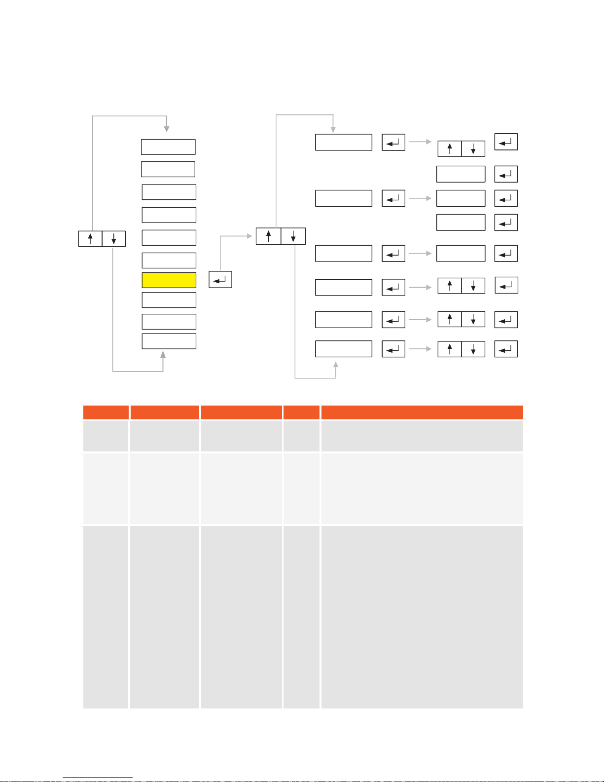
5.7. P7-Peripheral Equipments:
SYMBOL NAME
ALTERNATIVES DEF. EXPLANATION
P7.0
Minimum Load
for Printer
0 0
1 20 e
2 50 e
0
This value shows minimum weight value at
which pinter outputs can be taken.
P7.1
Ticket
Format
-----
Enter number of blank rows from top (Top),
number of blank characters from left (left)
and blank rows at the end (Bottom).
Note: Each of above values must be between
1 to 255.
P7.2
Ticket
Fields
-----
Fields on the ticket can be defined by using
the following formula:
Ticket no x 1 + Firm Name x 2 + Date-Time
x 4 + Code x 8 + Weight x 16 + Barcode x
32.
You must put 1 for the fields you want to
include to the ticket and put 0 for others.
,
Then calculate above formula and enter it to
P7.2
Example: If you want only ticket no and
weight fiel ds on the ticket, then result of the
formula will be equal to:
1x1 + 0x2 + 0x4 + 0x8 + 1x16 + 0x32 = 17.
You must enter 17
P7.1
P7.0
P7.2
TOP- -
LEF - - -
BOT- - -
- - - - - -
P7.3
P7.4
P7.5
P2-PAR
P1-GEN
P3-CON
P4-CAL
P5-POR
P6-INO
P7-PRP
P8P9-
-
DIS
ANA
-END-
KM.LL2E.002
Page 30

29
KM.LL2E.002
SYMBOL NAME
ALTERNATIVES DEF. EXPLANATION
P7.3
Ticket
Language
0 Turkish
1 English
0
Select language which will be used to explain
fields on ticket.
P7.4
Ticket
Paper Type
0 Standard
1 Sticker
0
Select paper type.
Page 31
P8.1
P8.0
P8.2
Brut
0-10V
Net
4-20mA
0-20mA
- - - - - -
- - - - - -
P8.3
P8.4
P2-PAR
P1-GEN
P3-CON
P4-CAL
P5-POR
P6-INO
P7-PRP
P9P8--DIS
ANA
-END-
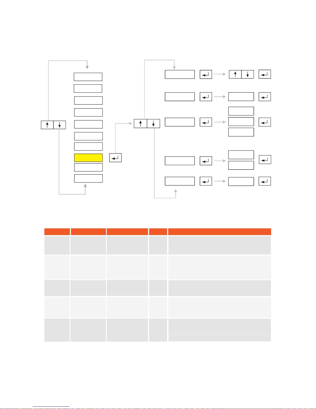
5.8. P8-Analog Out:
SYMBOL NAME
ALTERNATIVES DEF. EXPLANATION
P8.0
P8.2
P8.4
Disable /
Enable
Type
Calibration
P8.1
P8.3
Range
0
1
0
0
Mode
You can enable or disable Analog Out. If
Analog Out is enabled it works continously
within the range given in P8.1
Select one of three analog out operating
types.(0-20mA,4-20mA,0-10V)
This part is used to calibrate Analog Output.
First enter zero value and then maximum
value. Calibration will provide more accurate
analog output value.
Select weight range in which analog out will
work.Analog out will not be active if the
current weight value is not in this range.
(Min. and Max. Weight values)
Select work mode as Brut(0) or Net(1).
KM.LL2E.002
---
--- -
-
0
1
2
0
1
0
30
Page 32
31
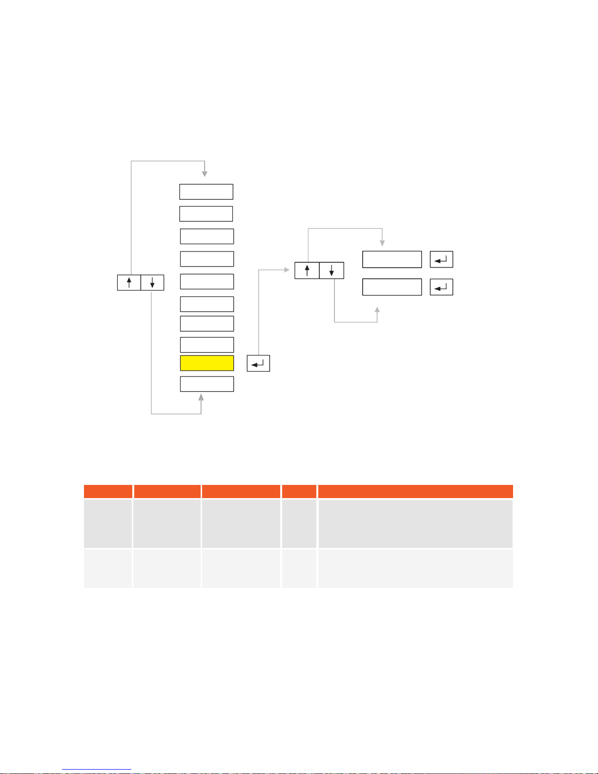
5.9. P9-Display:
SYMBOL NAME
ALTERNATIVES DEF. EXPLANATION
P9.0 Internal Count
Display
-----
P9.1 Calibration
Value Display
-----
Calibration value shows number of internal
counts per one v erification scale interval ( i.e.
slope of calibration line).
P9.0
P9.1
You can change display type from weight
display to in ternal count display by pressing
Enter button at P9.0.
Esc button can be used
to exit.
P2-PAR
P1-GEN
P3-CON
P4-CAL
P5-POR
P6-INO
P7-PRP
P9P8--DISP
ANA
-END-
KM.LL2E.002
Page 33
32
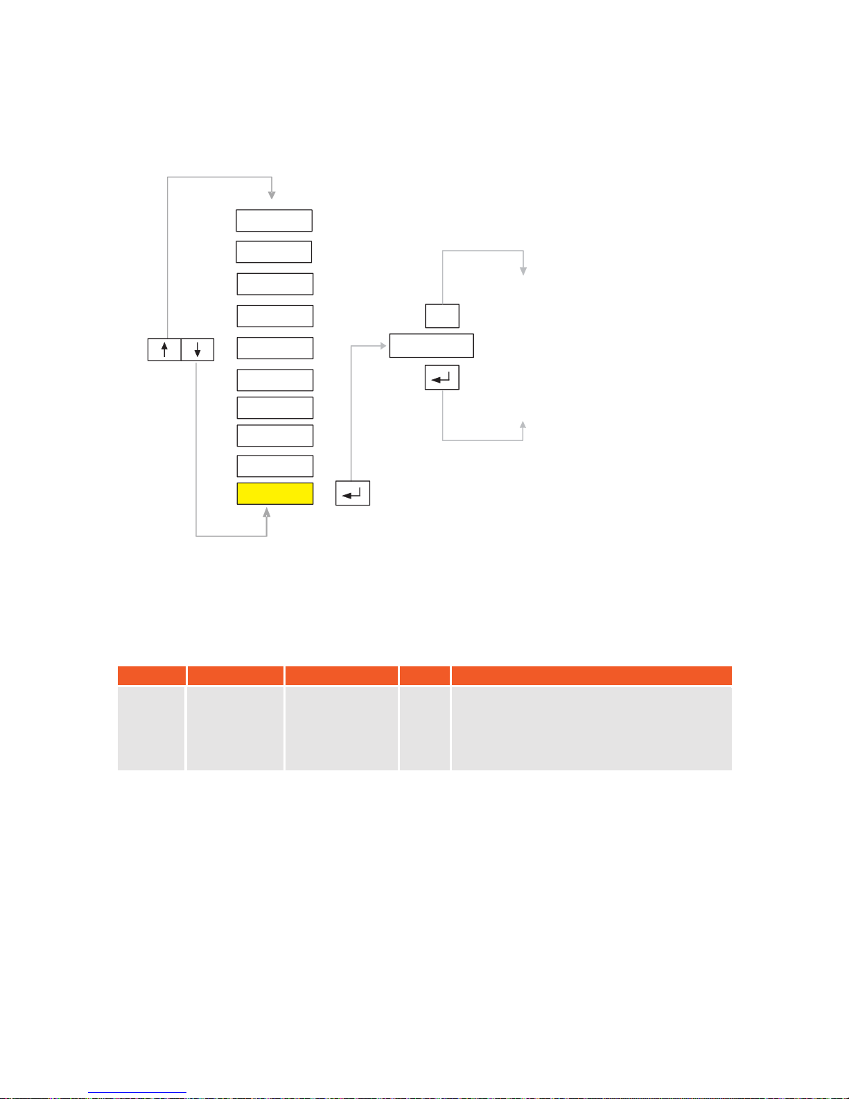
5.10. End :
SYMBOL NAME
ALTERNATIVES DEF. EXPLANATION
In order to exit from programming and
calibration menus, select End ? and press
Enter button. Then Save ?
message will
appear, you can save changes permanently
by pushing Enter button.
SAVE ?
EXIT WITH
SAVE
EXIT WITHOUT
SAVE
ESC
-END-
End (or Exit)
P2-PAR
P1-GEN
P3-CON
P4-CAL
P5-POR
P6-INO
P7-PRP
P8P9-
-
DIS
ANA
-END-
KM.LL2E.002
Page 34
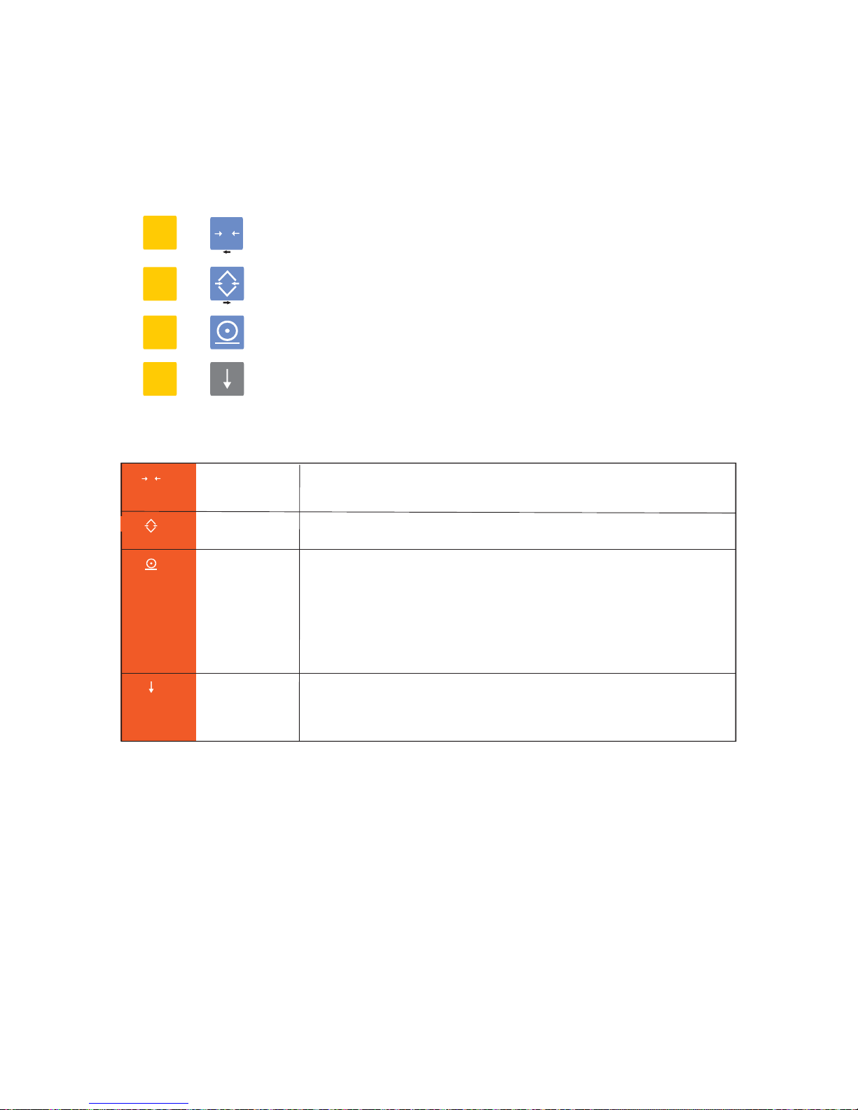
33
6. FUNCTIONS:
F Date
DATE ? message will appear. Press enter button to see and
change date (date format is: ddmmyy)
Time
HOUR ? message will appear. Press enter button to see and
change time (time format is: hh mm)
Hour (Time)
Piece Counting
x10 Viewing
Date
F
F
F
F
T
0
0
F
Piece
Counting
First of all put a few of items you wa nt to count on the scale
and select this function. COUNTIN? message will appear.
Press Enter button and write number of pieces on the scale,
then press enter button again . Number of pieces will be seen
on display and pcs signal will light. Now you can put all of items
you want to count. Use Esc button in order to exit from this
function.
F
x10 Viewing
Ent 10?
message will appear. If you
press
Enter button
verification scale interval will be divided by 10 and device will
be 10 times more sensitive. X10 viewing will last 5 seconds.
F
T
KM.LL2E.002
Page 35
34
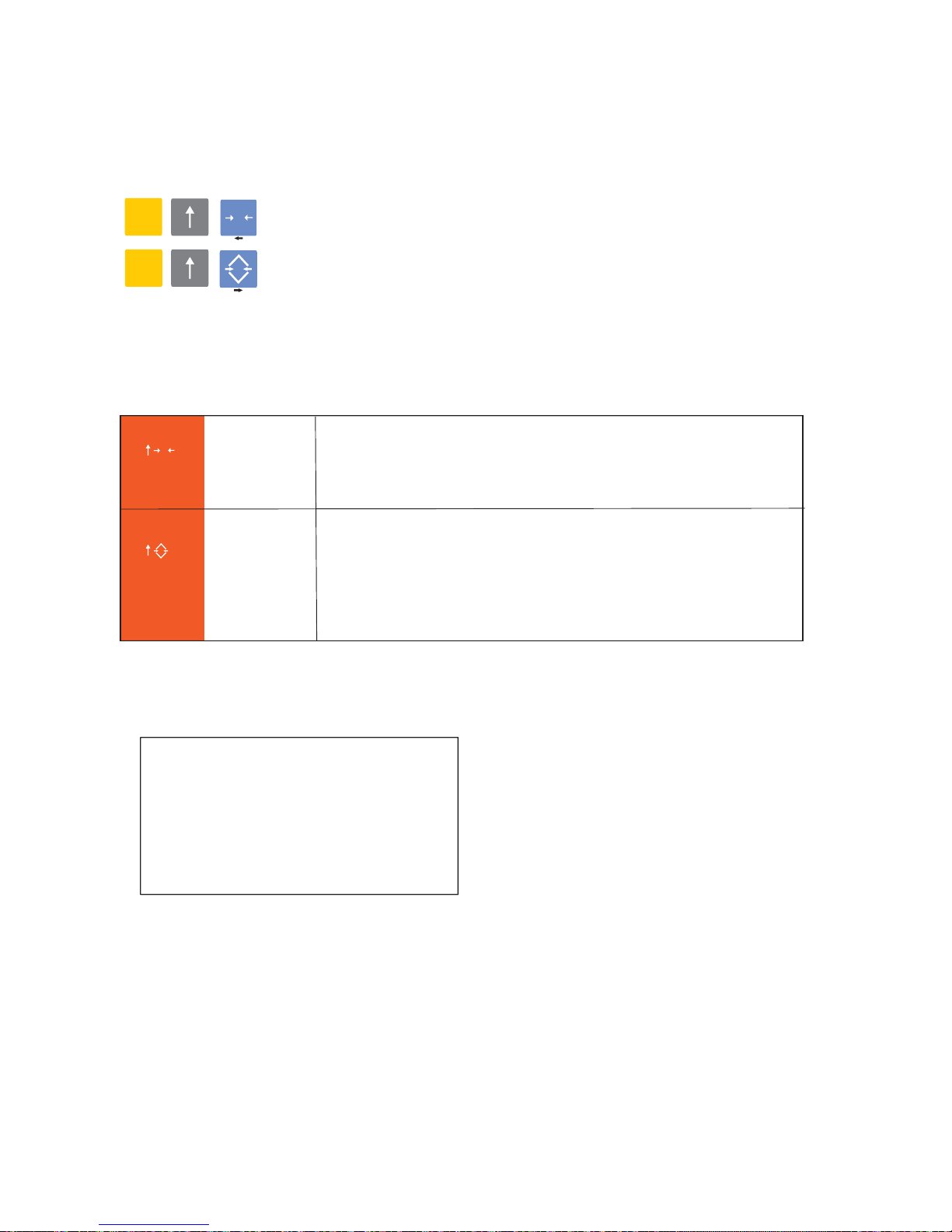
7. ALIBI MEMORY :
010104 10:20
ALL RECORDS
S.NO BRUT TARE NET
000001 13000kg 2000kg 11000kg
000002 15000kg 5000kg 10000kg
000003 17000kg
.....
KM.LL2E.002
printed and
You
You can exit
All Weighing Records
F
0
All Weighing
Records
"ALL" message will be seen, you can print all weighing
records by pushing enter button. You can exit by pushing
Esc button.
Deleting
Weighing
Records
DELETE ? message will appear. If you press Enter button all of
weighing records in the alibi memory will be
deleted. Serial number (ticket number) will also be zeroed.
must clean alibi memory if maximum capacity is reached,
otherwise device will not send data to serial port.
without deleting records by pushing Esc button.
Delete Records in Alibi Memory
F
T
0
F
F
T
Standard Report Example :
Page 36

35
8. SERIAL COMMUNICATION PROTOCOL
8.1. Continuous Data Transmit:
Each package has 21 byte s and starts with Chr(2) and ends up with Chr(13). Serial data
baud rate is adjustable between 300, 600, 1200, 2400, 4800, 9600, 19200, 38400. Data
length is 8 bits and there is no parity . Data will be sent only after standstill condition is
reached. Order of bytes in each package is as follows:
SB: Start Byte (1 Byte)
Chr (2)
A: Status Word (1 Byte)
A.0: Always 1
A.1: 1 for Net
A.2: 1 for Preset Tare
A.3: 1 for Zero
A.4: Not used
A.5: Always 1
A.6: 1 for Negative
A.7: Not Used
B: Status Word 2 (1 Byte)
B.0: Always 1
B.1: 1 for manual print
B.2: Always 0
B.3: Always 0
B.4: Always 1
B.5: Always 1
B.6: Always 0
B.7: Always 0
C: Status Word 3 (1 Byte)
C=0: If there is no decimal point
C=1: If there is 1 character after point
C=2: If there are 2 characters after point
C=3: If there are 3 characters after point
C=4: If there are 4 characters after point
SP: Space (1 Byte)
WEIGHT 1: Displayed Weight Value (6 Byte)
SB CH B C WEIGHT 1
WEIGHT 2
A CK ST SP SP
B6 B5 B4 B2 B1 B0
MSB LSB
KM.LL2E.002
Page 37

B5 B4 B2 B1 B0
MSB LSB
B6
36
WEIGHT 2: Tare Weight (6 Byte)
CH: Character (1 Byte)
Chr (3)
CK: Checksum (1 Byte)
ASCII totals of bytes between SB and CH (with respect to Mod 256)
ST: Stop Byte (1 Byte)
Chr (13)
KM.LL2E.002
Page 38
37
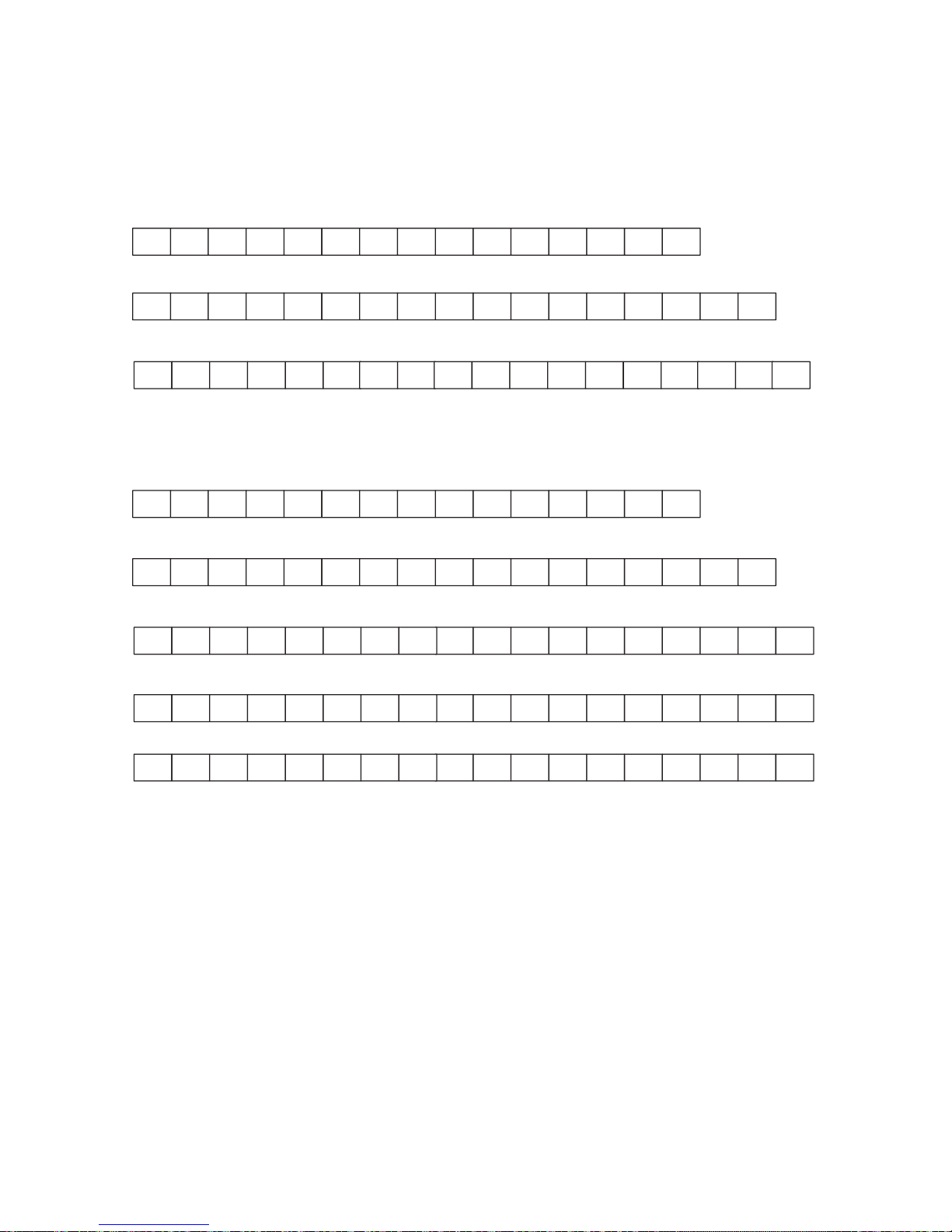
8.2. Manual Data Transmit:
Ticket No:
Date Time:
Weight :
Standard Data Transmit Shape 2 (Net Weight):
Standard Data Transmit Shape 1 (Gross Weight):
Ticket No:
Date Time:
Gross Weight:
Tare Weight:
Net Weight:
D6 D5 / D4 D3
/ D2
SP SP SP D4 D3 :
D1
D2 D1 CH
W E I G H
T
SP D6 D5 D4 D3
:
D2 D1 SP D2 D1 CH
N O : SP
SP SP SP
D6 D5 D4 D3 D2 D1
SP
CH
D6 D5 / D4 D3
/ D2
SP SP SP D4 D3 :
D1
D2 D1 CH
B R U T :
SP SP
D6 D5 D4 D3
SP
D2 D1 SP D2 D1 CH
T A R E :
SP SP
D6 D5 D4 D3
SP
D2 D1 SP D2 D1 CH
N E T : SP
SP SP
D6 D5 D4 D3
SP
D2 D1 SP D2 D1 CH
N O : SP
SP SP SP
D6 D5 D4 D3 D2 D1
SP
CH
KM.LL2E.002
Page 39

38
SP: Space D6, D5, D4, D3, D2, D1: Data
CH: chr (13)
Standard Ticket Examples:
Note: You can modify or change ticket format by using parameters at P7-PRP menu.
NO: 000250
01/01/2004 16:15
BRUT: 00250.5 kg
TARE: 00100.0 kg
NET: 00350.5 kg
Standard Transmit Shape 1
Standard Transmit Shape 2
NO: 000250
01/01/2004 16:15
BRUT: 00250.5 kg
KM.LL2E.002
Page 40

KM.LL3E.001
39
8.3. Master - Slave Communication :
If the ports are configured in slave mode two way and full duplex communication is possible.
To do that, first of all each weight indicator must be addressed. In order to take data from
Slave ports the following characters must be send to the indicator.
As soon as the indicator take these bytes it will send data to master device via the ports which
are dedicated as slave. This communication can be done through RS 232 or RS 422/485. It is
possible to connect up to 32 indicators. Data structure is as follows :
SB
SB
D6
D6
D6
D4
D5
D5
D5
D3
D4
D4
/
:
D3
D3
D4
D2
D1
D2
D2
D3
D1
D2
D1
D1
/
Date Time Weight CK
ST
STRecord No
Address
Address
+
+ +++ ++
+
+
SB : Start Byte
SB
Address : 1 Byte (Address Info)
Address
ST : Stop Byte
Record No :
Weight :
CK : Checksum
ST : Stop Byte
Date :
Time :
: Start Byte
: 1 Byte (Address Info)
Page 41
40
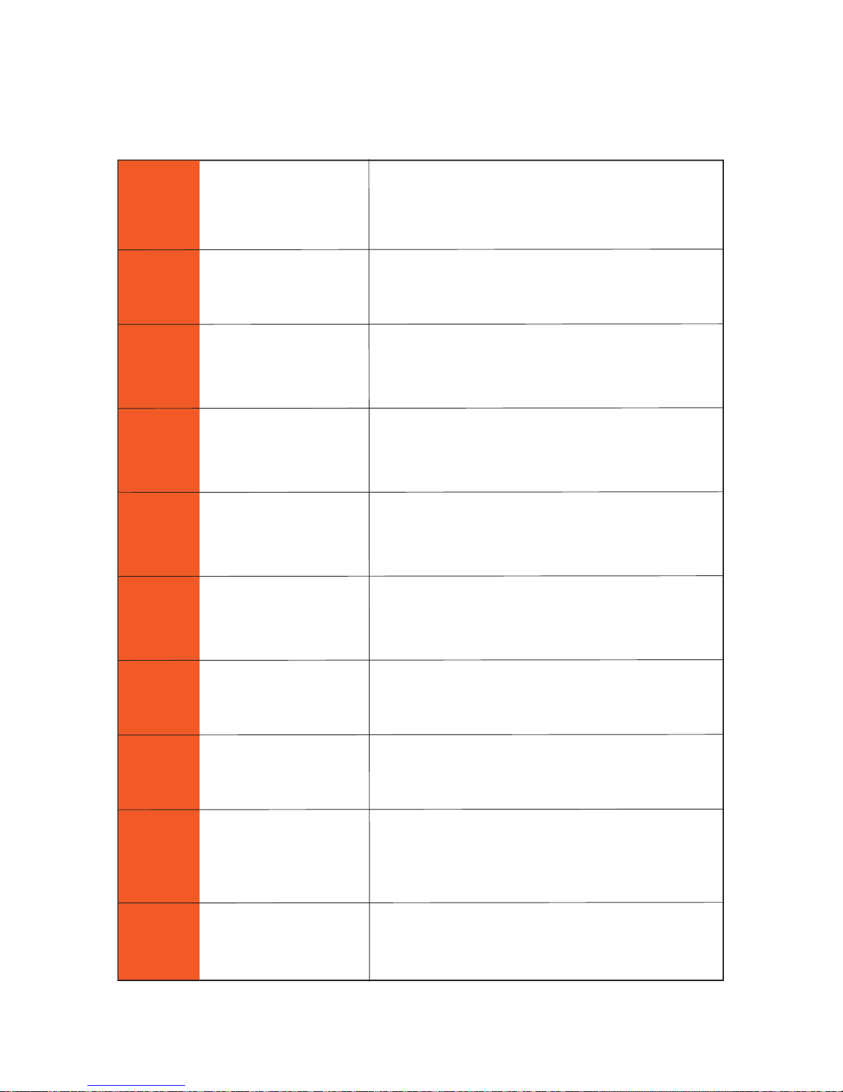
9. ERROR MESSAGES
Error 1 ADC Conversion Error
Restart the device and call our firm if error message
appears again
Error 2 Signal Failure Signals are oppositely connected. Correctit..
Error 3 Weak Signal
Check calibration parameters (especially P3.8) and
steel construction of the scale.
Error 4 Division Number Error
Check maximum capacity and verification scale
intervals.
Error 5 Initialization Error
Restart device. Be sure that load is still while the
device is opening.
Error 6 Calibration Weight Error
Calibration Weight must be greater than or equal to
5% of maximum capacity.
Error 7 Parameter Error Check all parameters.
Error 8
Incorrect Calibration
Password
Check your calibration password and then try again.
Error 10
Calibration jumper does
not exist
Attach calibration jumper. C alibration jumper must
be attached in order to enter some of programming
and calibration parameters.
Error 11 Date Time Error Check date and time parameters.
KM.LL2E.002
Page 42
41
Error 12 Serial Port Selection Error
Ports selected for continuous and manual data
transmit must not be the same.
Error 1
Error 14
3
Lineari
No Load Cell
zation Correction
Error
Difference between manually entered
There is no mV signal coming to the device, check
load cell connection.
value and
displayed weight value must be smaller than +-2%
of displayed value.
Note: If you meet with one of error messages given above, please implement relevant
instructions or call one of our authorized services.
KM.LL2E.002
Page 43
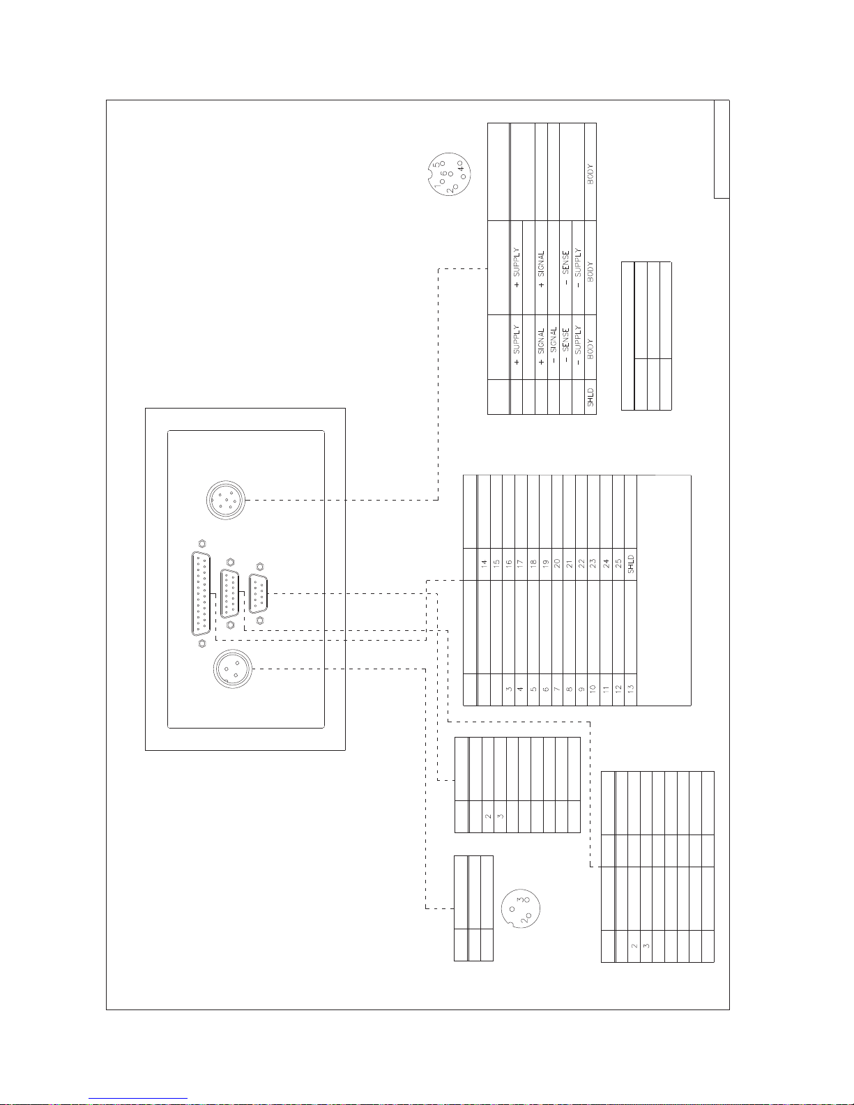
10. CABLE CONNECTIONS (TYPE CTA-CTC-CTB)
42
KM.LL2E.002
TYPE . LL2 CTA-CTB-CTC
547
8
6
1
2
NC
RX2 IN / CTS
TX2 OUT / RTS
RX1 IN
GND
NC
TX1 OUT
0 VDC
+12 VDC
1
LOAD-CELL
( MIC 6 )
1
NC
NC
9
NC
1
TX OUT / RS485 TX+
NC
GND
RX IN/ RS485 TX-
RTS / RS485 RX+
CTS / RS485 RX-
NC
687
4
5
PIN PIN
11
13
12
10
15
14
ANALOG OUT
RS485 RX-
GND
9
A GND OUT
RS485 RX+
RS485 TX-
RS485 TX+
3
SUPPLY
( MIC 3 )
PIN
MEANING MEANING
PIN
- SIGNAL- SIGNAL
+ SENS
LOAD-CELL
MEANING
+ SENS
PIN NO
1
24365
CABLE CONNECTION(6WIRE)
LOAD-CELL
- SUPPLY / - SENSE
+ SIGNAL
CABLE CONNECTOR(4WIRE)
+ SUPPLY / + SENSE
MEANING MEANING
0 VDC
PIN
INPUT 4 C
INPUT 3 D
INPUT 3 C
INPUT 2 D
INPUT 1 D
INPUT 1 C
INPUT 2 C
MEANINGMEANING
COM
COM
COM
PIN
1
2
OUT1 A OPTIC/RELAIS
OUT3 A OPTIC/RELAIS
OUT2 B OPTIC/RELAIS
OUT2 A OPTIC/RELAIS
OUT1 B OPTIC/RELAIS
--BODY
D 0 VDCD 0 VDC
COM
+12 VDC
OUT4 A OPTIC/RELAIS
OUT4 B OPTIC/RELAIS
IPUT VOLTAGE FOR INPUT ............................. C + 5 VDC
MAX CURRENT FOR INPUT ........................... 5 mA
MAX LIMIT FOR RELAIS OUTPUT ..................... 1 A
MAX LIMIT FOR OPTIC OUTPUT ................... 300 mA
OUT3 B OPTIC/RELAIS
INPUT 4 D
I / O
( DB25 MALE )
COM 3
( DB15 MALE )
COM 1/ 2
( DB9 MALE )
COM1/2
SERIAL PORT / RS 232
COM3
SERIAL PORT / RS 422 / 485 - RS 232
ANOLOG OUTPUT
I / O
LOAD-CELL
SUPPLY
J7 and J8
CLOSED - NETWORK
OPEN - FULL DUBLEX
CLOSED - HALF DUBLEX
RS 485 JUMPER SETTING
J7 and J8
J10 and J11
Page 44
KM.LL2E.002
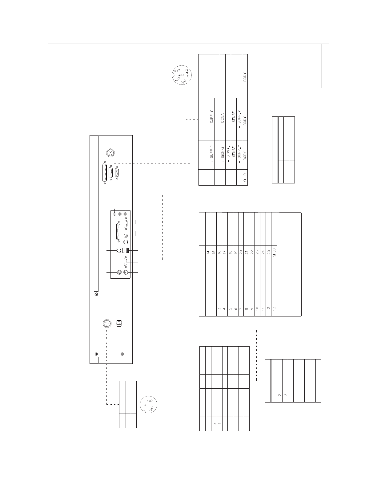
10. CABLE CONNECTIONS (TYPE WT, WT-S)
TYPE . LL2 WT-WTS
INPUT 4 D
OUT3 B OPTIC/RELAIS
MAX LIMIT FOR OPTIC OUTPUT ................... 300 mA
MAX LIMIT FOR RELAIS OUTPUT ..................... 1 A
MAX CURRENT FOR INPUT ........................... 5 mA
IPUT VOLTAGE FOR INPUT ............................. C + 5 VDC
OUT4 B OPTIC/RELAIS
OUT4 A OPTIC/RELAIS
+12 VDC
COM
D 0 VDCD 0 VDC
BODY
---
OUT1 B OPTIC/RELAIS
OUT2 A OPTIC/RELAIS
OUT2 B OPTIC/RELAIS
OUT3 A OPTIC/RELAIS
OUT1 A OPTIC/RELAIS
2
1
PIN
COM
COM
COM
MEANING MEANING
INPUT 2 C
INPUT 1 C
INPUT 1 D
INPUT 2 D
INPUT 3 C
INPUT 3 D
INPUT 4 C
PIN
0 VDC
+ SUPPLY / + SENSE
CABLE CONNECTOR(4WIRE)
+ SIGNAL
- SUPPLY / - SENSE
LOAD-CELL
CABLE CONNECTION(6WIRE)
56342
1
PIN NO
+ SENS
MEANING
LOAD-CELL
+ SENS
- SIGNAL - SIGNAL
PIN
MEANING
3
9
NC
NC
1
TX1 OUT
NC
GND
RX1 IN
TX2 OUT/ RTS
RX2 IN / CTS
NC
687
4
5
COM 1/2
( DB9 MALE )
COM 3
( DB15 MALE )
I / O
( DB25 MALE )
LOAD-CELL
( MIC 6 )
COM3
SERIAL PORT / RS 422 / 485 - RS 232
ANOLOG OUTPUT
COM1/2
SERIAL PORT / RS 232
LOAD-CELL
I / O
J7 and J8
CLOSED - NETWORK
OPEN - FULL DUBLEX
CLOSED - HALF DUBLEX
RS 485 JUMPER SETTING
J7 and J8
J10 and J11
POWER
SWITCH
PS2_KB
PS2_MS
LAN RJ45
Parellel (LPT1)
VGA Out
USB
S-Video
RCA/SPDIF
COM1
Line-In
Line-Out
Microphone
SUPPLY
( MIC 3 )
NC
1
TX OUT / RS485 TX+
NC
GND
RX IN/ RS485 TX-
RTS / RS485 RX+
CTS / RS485 RX-
NC
687
4
5
PIN PIN
11
13
12
10
15
14
ANALOG OUT
RS485 RX-
GND
9
A GND OUT
RS485 RX+
RS485 TX-
RS485 TX+
MEANING MEANING
43
1
2
0 VDC
+12 VDC
1
PIN
MEANING
SUPPLY
Page 45
44
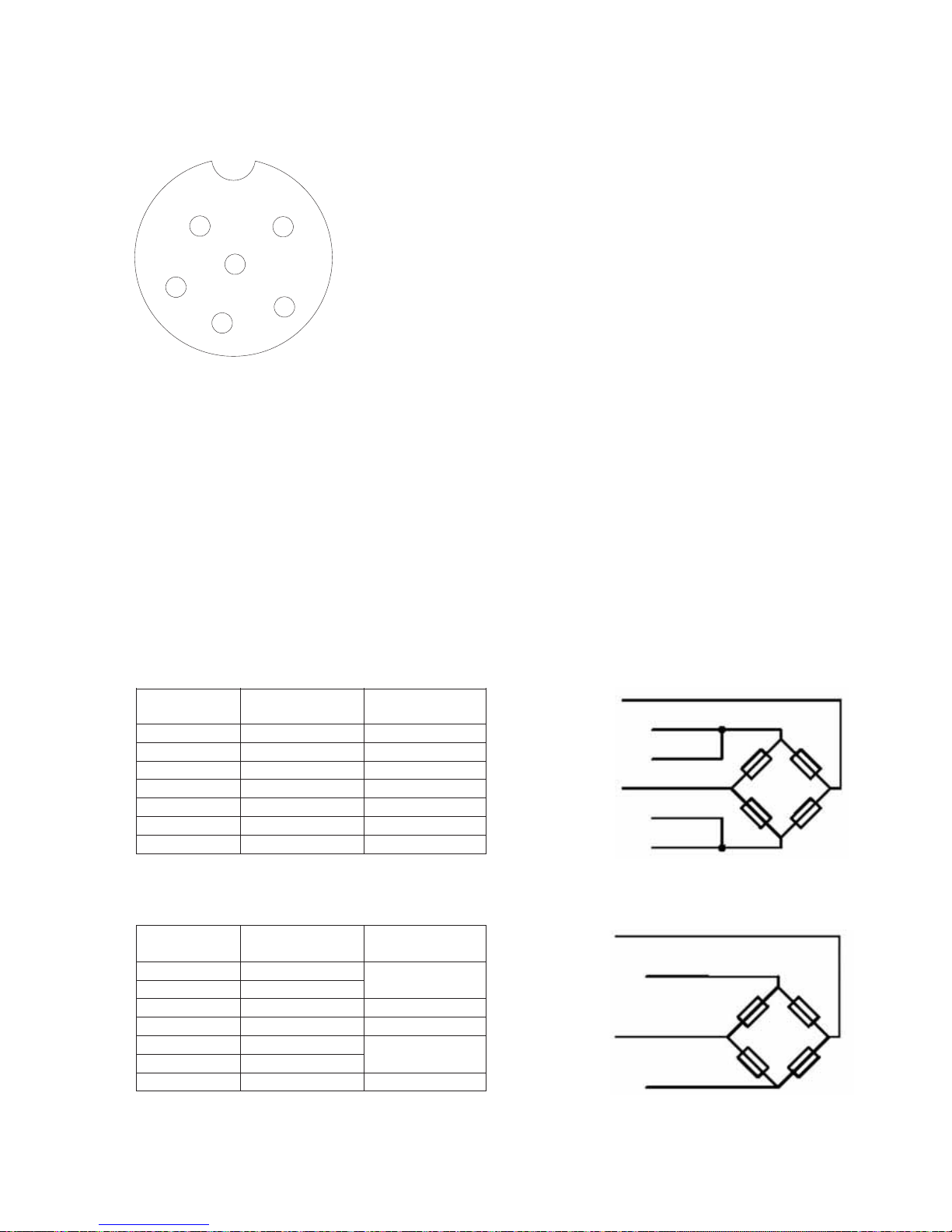
10.1 Load Cell Connection :
The load cell cable must not be channelled with other cables (i.e. outputs connected to
remote switches or power supply wires), but must follow its own route.
Any cable extensions must be carefully shielded, respecting the colour codes and using
the
same type of wire as that supplied by the manufacturer. The extension connections
must be
soldered or connected through support terminal blocks or the joint block
supplied separately.
The load cell wire must not have more conductors than those effectively used (4 or 6). In
the case of a 6-conductor wire, of which only 4 are used ( excitation + and -, signal + and
-), connect the sense + and -wires to the respective polarities of the excitation wires.
A maximum of eight 350-
ohm load cells can be connected to the instrument in parallel.
The load cell
excitation voltage is 5 Vdc and is protected against a temporary short
circuit.
6 Wire:
PIN NO DESCRIPTION SIGNAL -
SIGNAL -
EXCITATION +
EXCITATION +
SENSE +
SIGNAL +
SIGNAL +
SENSE -
EXCITATION -
EXCITATION -
CABLE
CONNECTION
1 + SUPPLY + SUPPLY
2 + SENSE + SENSE
3 + SIGNAL + SIGNAL
4 - SIGNAL - SIGNAL
5 - SENSE - SENSE
6 - SUPPLY - SUPPLY
SHLD BODY BODY
4 Wire:
PIN NO DESCRIPTION CABLE
CONNECTION
1 + SUPPLY
2 + SENSE
+ SUPPLY /
+ SENSE
3 + SIGNAL + SIGNAL
4 - SIGNAL - SIGNAL
5 - SENSE
6 - SUPPLY
- SENSE /
- SUPPLY
SHLD BODY BODY
5
1
6
3
4
2
KM.LL2E.002
Page 46
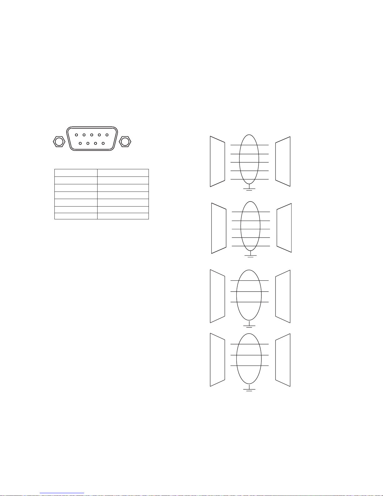
45
10.2 Serial Connections :
In order to create the serial connection use a shielded cable, making sure that only one
of the two shield ends is groun
ded. If the cable has more conductors than those used,
connect the free conductors to the shield.
The serial connection wire must be a maximum of 15 metres long ( EIA RS-232-C
standards), in addition to which it is necessary to adopt the Rs422 interface th at the
instrument can be equipped with.
The cable must not be channelled with other cables (i.e. outputs connected to remote
switches or power supply wires), but must follow its own route. The PC used for the
connection must conform to the EN 60950 standard.
Com 1/2: (RS 232)
PIN NO DESCRIPTION
2 RXD
3 TXD
5
GND
SHLD
7 8 7
BODY
RTSRTS / TX 2
CTS / RX 2
COM2:
COM1:
2
2
3
3
5
5
7
7
7
4
8
8
8
5
3
2
2
3
5
7
PC,
PC,
PRINTER,
PRINTER,
ETC.
ETC.
LOAD
LOAD
LINE
LINE--22
9 Pin
25 Pin
9 Pin
9 Pin
1 5
9 6
8
8
7
7
5
5
3
3
2
2
5
7
PC,
PC,
PRINTER,
PRINTER,
ETETC.
C.
LOAD
LOAD
LINE
LINE--
2
2
9
25 Pin
Pin
9 Pin
9 Pin
KM.LL2E.002
Page 47
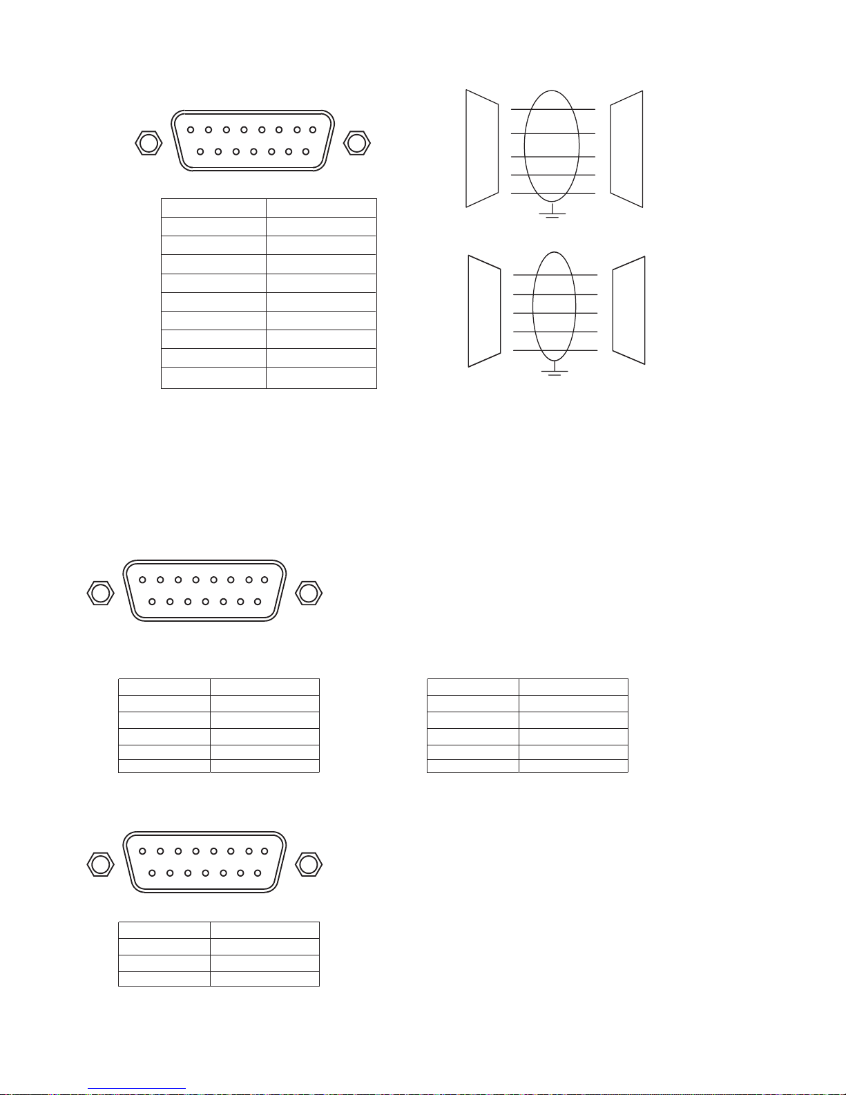
46
10.3 COM3 (RS422/485) Serial Connection :
10.4 Analog Ouput (Optional) :
- The serial connection cable must be suitable for Rs485 serial communications, with two
twisted pairs and relative protective shielding.
- The cable must not be channelled with other cables (i.e. outputs connected to remote
switches or power supply wires), but must follow its own route.
- The PC used for the connection must conform to the EN 60950 standard.
Com Com 3: (RS 422/485 Optional) 2
(DB 15 MALE)
3 (RS 422/485) 1:
PIN NO PIN NO
PIN NO
DESCRIPTION DESCRIPTION
DESCRIPTION
12 2
9
RS485 RX- RS485 TX-
A GND OUT
13 3
10
RS485 RX+ RS485 TX+
ANALOG OUT
RS485 TX- RS485 RX+
BODY
RS485 TX+ RS485 RX-
14 7
SHLD
15 8
SHLD SHLD
BODY BODY
KM.LL2E.002
Com 3: (RS 422/485 - RS 232)
2
3
5
74
85
2
3
7
PC,
PRINTER,
ETC.
LOAD
LINE-2
25 Pin
15 Pin
2
3
5
3
2
5
PC,
PRINTER,
ETC.
9 Pin
15 Pin
7
7
8
8
LOAD
LINE-2
18
915
PIN NO DESCRIPTION
1
2
3
4
5
6
7
8
SHLD
NC
RX IN
TX OUT
NC
GND
NC
RTS
CTS
BODY
COM3:
Page 48
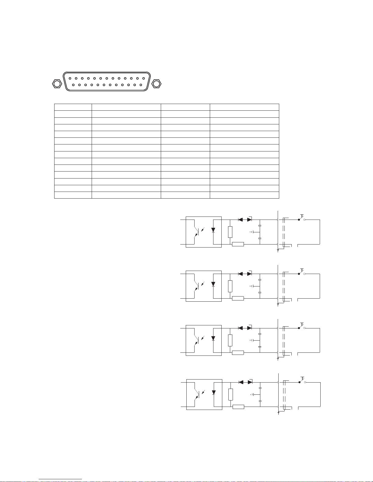
47
10.5 Inputs / Outputs
PIN NO DESCRIPTION PIN NO DESCRIPTION
1 OUT 1A 14 0VDC
2 COM 15 INPUT 1C
3 OUT 1B 16 INPUT 1D
4 OUT 2A 17 INPUT 2C
5 COM 18 INPUT 2D
6 OUT 2B 19 INPUT 3C
7 OUT 3A 20 INPUT 3D
8 COM 21 INPUT 4C
9 OUT 3B 22 INPUT 4D
10 OUT 4A 23 11 COM 24 12 OUT 4B 25 13 +12VDC SHLD BODY
Inputs:
The logic inputs are electrically isolated
from the instrument through opto-isolators.
- Use the shortest possible connection
wire.
The inputs are active when a voltage of 5
Vdc is applied (PNP logic).
In order to activate a logic input, it is
necessary to close the relative terminal
supplied by external power.
113
14
25
+5 V
22
-
+5 V
20
21
-
19
+5 V
+5 V
18
-
17
16
-
15
KM.LL2E.002
Page 49
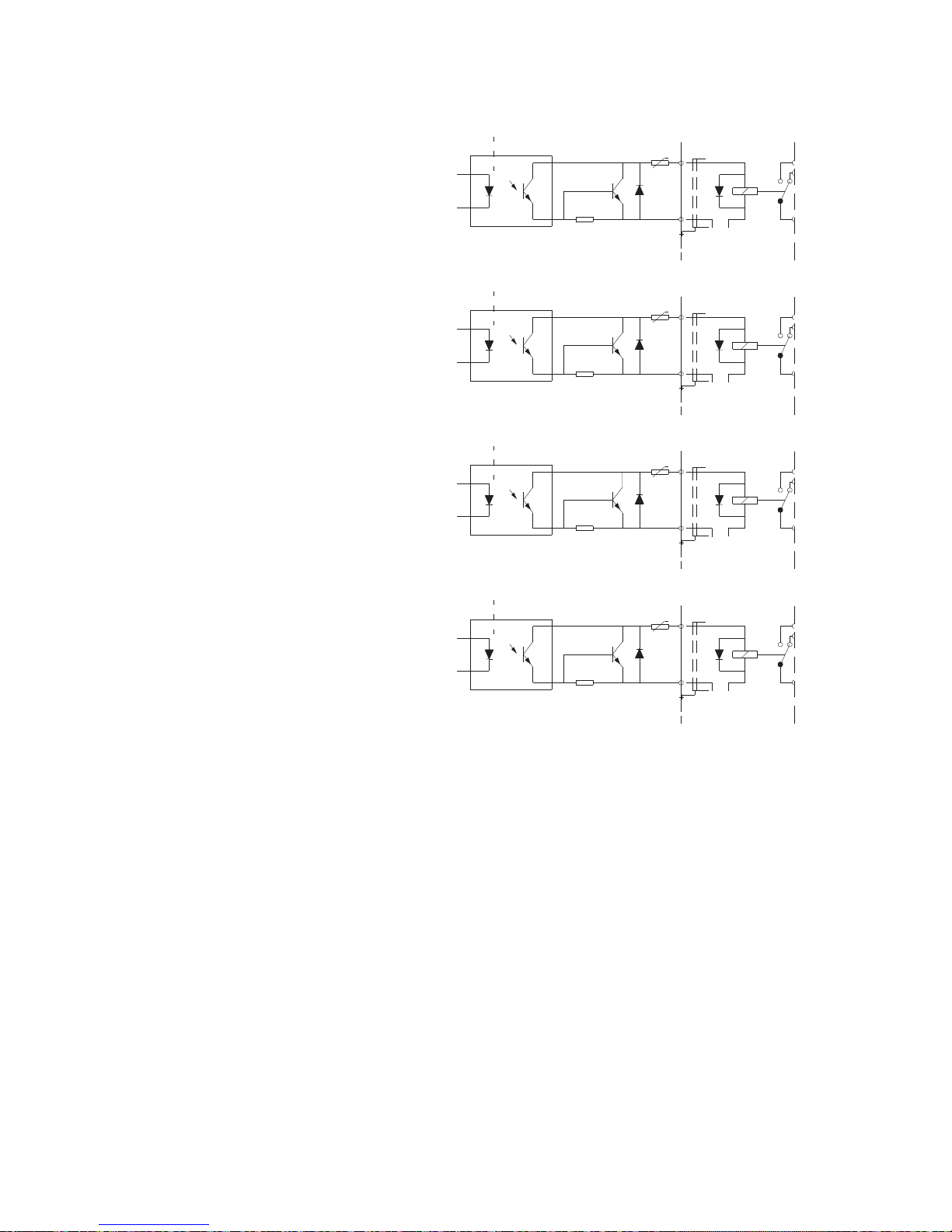
Outputs:
The logic outputs are electrically isolated
from the instrument through opto - isolators.
The l
ogic outputs are provided on a 4
relays, the rate of each contact is 1A/24Vdc
or 0.5A / 12
5 Vac. Each output is
free
programmable.
48
TRANSISTOR
OUTPUT
TRANSISTOR
OUTPUT
TRANSISTOR
OUTPUT
TRANSISTOR
OUTPUT
RELAIS
OUTPUT
12
- +
RELAIS
OUTPUT
11
- +
- +
10
RELAIS
OUTPUT
9
7
8
RELAIS
OUTPUT
5
6
4
- +
3
2
1
KM.LL2E.002
Page 50

49
10.6 Power Supply
PIN NO DESCRIPTION
1 +12VDC
2 0 VDC
The power supply wire must be grounded and must be channelled separately from other
supply wires with different voltages, from the load cell wires and the logic input/output
wires.
Supply voltage: 12VDC ~ 50/60 Hz
The instrume nt is grounded for practical reasons, therefore check the presence of valid
ground protection.
1
2
3
KM.LL2E.002
Page 51
KM.LL2E.002
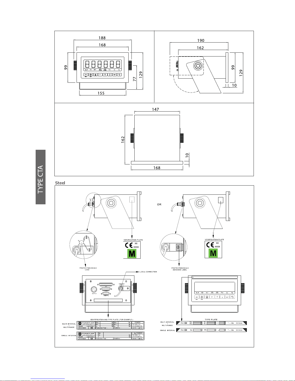
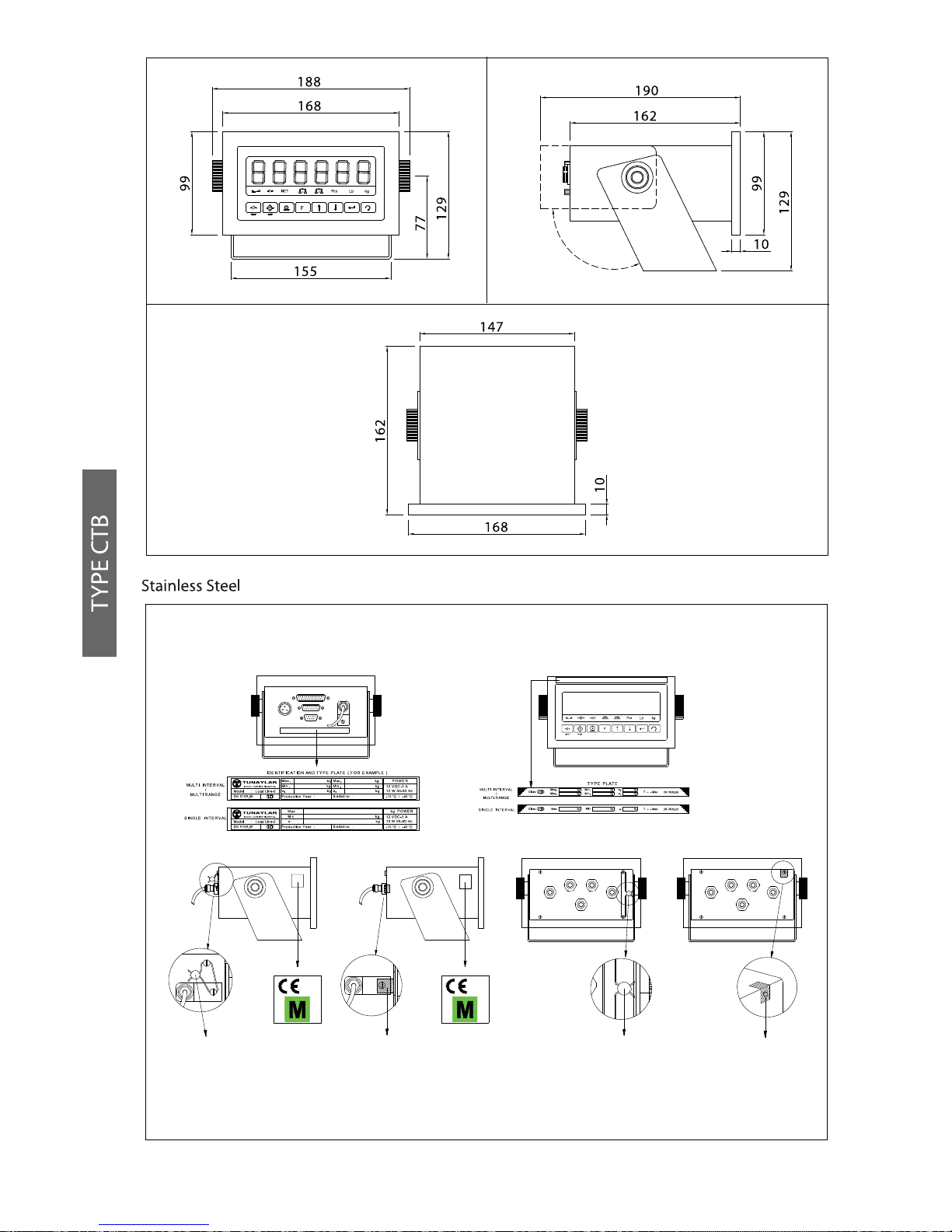
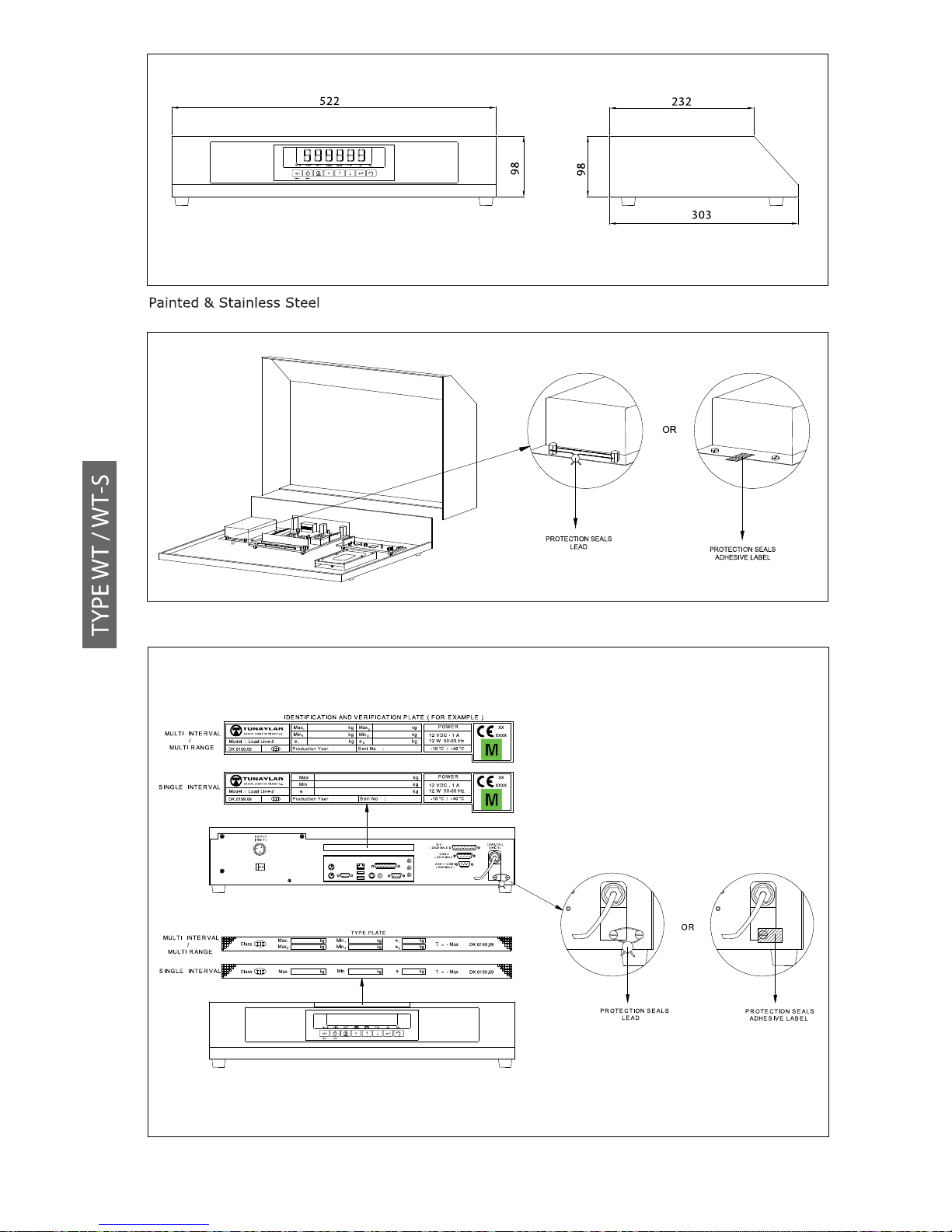
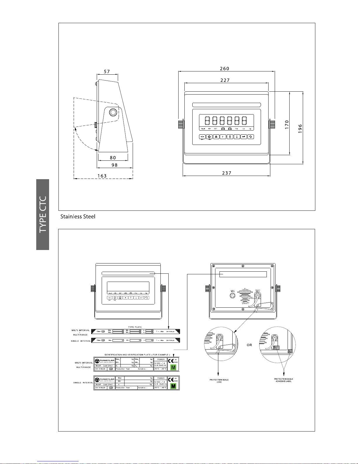
11 . DRAWINGS & SEALING PLANS
50
Page 52
51
KM.LL2E.002
VERIFICATION PLATE
XX
COM 1 / COM 2
( DB9 MALE )
COM 3
( DB15 MALE )
LOAD-CELL
( MIC 6 )
I / O
( DB25 MALE )
SUPPLY
( MIC 3 )
PROTECTION SEALS
LEAD
PROTECTION SEALS
ADHES IVE LABE L
OR
XX
VERIFICATION PLATE
XXXX XXXX
PROTECTION SEALS
ADHES IVE LABE L
OR
PROTECTION SEALS
LEAD
TYP E IP 65
SUPPLY
( MIC 3 )
I / O
( DB25 MALE )
COM 3
( DB15 MALE )
COM 1 / COM 2
( DB9 MALE )
LOAD-CELL
( MIC 6 )
LOAD-CELL
( MIC 6 )
COM 1 / C OM 2
( DB9 MALE )
COM 3
( DB15 MALE )
I / O
( DB25 MALE )
SUPPLY
( MIC 3 )
TYP E IP 65
Page 53
KM.LL2E.002
52
Page 54
KM.LL2E.002
53
Page 55

KM.LL2E.003
 Loading...