

Page 1
NO: 98856604 F 1/2019
TUME-AGRI OY
User manual
JC 3000 Star XL
JC 4000 Star
Seed Drill
Valid for serial numbers AH 53053 – onward
Read this manual before commissioni ng!
Translation
Page 2

2
EC Declar ation of Con form ity for the M ach ine
(Machine Directive 2006/42/EC, Annex II A)
Manufacturer: Tume-Agri Oy
Add.: Sudenkorventie 1
FI - 14200 TURENKI
Name and address of person authorized to compile a technical file:
Name: Heimo Valli Address: Sudenkorventie 1, FI-14200 Turenki
Hereby declares that
Seed drills JC 3000 Star XL ja JC 4000 Star Serial number ___________________
• are in compliance with the applicable decrees of the Machine Directive
(2006/42/EC)
and in addition declares, that
• the following standardized European directives and standards have been applied:
SFS-EN ISO 12100-1:2003
Place and date: Turenki 3.2.2017
Signature:
Patrik Jungarå
Managing Director
Page 3

3
Table of Contents
1. For the machine user and others responsible for the machine ............. 4
2. General safety regulations ................................................................... 4
3. Intended use of the m achine ................................................................ 6
4. Machine commissioning ...................................................................... 7
5. Drawbar installation ........................................................................... 10
6. Feeding equipment ground wheel ...................................................... 16
7. Filling the container ........................................................................... 17
8. Emptying containers .......................................................................... 19
9. Seed feeding equipment and adjustments ......................................... 20
10. Fertilizer feeding equipment and adjustments ................................. 22
11. Sowing table examples ................................................................... 25
12. Calibration test ................................................................................ 26
13. Field test ......................................................................................... 30
14. Fertilizer application depth adjustment ............................................ 30
15. Adjusting the sowing depth ............................................................. 31
16. Harrow adjustment ......................................................................... 33
17. Fertilizer coulters ............................................................................ 34
18. Seed coulters.................................................................................. 34
19. Area meter ...................................................................................... 35
20. Drill maintenance ............................................................................ 36
21. Most common repairs ..................................................................... 38
22. Decommissioning the machine ....................................................... 43
23. Technical Information ..................................................................... 43
24. Optional equipment and accessories .............................................. 44
Annex 1: Lubrication points.
Page 4

4
1. For the machine user and others responsible for the
machine
We wish you every success with your TUME seed drill. This instruction manual provides best-practice
instructions for the use, adjustment, maintenance and storage of Tume JC -machinery. Following the
instructions in this book will ensure that your machine will pr o vide you with lon g, trouble-free service.
It is very important that you familiarize yourself with the instructions before making full-time use of the
machine. Please retain this manual and keep it in an easily accessible location. The replacement part number
of the manual is printed on t he cover . Pleas e m ake a rec ord of this num ber , as it will enable you to order a
new copy should the need arise.
Both the manufacturer, Tume-Agri Oy, and authorized resellers will be happy to provide assistance in
questions relating to the use or maintenance of this machine.
About the presentation of this manual
As this publication is distributed across our international sales network, the equipment depicted in illustrations
(both the standard equipment and accessories) may vary based on the country in which you are located. For
certain countries, covers may for lega l and otherwise im portant reasons be opened or removed in cert ain
illustrations in order to provide a clearer view of the object in question. The machine must not be used without
protective covers. In order to guar antee safe us e, you m ust ensure that all covers are intact or instal led in
place before starting work.
When a reference is made in this manua l t o "l ef t" a nd " right " si des , t his is when viewed from the rear of the
machine looking forwards in the direction of travel.
Tume-Agri Oy is c ontinually deve loping its products, and therefore reserves the right to make changes and
improvements without prior notice and with no commitment to m ake retro-active changes to any prod ucts
sold prior to the changes.
2. General safety regulations
All persons handling, maintaining or who have any form of access to a TUME-seed drill must be
thoroughly familiar with this instruction manual before using, or performing maintenance or repairs
on the machine. Be sure to comply with the instructions in this manual!
Entrust the performance of difficult repairs to an authorized brand repair shop.
Use only original Tume parts, and do not make structural modifications to the machine without the
agreement of the manufacturer.
Working or being located under a machine without supported hydraulics is strictly prohibited.
Secure the position of the machine by closing the lift cylinder safety vents, see Figs. 38-39. If you
must leave the machine unattended, lower the machine and lock the markers mechanically.
Staying on the machine or on the step level when the ma chine is in motion is strictly prohibited.
The driver must ensure that no persons are close by when the machine is in motion or when
hydraulic functions such as engine or lowering or raising markers are being used.
Before reversing the machine, make sure that no one, e.g. children, is standing to its rear.
Page 5

5
Work machine lubrication, adjustments and cleaning are prohibited while the machine is in motion.
Turn off the tractor engine and apply the hand brake during all maintenance. Ensure that no
outsider can access the control equipment of th e tractor or machinery when you are maintaining or
repairing the machine!
A
ll covers must be mounted in position when the machine is in operation.
Ensure that the traction device, hydraulic lines and electrical wiring are correctly connected to the
tractor and work machine. Lines and cables must be laid out in such a way that they are not at risk
of damage when the machine is in use.
Damaged hydraulic lines and connectors must be replaced without delay Tractor hydraulic vents
and connections must not leak and must be in good condition. These ensure the correct transport
position of the machine.
Hydraulic markers may raise or lower at high speed, especially if the throttle valve is set too wide
or if the hydraulic flow rate produced by the tractor is high. Be particularly careful when attempting
to raise or lower the markers for the first time. Ensure that nobody is under or in the path of th e
hydraulically-raised markers.
The markers must be mechanically locked into their upper position before transporting the
machine by road, or when the machine is parked and the machine driver is not present.
Ensure that a minimum of 20% weight is placed on the tractor’s front axle under all conditions. Use
additional weights as required. Be particularly careful if connecting suspension arms to the tractor.
The maximum permissible driving speed under good conditions is 30 km/h. On uneven terrain,
special care must be taken, and speed must be reduced. Transfers should preferably be performed
with empty containers. Carrying loads on top of the machine is prohibited. Do not drive over rocks
or other obstacles so as to avoid tire damage.
Use caution when moving on top of the machine to carry out cleaning or maintenance, or when
filling the containers.
Make sure that the machine is carefully parked when disconnecting the machine from the trac to r.
The machine must be mechanically prevented as required from rolling downhill. The machine’s
lifting hydraulics should be locked at the stopcocks (see Figs. 38–39), markers should be
mechanically locked into their transport position and the hydraulic lines to the tractor must be
depressurized. The tow bar must be supported with a machine support stand.
When heated, coated surfaces may emit vapors that are harmful to human health. Ensure that work
premises are properly ventilated, for example during welding. Remove the paint if necessary, e.g.
by abrasion.
Use only manufacturer-approved accessories and equipment. Modifications which do not comply
with the manufacturer’s instructions an d th e consequences thereof are the responsibility of the
party performing such modifications.
We in particular recommend the use of optional eye protection and a respiratory mask, especially
when filling the seed dressing device. The use of protective equipment is particularly important
when cleaning the machine with a high-pressure device.
The seed drill does not significantly increase noise levels inside the working area of the tractor
cabin. Ear protectors may need to be used, dependent on tractor noise levels.
We recommend that safety boots be worn when handling heavy or sharp components (such as
parts of the tow-bar and coulter).
You should also keep your machine up-to-date in terms of the required equipment for road use, in
the event that the machine must be transported on public roads. Road use regulations may often
change
Page 6

6
3. Intended use of the machine
The TUME JC seed dril l can be us ed to p lant m os t comm on grain, oil and herbac eous plant se eds, as we ll
as peas and beans. Gr anular fertilizer c an also be planted usin g a fertilizer dr ill. Seed dressing a nd grass
seed drills ma y be acquired as optional equipm ent. Such equipment enables dressing during dr illing and
grass seed planting to protect the seeds. In addition, the mac hine can be used separ ately for fer tilizing or
drilling only.
Seeds and fertilizers needed for work can be transported to nearby fields in machine containers if the roads
used for transport are in g ood condition. T he maximum permissible driving speed in this c ase is 15 km/h.
On uneven roads a nd long dri ves, transport must be car ried out with the machine in em pty condition. The
machine may not be used to transport anything els e but seeds and ferti lizers required for immediate use,
and no additional load, objects, animals or passengers are allowed in the containers or on top of the machine.
General machine capabilities
The fertilizer feeding equip ment is designe d for the feedi ng of granular fer tilizers only. The use of powdertype fertilizers will usually cause difficulties. At worst, powder fertilizers may cause the feeding equipment to
jam, and for this reason, only granular fertilizers must be used.
Fertilizer application depth can be adjusted between 8 cm and the surface.
Drills can be fitted with different planting coulters depending on the prevailing conditions, see Fig. 36. Under
difficult, blocking conditions, the machine operates at its best when equipped with disc coulters. Other
alternatives include dra g and wing coulters. Drag coulters are usually used in rigi d ground t ypes, when th e
basic tillage is plowing. Wing coulters are best used for basic tillage, particularly for lighter ground types.
The coulter weightin g adjustm ent range covers the needs for all ground types. The coulter’s suspens ion is
designed in such a way tha t ground un evenness will not significant ly im pact coulter weighting. For shallow
drilling, especia l l y on light gr ounds , the coulter suspension must be adjusted to a low level. For rigid ground
types and deeper planting applications, higher weightings must be used.
Standard fertilizer coulters, see Fig. 34, are narro w and operate in a vert ical position. Thes e can be used
under most conditions. Fertilizer coulters have a high degree of flexibility, and ther ef or e do not block easily.
JC Laser models are supplied with standard plate coulters on the seed side and single-disc fertilizer coulters
on the fertilizer side, see Fig. 35. Laser models are suitable for all kinds of sowing and especially to conditions
where sowing is replaced by light tillage.
For conditions where wear is a particular concern, t he tips of drag coulters can be fitted with replaceable
ceramic pieces, and fertilizer coulter tips can be reinforced with wolfram carbide. This equipment can
increase durability up to ten-fold compared to ordinary means.
The support wheels fitted to the rear of the JC also operate as roller wheels. Two rows of seeds and one row
of fertilizer are applied by each wheel. Their rolling ef fect is ade quate u nder n orm al condit ions. The harrow
fitted to the rear of the wh eels spreads the earthwork lef t between the wheels, breaks up the run in the
middle, and finalizes sowing. No easily smudged tracks are left on the field.
With the optional grass seed drill, the m achine can simultaneous ly sow fertilizer, pr otective plant or grass
seeds, or equival ent. In its so-called H ST vers ion, th e s ame dev ice ca n also b e u sed to ap pl y certain trace
fertilizers and start phosphorus.
When equipped with a f ertilizer remote control device, the m achine is particularly suited for block s with
varying ground types. T he driver can adjust the fertilizer feed from the cabin during the drive, optimally
matching each ground t ype. Fertilizer rem ote control is fitted as s tandard with the TC+ on-board computer
(optional).
Other accessories are described in Section 24.
Page 7
7
4. Machine commissioning
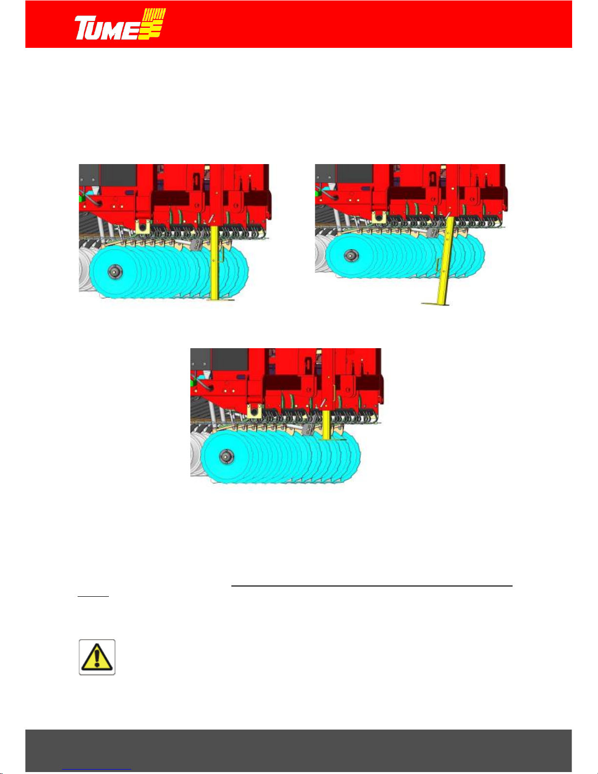
Support stand
The support stand in the machine front wall is used for storing and transporting the machine, see Figs. 1 and
2. The support stand is raised during sowing, see Fig. 3.
Figure 1. Support stand during storage.
Figure 2. Support stand during vehicle
transport.
Figure 3. Support stand during sowing.
Running gear, adjustable joints and lift cylinders
The adjustable joints of the running gear are locked and immobilized with a loc king flat bar when ever the
machine is being loaded or transported. When commissioning the machine, remove the flat bar and re-install
it so that the pins protrude through the elongated slots. The running gear can then be adjusted to
the
unevenness of the terra in, s ee Fig. 4. The machine should not be used with its back level locked into a rigid
position! Check that the lift cylinder locking taps are open, see Figs. 38–39.
If the machine must for any reason be used with the back level lock ed in a rigid position, s pecial c are m ust
be taken when driving over uneven terrain. Severe loads will be applied on the back level and individual tires!
Caution!
The machine must not be used without adjustable joint flat bars. These must always be
installed during use.
Page 8

8
Figure 4. Adjustable joint restriction and
locking bar.
Figure 5. Ground wheel in vehicle
transport position.
Using the ground wheel
The wheel which the machine uses for power transmission, the ground wheel, is positioned as shown i n Fi g.
5 for certai n vehicle transport m ovements. Retract the wheel and remove the transport supp ort from the
container seam. Turn wheel as in figure 15.
Tow bar alternatives and bar installation
Tume JC machines are supplied as standard with a common lowe r si de ba r , with which the machine can be
towed from a tractor tow-hook or agricultura l towing device. Standard de liver y also includes a tow-triangle,
see Fig. 6. A tow-triangle is attached to a 3-point lifting device on the tractor (category 2). A tow-bar is usually
packed to the back of the machine at the original manufacturer. Smaller parts are packed in containers.
Alternatively, an adjustable multi-function shaft m ay be s elected f or the m achine , which c an be used eith er
as an ordinary bottom-mounted side shaft, s uc h as with the Tume CultiPack c ultiv ator . A tow-triangle is not
provided with the multi-function shaft.
Upper support for the seed dr ill tow-bar is provided either by a mechanical push-bar (provided as standard)
or by a hydraulic push-bar (optional). The hydraulic push-bar allows the front part of the machine to be lifted
up, regardless of whether the tow-bar is connected to the pull-hook of a tractor, agricultural towing device or
optional roller.
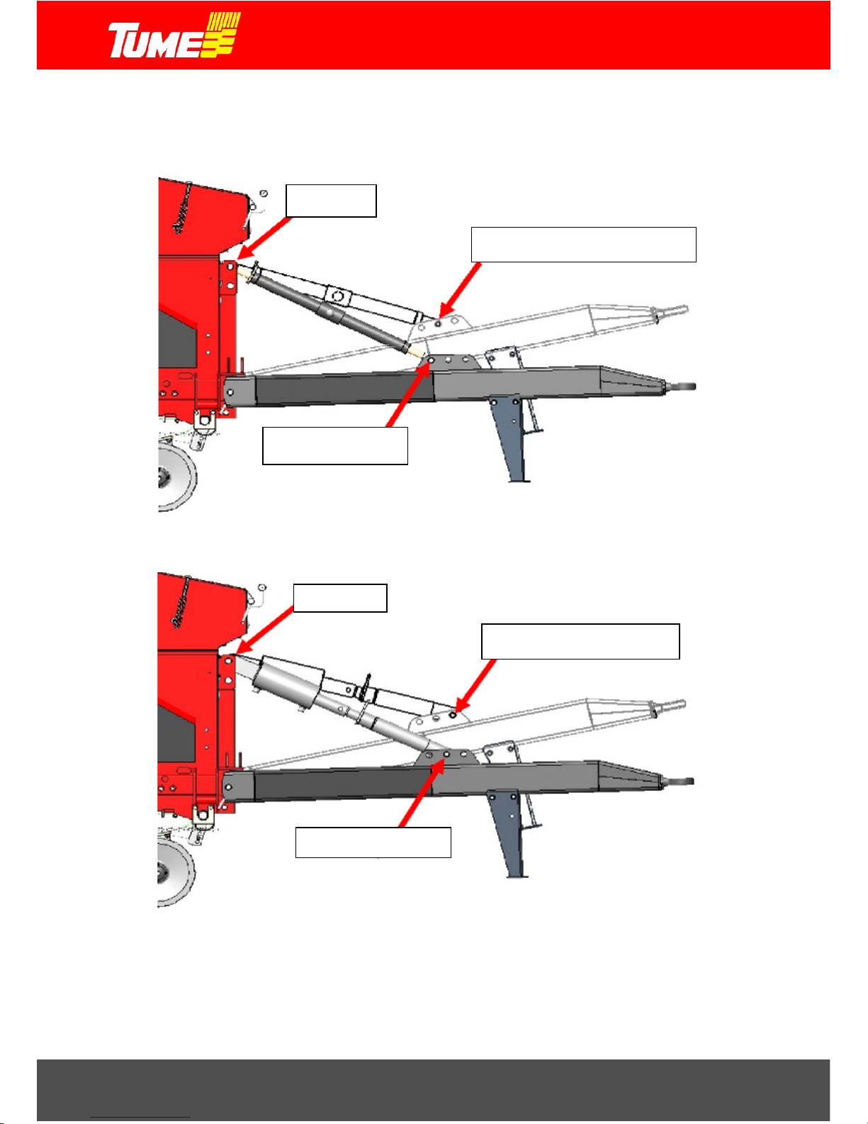
The bottom side tow-bar with tow-triangle is assembled according to Fig. 6. Fig. 7 shows the tow-bar
connection to the machine, when upper support is provided by a mechanical push-bar and the m achine is
connected to a tractor tow-hook or tow-triangle. Fig. 8 shows an as sem bly with a hydraulic push-bar. Here,
the machine is connected t o wheel packer. Note the position of the shaft pin in the upper and lower
shaft positions.
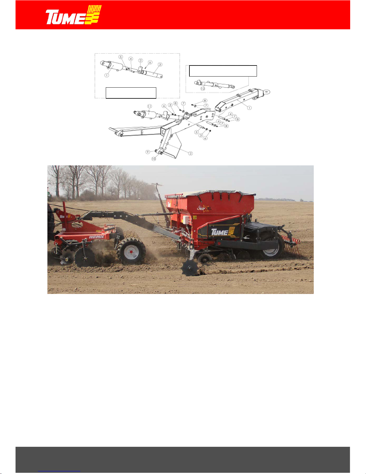
A multi-function tow-bar concept is shown in Fig. 9. Installation with mechanical push-bar is depicted in figure
10. The installation for the hydraulic push-bar is shown in Fig. 11.
Page 9

9
Figure 6. Standard tow-bar assembly.
The towing device is attached to the machine frame side brackets. The push-bar (hy draulic or mechanical)
in the picture is connected to the upper holes of the bracket on the front of the hopper.
Hydraulic lines and electrical wires are pulled through the tow-bar and attached to hanging hooks on the towbar. The hydraulic push-bar (optional) tube is connected to its own, one-way hydraulic valve.
Once the hydraulic line layout is com pleted, these sh ould be fixed in posit ion by bending the line supports
so that the lines remain in place.
Adjust the push-bar working dimension so that the machine is horizontal when calculated in terms of working
depth and attached to the tow-point at working height (tractor tow-hook, tow-bars in working position,
intermediate cultivat or towing point, etc.). Ensure th at the push-bar cylinder is in its retrac ted posi tion whe n
carrying out this adj ustment. Fine t uning of the towing device can be perfor med in the f ield, under sowing
conditions.
tow link
tow triangle
mechanical push-bar
drawbar cylinder
Page 10
10
5. Drawbar install ation
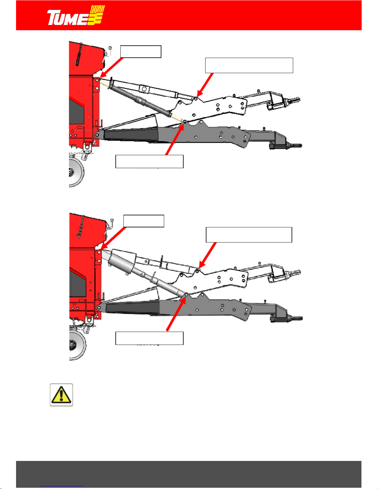
Figure 7. Standard tow-bar and turnbuckle.
Figure 8. Standard tow-bar and tow-bar cylinder.
upper hole
upper hole
for use with wheel packer
for use with wheel packer
for use with tractor
for use with tractor
Page 11
11
Figure 7. Multi-function shaft assembly.
drawbar cylinder
mechanical push-bar
Page 12
12
Figure 10. Multi-function tow-bar and turnbuckle.
Figure 11. Multi-function tow-bar and tow-bar cylinder.
WARNING - DANGER!
Never over-extend the push-bar, as this m ay reach the outer limit of the adjustment
range and the push-bar will bend or break. In a worst-case scenario, the person
performing the adjustment may then become trapped under a tilting machine.
Note that there are no restrictors on the helical bars of the push-bar preventing
adjustment beyond the permissible range. The portion of exposed thread must always
be less that the amount of thread within the inserted thread! Become acquainted with
the adjustment range measurements provided in this instruction manual, Figs. 12 and
13.
upper hole
upper hole
for use with tractor
for use with tractor
for use with wheel packer
for use with wheel packer
Page 13

13
Machine connection to tractor
Tow-bar alternatives and bar connections
Standard tow-bar
The JC seed drill is usually attached to a tractor tow hitch, agricultural towing device or to the towing point of
an optional roller (middle wheel packer).
The bottom standard tow-bar also comes with a tow-triangle, with which the JC can be towed from a tractor
3-point lift device.
WARNING!
When using a tow-triangle connection, special attention must be paid to tractor front
end weighting in order to maintain contr ollability. When the JC is connected to a tractor
tow-bar with a tow-triangle, the machine containers must be empty during transport. In
addition, ensure that the steering fro nt axle bears at lea st 20% of the tractor’s mass
(use additional weights), and that the tractor’s right and left side brakes are
interconnected.
WARNING!
The tow-triangle must be connected in as ve rtical a position as possible. Adjust to the
correct position using the tractor tow-bar. Never r aise or low er the tow-triangle to an
unnecessary height. Ensure that the tow-bar angle is not excessive wh en v iew ed from
side-on. The maximu m permis sible angle to the horizontal is +/- 9
°. Excessivel y sharp
angles can destroy the tow-triangle or tow-link.
Multi-function tow-bar
If a multi-function tow-bar is selected for the JC, the machine can usually be connected as normal to a tractor
tow-hook or agricultural towing device (with the bar installed as a lower tow-bar, see Fig . 10,11) or also to
higher-mounted tow-points. A bar set as an upper tow-bar is depicted in Figures 10 and 11. The upper towbar can for example be connected to the towing point of a Tume CultiPack intermediate cultivator.
WARNING!
The upper tow-bar must never be connected to a tractor push-bar bracket or other such
tow-point that is located above the rear axle of the tractor.
When using the upper tow-bar with a milling cutter or other lifting device fitting cutter,
it must be ensured that the tractor remains controllable even when the cutter is lifted
such that it is supported by the lifting device. In road traffic, the steering front axle must
for safety reasons have an adequate weighting of at least 20% of the tractor’s total
mass. Use additional weights if needed. Move the machine as necessary only with
empty containers!
WARNING!
Check all tow-bar parts for wear and other problems regularly! Pay special attention to
the tow-bar l ink and tow-bar c onnection pin and overall wear. Damaged or dangerously
worn parts must be replaced or repaired without delay.
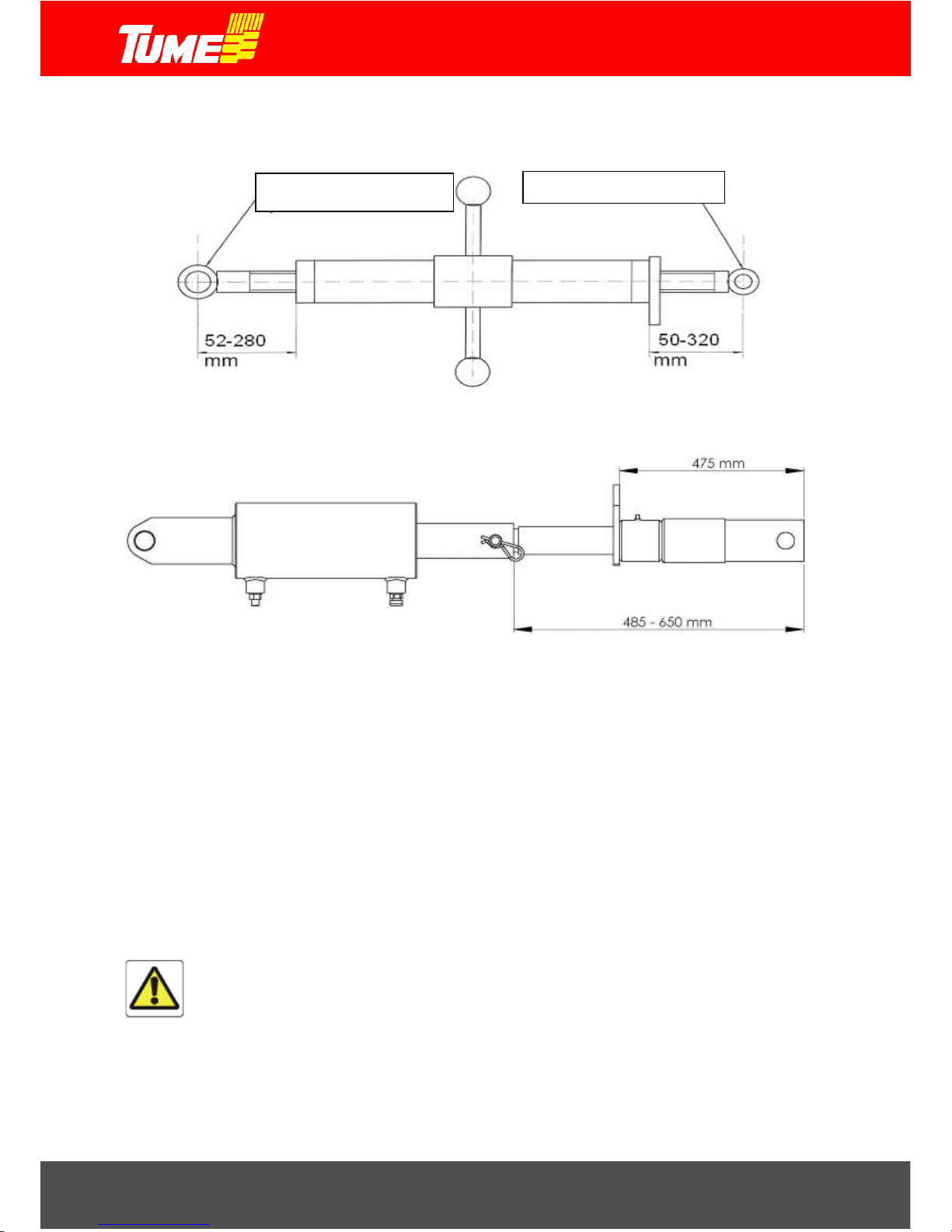
Length adjustment ranges of push-bars supplied with tow-bars
Caution! Follow the instructions provided for length adjustment ranges! Incorrect adjustment can
lead to serious personal injury or equipment damage.
Fig. 12 shows the length adjustment range of a mechanical push-bar provided as standard equipment. Note,
that the area is not symmetrical. Pay separate attention to the measurement adjustment of each end!
Page 14
14
Lock the push-bar with the thread locking pin. Fig. 13 shows the equivalent hydraulic push-bar
measurements.
Figure 8. Length adjustment areas for mechanical push-bar.
Figure 13. Length adjustment areas for hydraulic push-bar with adjustment sleeve.
Connecting hydraulics
Standard JC hydraul ic equipment is connected to a hydraulic outlet intended for external singlefunction cylinders. Bar cylinders supplied as optional equipment require a second single-function
outlet.
If the seed drill is installed with dual-function lift cylinder equipped markers, the two hoses running
from machine are connected to the tractor’s dual-function outlet. Similarly, the hydraulic push-bar of
a multi-function tow-bar (optional) is dual-function, and therefore requires another 2-function outlet.
NOTE! When connecting hydraulic connectors, the tractor’s hydraulic PTO control gear must
be in the lowering or floating position to ease the connection.
WARNING!
When connecting hydraulic lines to the tractor, ensure that the machine, tow-bar or
markers cannot low er uncontrollably and thus harm adjacent people or other objects!
Connect the tow-bar to the tow-point before connecting the hydraulics.
NOTE! Certain tractor models require the use of non-standard hydraulic quick-change
connectors recommended by the tractor manufacturer. Replace the relevant components with
suitable components as required on your tractor in order to ensure proper hydraulic function.
HOPPER END
TOW-BAR END
Page 15

15
Caution! Before starti ng sowing, the relat ive position of coulters and harrow tines to each
other must be ensured with a tow test. This can be carried out in a field or in sof t sand. E ac h
fertilizer coulter m ust always travel at a distanc e half-way betwe en two seed coulters under
direct tow. The gap b etween seed coulters must be approx imately 125 m m, and the harrow
tines must travel bet ween the seed rows. Mo ve the coulters and tines laterally a s required.
This check must be performed at least once per usage period.
Driving instructi ons
Driving instructions for transport
The machine is kept in its upper position by means of the tractor hydraulic valve. For this reason, it must be
ensured during any transport that there ar e no leaks in the trac tor hydraulics, and that the hydraulic lever
controlling the raising or l owering of the m achine is not m oved accidentally. Kee p the lift cylinder safety
taps open during transport as well as during sowing, see Fig. 39.
During transport, the maximum permissible speed is 30 km/h. See general safet y instruc tio ns , Section 2.
Driving instructions for sowing work
If the ground wheel is i n its raised p osition with the tra nsport supp ort (Fig. 5), lower it to its usage pos ition,
see Fig. 14.
Caution! Always move forward when lowering the machine. Otherwise the coulter arms
may become damaged or the coulters may become clogged.
Avoid unnecessar y driving in the sown are a. Select a drivin g technique t hat ensur es that onl y minimal tire
tracks are left in the s own area. It is usually good to start seed ing on the basis of a single block, s o that
sufficiently wide tracks can be generated (usuall y 1-2 ti mes the width of prot ective plant spr aying). Sowing
is then performed back and forth, driving in the direction of the longest side of the block.
Caution! Try wherever possible not to sow the corners of the block in a circular motion,
and raise the machin e at corners. Making steep turns with the machine and coulters
on the ground will cause unnecessary wear to the machine tow-bar and coulters!
All-around sowing is used on irregul ar block s. Lift t he m achine at all corners! Only sow in a gentle circle in
the ground on clearly wide cor ners!
Because of the hydraulic structures, the machine must always be lifted all the way to its upper position. Only
then ca n the machine b e lowered again. Co nversely, when lowering the machine, the l ower position m ust
be reached before the machine can be raised again. When sowing, care must be taken not to lift the machine,
as it cannot be lo wered b ack to its cor rect wor k ing depth u nless i t is fir st raised h igh enough that the depth
control valve (Fig. 31) is reopened.
Fig. 31 shows the valve controlling raising and lowering, moving with the wheel support arm. When the valve
lever r eaches the up and down pos itions of the guiding pins, the valve cl oses and the lif ting or lowerin g
motion is stopped.
Ensure that the harrow is raised sufficiently when lifting the machine. See Section 16, adjusting the harrow.
Caution! Never reverse when the harrow tines are in contact the ground. Similarly, do
not reverse into contact with the earth formation at a field edge or other obstacles.
The machine must be able to work on even terrain in a horizontal position. See Section 14, fertilizer
application depth adj ustment. If the m ac hine is ang le d f or ward as it moves (this can happen if to wed i n any
other way than with the tow-triangle) the towing device push-bar must be extended. If the machine is angled
backwards as it m oved, the push-bar mus t be shorten ed. Note the push-bar adjustment area ! C heck the
Page 16

16
fertilizer and sowing depths after driving f or a certain time. Check the adjus tment of the markers (optional)
by also studying the sowing seam area.
Caution! Only lift and lower the machine when it is moving forward. Never reverse the
machine when the coulters are in the ground and power transmission is connected.
Check periodically for dr ill blockages. Also check the state of all seed an d fertilizer lines and clear any
blockages.
At the start of so wing, check the area that can be sown with a single container. You will then be able to
determine the next estimated filling time based on the area surface.
Keep sufficient amounts of seeds and fertilizer in the container. Particular attention must be paid to this due
to the design of the bottom, especially at the start.
Do not store fertilizer or seeds in containers for several days, especially in moist weather. Damp fertilizer can
lead to feeding problems.
Optimal seeding results are achie ved at driving speeds of 7-10 km /h. In rocky conditions, the driving
speed must be reduced to suit the circumstances.
The maximum sowing speed with small and regular-sized seeds under good conditions is 15 km/h;
that for sowing peas and beans is 6-7 km/h.
6. Feeding equipment ground wheel
The feeding equipment receives the power to drive it from the ground wheel on the right side of the machine.
The ground wheel is mounted on the container and is therefore lifted when the machine itself is lifted. When
the machine is lifted, the ground-wheel is no longer in contact with the ground and it stops providin g po wer .
A separate power transmission clutch is therefore not required.
Caution! Do not rotate the ground-wheel to reverse direction! Always raise the machine
before reversing the tractor. Both coulters and the ground-wheel must be clearl y off
the ground.
Figure 14. Ground-wheel in work position. Figure 15. Ground-wheel in transport
position.
Page 17

17
7. Filling the container
Using the tarpaulin covers
The drill is equip ped with tarpaulin co vers that can be rolled open with cranks located at its front and rear
edges, see Figs. 16–17. When filling the fertilizer container, you need only open the front part of the tarpaulin
cover, and simila rly, when filling the s eed container, on ly open its back part. T his will prevent m ixing up the
fertilizers and seeds when filling the containers. During transport and sowing, the tarpaulin cover should
preferably b e kept closed and he ld in po sition w ith rubber mounts. This will avoid im purities penetratin g the
containers and securing the cover in position.
Caution! On machines equipped with markers, the front edge crank must compulsorily
be mounted whenever working with rubber holders, see Fig. 16. Otherwise, the crank can
come into contact with a marker arm, leading to the risk of damage.
Figure 16. Tarpaulin cover in work position. Figure 17. Tarpaulin cover in open position.
Use of sieves
Standard sieving equipment is normally fitted to the fertilizer and seed containers of JC seed and fertilizer drills
(this may vary by country and market). These sieves prevent foreign objects from causing feeding
disturbances, or fertilizer crumbs etc. developing in the feeding equipment. The fertilizer sieve must always be
kept in place during container filling and seeding. The seed sieve must also be in place except in the event of
certain exceptions.
Such exceptions include large or elongated seed shapes, which may be too large to fall through the sieve. For
example, many types of oat cause problems, as the grains are long and li ght. If it is rea sonable t o susp ect
that the seeds will not be able to pass through the sieve, the sieves must be temporarily dismantled
and removed fr om the container. When filling or seeding without sieves, special attention must be paid
to ensure that no foreign objects enter the fe eding equipment, i.e. remnants of sack, tools etc.
Timing of the filling
When starting sowing, it is recommended that the machine be moved to the field in empty condition. Fertilizers
and seeds are delivered to the field, i.e. with a tr ai ler, and seed drill filling is car r ied out a t the s ide of the field
block. If the machine must be filled at a distance from the block to be sown, special caution must be exercised
during transport with full containers.
Caution! The maximum transport speed of 30 km/h may only be used on roads in good
condition, and containers must be empty! The maximum permissible driving speed with
full containers is 15 km/h ! On potholed, ro cky or e xtremely na rrow roads, the transport
speed must be adjusted downward according to circumstances.
Monitoring of container levels is possible:
Page 18

18
By looking into the container from time to time, when the machine must be stopped.
By observing the area meter of the machine, when the area size that can be sown with a full container
is clear and the meter reading for the last filling has been recorded.
With optional electronic monitoring equipment. Such devices issue an alert when a certain amount of
fertilizer or seed remains in the container.
WARNING!
Transporting an assisting person or other passengers on the steps of a moving
machine or elsewhere in the machine is strictly prohibited. The seed drill must be at a
standstill when leveling seeds or fertilizers in the containers!
Adjusting the fertilizer and seed container volumes
The position of the f ertilizer and seed container partition can be adj usted s o that the container volume ratios
can be changed. Such adjustments are c arried out by loosening the lock ing screws of the partition sup port
arms (Fig. 18) and moving the partition to the desired position. Remember to re-tighten the support arm locking
screws after making the adjustment. The partition adjustment area can be changed by moving the support arm
ends to other attachments pins (Fig. 18). When using the machine for sowing only, the partition can be moved
fully forward in order to maximize the seed space, see Fig. 19.
Caution! Carry out the adjustment when the containers are empty or nearly empty!
Figure 98. Partition support arm.
Figure 19. Seed container maximum volume
Maximum fill liters
Fertilizer (max)
Seed (min)
Seed (max)
HS/HST device decreases
seed volume
HKL 3000 JC Star XL
2360
1350
3320
330
HKL 4000 JC Star
2580
1580
3640
300
Filling method
The large size of the containers means that their filling level is also relatively high, a consideration if 40-50 kg
sacks must be lifted from ground level. For this reason we recommend working as follows: first place the sacks
on pallets, then raise these with a pallet lifter or front-loader truck forks to a suitable height for machine filling.
Jumbo sacks (500–1000 kg) can be handled with different loaders. Jumbo sacks must never be placed on the
seed drill structures. Do not overload the seed drill. Identify methods for partiall y emptying a jumbo sack.
Page 19

19
WARNING!
When filling the machine, never pass under a load which is suspended from a loader
or otherwise lifted, or under the lifting structure.
When using loose f ertilizer and/or s eeds, we recomm end the use of a high-tipp ing t railer or f ill-screw. When
using a tipping trailer, the tipping point must be selected wit h care in order to prevent the carriage
from overturning. As the JC support wheels and harrow are located at the rear of the machine, certain filling
carriages may not have sufficient reach. The containers can then be filled f rom the side of the machine as
required.
8. Emptying containers
Emptying the fertilizer container
The fertilizer container is emptied through the coulters or by using the test seed troughs.
If the seed container is not fully emptied, care must be exercised to prevent seeds from falling into the
fertilizer. For this r eason, remove the seed feeding cassette (see Figs. 22 and 23) when the see d
feeding does not rotate by means of the ground-wheel or by rotating the fertilizer shaft.
Set the load cover under the machine.
Set the fertilizer feed to the maximum feed amount.
Lift the fertilizer si de feeding equi pment lever for the bottom flaps ov er the scale (Figs. 26 and 28).
The container will then empty almost completely.
Guide the remaining fertilizer, e.g. with a brush, to the feed chambers. Rotate the feeding device with
the ground-wheel a number of tim es, see Fig. 29, until the chambers are empty. Then, swing the
bottom flaps back and forth fast with the adjustment lever until the last fertilizer grains fall out through
the coulters.
Pull the cover out f rom underneath, and ins tall the seed sid e feedin g equipm ent po wer transm ission
cassette back in the original manner.
Emptying the seed container
The feed container can be emptied through the coulters or using the test seeding troughs.
Empty through the coulters, i.e. the load cover is spread underneath the coulters.
Adjust the feeder to the maximum feed amount during the emptying process.
The seed container is emptied by lowering the bottom flap crank fully over the scale (Figs. 20 and 24).
Guide the remaining s eeds into the feed chambers.
Rotate the feed equipment a few times so that the seeds remaining on the feed rollers flow downward.
Note that when rotating the f eeder , some of the fertilizer m a y flow on top of the lo ad c over u nles s the
fertilizer container has been emptied beforehand, or unless the fertilizer feed shaft has been rendered
inoperable with a ring pin (Fig. 27).
Swing the bottom flaps fast with the crank a few times so that no seeds are left on top of the flaps.
The containers can be emptied using the test seeding troughs if only small amounts of seed and
fertilizer remain in the containers. Use of the test seeding troughs is described in Section 12.
The method for emptying is essentially as described above. If large amounts of seed remain in the containers,
the bottom flap crank must be closed when emptying the troughs.
WARNING!
If compressed air is used to clean the containers, remember to use adequate protection
to prevent pollen dust, seed treatment, etc. from penetrating the respirator y system an d
eyes!
Page 20

20
9. Seed feeding equipm ent and adjustment s
Overview
JC seed drills use a groove feed on both the fer tilizer and seed sides. The feeding bodies are called feed
rollers. Under the feed rollers, you can find adjustable bottom flaps with springs, with closing covers on top of
them, see Fig. 20. The f eed chambers are locate d at the bottom of the containers. In practice, this solutio n
provides independence in term s of sowing amounts, despite any til ting of the seed dril l from side to s ide, or
the driving direction. The feeding equipment is manufactured of corrosion-resistant materials. The bottom flap
adjustment lever under the feed rollers is in the cente r of the rear of the m achine, see Figs. 2 0 and 24. For
sowing small seeds, the power transmission ratio can be adjusted by turning the power transmission cassette,
see Figs. 22 and 23.
Figure 20. Structure of seed feeding equipment.
The f eed amount can be changed by adjusti ng the feed rollers mounted on the feeding shaft sideways in
relation to the feed c ham bers, such that this c hanges t he effec tive width of the f eed roller s. Adjustm ents are
made on the left side of the machine with a hand-wheel, see Fig. 21.
Figure 21. Feed adjustment hand-wheel.
Page 21

21
The hand-wheel is lock ed with a plas t ic le ver on which is also marked the main feed scale, 0-10. T he i nterval
between numbers equals a single rotation of the hand-wheel. The outside of the hand-wheel is m arked with
10 locking doors, labeled 0-9. Using these allows 100 dif ferent adjustment positions to be genera ted. W ith
small seed transmission (cassette position II, see Fig. 23) 100 feeding adjustment positions can be generated
in the same way from the sm aller rotation num ber area. T he m ain sc ale value is read f rom the inner edg e of
the hand-wheel.
Rotating the hand-wheel counter-clockwise increases the feed. When the des ired seed sowing amount is
known from the sowing table located inside the machine cover (or from this manual, see Fig. 25), the instructed
feeding adjustment pos ition can then be seen, see Section 11. Note the used power transmiss ion cassette
position, see Figs. 22 and 23.
The hand-wheel should always be adjusted so that the desired adjustment position is always
approached from a greater adjustment position. If the original adjustment position is smaller than
desired, the hand-wheel should be rotated counter-clockwise 1/2-1 times beyond the intended
adjustment, and then rotated backwards to the desired adjustment position.
After this, the adj ustment locking le ver is i nserted i nto a notch on t he hand-wheel, which then lock s both the
wheel and lever. Note that the adjustment position given in the seeding table is for reference only - the actual
feed amount will change betwee n different seed b atches. In order to determine actual feed amounts and
obtain an objectiv e value, you should always perform a calibration or field test, see Sections 12-13
below.
If dirt accumulates on the feeding devic e or seed characteristics change, i.e. be cause of the seed dressing
function, the actual feed a mount may change significantly from its original value. We recommend c leaning a s
needed, but at least on a daily basis. Rollers can be cleane d by adjusting th e feed amount to zero and then
again to the desir ed a djustm ent val ue. In such cases t he pr evious ly stat ed adj ust m ent rule sh ould be k ept i n
mind - i.e. rotate first 1/2-1 times beyond the desired adjustment value. The real feed amount can be checked
by repeating the calibration test.
C
AUTION! THE Hand-wheel must not be forced to a zero-position. Simultaneous rotation of
the feeding axis will ease the adjustment.
C
AUTION! the maximum speed when sowing large seeds such as peas and beans is 6-7
km/h. Ensure that the seed tubes do not become blocked. Blockages can cause damage
to the tramline device.
Seed feeding device speed range selection using the power transmission cassette
The rotation speed of JC seed dri ll seed feeding devi ces in relation to the drivin g speed can be selected b y
rotating the power transmission cassette. Setting I shown in Fig. 22, where the word ”GRAIN” is on the visible
side, provides a higher rotation speed, which is suitable for sowing normal-sized seeds. Rotating the cassette,
see Fig. 23, achieves 80–90% slower speed II, suitable for small seed sowing.
Figure 22. Power transmissi on cass et te
I = GRAIN.
Figure 23. II = SMALL SEED.
Page 22

22
Rotating the power transmission cassette between positions I and II
See Figs. 22 and 23. Remove the ring pins and pull the cassette from its shaft. Rotate the cassette
so that it is in a backward positio n to the same cassette sle eves, with a different side exposed.
Never turn the cassette upside down, i.e. so that the shaft and cassette sleeves switch places. The
selected setting (I or II) is marked on the visible side of the cassette cov er. The position shown in
Fig. 23 allows very small seed amounts, i.e. rapeseed 5 kg/ha, to be sown.
Bottom flaps
Feed accuracy is dependent on the appropriate di stance between the bottom fla p and roll er feeder .
It is important that the bottom flaps are in the correct position, and that they are not adjusted
following a calibration test without repeating the calibration test. Bottom flaps are flexible, in case
any external foreign object protrudes between the bottom flap and feed roller.
Figure 24. Bottom flap adjustment lever, seed.
Adjustment position 4 of the bottom f laps is used only when seeding es pecially lar ge seeds (e. g. certain
canned peas). Note that in position 4 the f eed amount increases when drivin g uph il l.
Caution! The seed can flow out of the container freely when the bottom flap lever is
moved below past the scale.
10. Fertilizer feeding equipment and adjustments
Overview
On the m achine, fertilizer feed chambers make up half the number of the see d feed chambers. Feed
amount adjustments are made by turni ng the feed r ollers mounted on the ferti lizer feed axis s ideways in
relation to the feed c hambers. Adjustment s are made using a hand-wheel on the left side of the machine.
Electrical adjustment is also available as an option.
The feed chambers are located at the bottom of the containers. This solution provides an almost standard
seed amount despite any tilting of the s eed drill from s ide to side, or the dri ving direction. The feed is a
groove-feed type, in which the feed bodies are called feed rollers, see Fig. 28. The feed rollers are equipped
with a helica l thread and are made of plastic. The bottom f laps under the f eed rollers are adj ustable, b y
means of an adjustment lever in the center of the front end of the machine, see Fig. 26. The entire fertilizer
feeding machine is manufactured of corrosion-resistant materials. The fertilizer container enables the
application of all types of granular f ertilizer. The use of powder ed fertilizers should be av oided. A mix ing
shaft is available as an option.
Adjustment instructions for the bottom flap
adjustment lever:
Seed type Adjustment
Small seeds, i.e. rapeseed
Slot 1
Ordinary seeds, grain
Slot 2
Large seeds, i.e. pea
Slot 3
Particularly large seeds
Slot 3 - 4
Granular fertilizer
Slot 2
Page 23

23
Figure 25. Seeding table and usage examples.
Page 24

24
Fertilizer feed amount adjustment
The feed amount is adjus ted using the hand-wheel on the left side of the m achine (Fig. 21). The handwheel is locked with a plastic com ponent on whic h can also be found the main feed scale. The feed value
is read from the part of the scale that is on the inner edge of the hand-wheel. Decimal-step feed adjustment
can be read from the scale on the hand-wheel cover, which is located at the locking lever slots.
The hand-wheel adj ustment range is 10 rotations, with ten loc king slots on the wheel cir cumference for
each rotation. This means that the feed has 100 different adjustment values.
Caution! In order to adjust the feed, the plastic main scale lever must be pr essed
towards the machine side in the direction of the arrow and pressed inw ard so as to
rotate 90 degrees forward when releasing the hand-wheel lock.
After adjustment, the lever should be returned to its locked position in the
handwheel slot.
Rotating the hand-wheel counter-clockwise increases the feed. When the desired fertilizer sowing amount
is known, the sowing tabl e located inside the machine or the so wing table in this m anual, see Fig. 25,
provides a rated feeding adjustment position.
The hand-wheel should al wa ys be adjus t ed s o that t he des ired a dj us tment position is alwa ys appro ac hed
from a greater adjus tment position. If the original adj ustment position is smaller than des ired, the handwheel should be rotate d c o unter -c lock wise 1/2-1 times beyond the inten ded adj ustment, and then rot ate d
backwards to the desired adjustment position.
After this, the adjustm ent locking lever is ins erted into a notc h on the hand-wheel, which then lock s both
the wheel and lever. Note that the adjustment position given in the seeding table is for reference only - the
actual feed amount will change bet ween diff erent seed batch es. A calibration test must be carr ied out in
order to determine the actual feed amount.
Figure 26. Bottom flap adjustment lever,
fertilizer.
Figure 27. Fertilizer feed chain wheel.
The nor mal positio n of the bottom flap is slot 2. Slot 1 can also be use d for ver y small grained fertilizers
(granular size 1-2.5 mm).
Caution! The fertiliz er may flow out of the container if the bottom flap adjustment
lever is moved past slot 2 on the scale.
If moist fertilizer enters the feeding dev ice, the feed rollers can b ecome blocked. Certa in fertilizer types
may also tend to become sticky. This can significantly impact the feed amount.
Page 25

25
Feed rollers can be cleaned by adju sting the feed amount to zero and again back to the desired adjustment
value. In this case, remember the adjustment rule above; first rotate 1/2-1 times past the desired value and
after this back to the corr ect value. Seed tabl e instructions and calibration test perform ance instructions
are given below.
The fertilizer feeding device can be turned off by removing the ring pin from the fertili zer feed shaft
end on the right side of the machine, see Fig. 27.
Figure 28. Fertilizer feeding device.
11. Sowing table examples
General
The sowing table sho wn in Figure 25 gi ves three different use sowing examples.
Note that the sowing amount indicated in the sowing table is for reference only. The actual sowing amount
will depend on the characteristics of the seed used, whi ch will vary significantly based on year and type.
Sowing amounts must be check ed with a calibration tes t, the performance of which is explained later in
Sections 12 and 13.
Seed feed adjustment example for sowing grain
Case 1 To sow oats at 215 kg/ha
The correct bottom flap lev er adj ustment position is noted i n the sowing table. The slot position is
”2”
Select the label "oats"
The machine power transmission cassette is set to "I"
Start from the left margin table along the line 215 kg/ha
Move horizontally to the part where the line crosses the descriptor "oats"
From the intersection, proceed directly down to the lowest scale. The adjustment value is 6.9, and therefore
between 6 and 7 on the main scale. Slot ”9” should then be selected on the circumference scale. Lock this
to 6.9.
Page 26

26
Adjustment example for sowing rapeseed
Case 2 To sow rapeseed at approx. 11 kg/ha
Note that the corr ect p ositi on of the bottom flaps is defined as "1 " in the upper ri ght cor ner of t he
sowing table
Review the small sowing table inserted into the upper left-hand corner of the table
Identify your starting point in the left margin of the small sowing table, at 11 kg/ha
Move horizontally to the right along the 11 kg/ha line to where it intersects with "rapeseed"
Move vertically down to the sub-scale, where it can be seen t hat the c orrec t adj ustm ent value o n
the main scale is "1”, and circumference "4". Then rotate the hand-wheel 1.4 times from zero
Note the l abel "transmis sion II” in the upper left-hand corner of the sm all sowing table. In power
transmission, the small seed setting must therefore be used, meaning that the cas sette m ust
be rotated so that transmission code "II" is visible, and the power transmission cassette is installed
according to Fig. 23, i.e. t he rotation speed is in the slo wer position, with the upper side of the
cassette connected to the shaft further behind.
Adjustment example, fertilizer side
Case 3 To sow NPK mixed fertilizer at 410 kg/ha
Note that the adjustment of the bottom flaps for granular fertilizer in the upper right-hand corner of
the sowing table is "2"
Start from the left margin of the large sowing table and move to "410 kg/ha"
Proceed horizontally along the 410 kg/ha line to the right to where this intersects with the line with
descriptor "granular fertilizer"
Move vertically down from the intersection to the lowest scale, where it can be seen that the main
scale reading set on t he adjustment wheel locking le ver should be "4". Similarly, the adj ustment
wheel adjustment value must be ”9”.
Caution! Calibration tests should be carried out after any adjust ments in order to
ensure the correct seed and fertilizer amounts. Calibration test rotation amounts
dependent on machine type can be seen in the upper left-hand corner of the sowing
table, in the "Calibration test" section.
12. Calibration test
General
As the adjustment val ues provided in t he sowing table ar e for reference only, a calibration t est must be
performed before starting sowing. Before starting the calibration test, the machine must be adjusted
according to the sowing table.
Caution! Dressed and undressed seeds may require completely different feed
adjustment values in order to achieve the desired feed value. If a seed dressing
device is used on the fertilizer drill, the correct feed adjustment must be ensured and
final adjustments should only be performed as r equired on the machine after the first
filling, once an approx. 2 000 m stretch h as been sown. Note also that different seed
dressing agents will also affect the feed amounts in different ways, and ca n have a
reducing effect of up to 20% compared to undressed se ed!
Ensure that dressing agents are not applied to seeds which are not meant to be
dressed. I.e. sprouti ng rapeseed deterio rates easily. In such cases, we recommen d
fully removing the dressing containers from the seed drill container.
Page 27

27
Before starting the calibration test, check:
The power transmission cassette setting, I or II (Figs. 22 and 23)
The position of the bottom flaps (seed and fertilizer)
The seed feed amount set on the hand-wheel
The fertilizer feed amount set on the hand-wheel
That the cover doors on both fertilizer and seed sides are fully open
That there is seed and fertilizer in the containers
That the tire track device is not active
The machine is slightl y lifted from the ground, meanin g that the feed equipment can be rotated with the
machine ground-wheel, see Fig. 29. Rotation is achie ved with a c rank pin located und er the co ver on the
right side of the machine. Note that the machine must be balanced horizontally.
Tume JC drills are fitted with calibration test troughs as standard on both the seed and fertilizer sides, see
Fig. 30. You can retain bot h troughs in position d uring sowing. Ho wever, always remember to empty the
troughs of dust etc before carrying out any calibration test.
The machine tubes (for both seed and fertilizer) must be set to the calibration test position simultaneously.
This is done using the handle on the right side of the machine, see Fig. 30 position A.
The calibration test can be carried out in 3 different ways:
Simultaneously for both the seed and fertilizer, when the power transmission is in sowing position,
in other words the ring pin on the fertilizer feed shaft is in the inner hole, see Fig. 27.
Separately for seed , then the r ing pi n is rem oved from fertilizer shaf t, see Fig. 27. Remember to
put it back.
Separately for fertilizer, in whic h case th e ring pin is i n the inner hole, see Fig. 2 7, and the power
transmission cassette is removed, see Fig. 30. Remember to replace the cassette following the
calibration test.
Figure 29. Calibration test.
Page 28

28
Figure 30. Using the seed side calibration test system
Simultaneous calibration test for fertilizer and seed.
Place the machine tubes in the calibration test position. Rotate the crank a few times in order to fill the feed
chambers. Then check that each feeding de vice contains seed and f ertilizer. Following this, empty the
calibration test trough carefully.
Rotate the crank the number of times mentioned for the machine type in question in the sowing table. The
sowing table can be foun d on the inner surf ace of the lef t side of the m achine. The rotation speed m ust
correspond approximately to the driving speed used.
Weigh the seed and fertili zer that has entered the test sowing troughs. If the calibration test was carried
out with a number of rounds equivalent to an acre (reference number is given in table), the sowing amount
per hectare can be determined by multiplying the weighing results by 100.
The obtained results may differ from the desired results because of ordinary variations in fertilizer and seed
batches:
If the results obtained differ excessively from the desired f eed res ults , the feed am ount s must be
made more accurate by rotating the hand-wheel
The feed adjustment must be increased or reduced by as many percentage points as the weighed
calibration test amount exceeded or fell below the desired level
The above can be presented as follows:
Desired feed amount
New feed adjustment value = x (present adjustment value)
Observed feed amount
If we then insert sample figures into the formula above:
Desired fertilizer feed amount = 650 kg/ha
Feed amount based on calibration test = 600 kg/ha
Hand-wheel adjustment used in calibration test = 6.5
Corrected value according to formula = (650/600) x 6.5 = 7.0
Caution! The given calculation formula is intended to simplify the determination of
correct adjustment. The end result must however always be checked with a
calibration or field test if an accurate end-result is desired!
Caution! The calculation example given above is for reference only, and is only
intended to demonstrate the use of the calculation formula.
Page 29

29
After performing the calibration test and adjustments, r emember to return the funnel shelves to so wing
position B, see Fig. 30. Also remember to replace the crank pin in position and close the protective covers.
Performing the fertilizer side calibration test:
Remove the power transmission cassette, see Fig. 22.
Check that the fertilizer side bottom flaps are adjusted to the correct position, usually slot 2
Check, that all closing doors are open. Open these if necessary
Select the desired feed amount from the sowing table by adjusting the hand-wheel
Rotate the ground-wheel several times so that the fertilizer chambers fill and the fertilizer feed from
the test sowing chambers stabilises
Set an empty, clean calibration test trough in position
Perform a calibration tes t by rotating the gro und-wheel the number of times stated in the sowing
table
Weigh the fertilizer collected in the trough. Use an accurate scale!
If the result does not match the desired feed amount, correct the adjustment with the hand-wheel.
Familiarize yourself with the method given for calculating probable corrections.
Perform a new calibration test to ensure that the feed amount is correct.
Remove the crank pin and return it to its position in the right side cover
Return the power transmission cassette to its position
If the machine is equipped with an TC+ on-board computer providing fertilizer remote control,
please refer to the additional instructions in the TC manual.
Clean the fertilizer side feed rollers by occasionally rotating the hand-wheel so that the feed is fully
closed. This will enable you to ensure correct feed amounts during calibration tests and during
actual sowing.
When returning the feed ad jus tment bac k t o the value in pr actic e or o ther wise c ha nging the feed
amount, always approach the desired adjustment value from the same direction.
Carrying out a calibration test only on the seed side
It is quite normal to perform the fertilizer side calibration tes t less often than the seed s ide test. For the
duration of the seed-side only calibration test, the power transmission to the fertilizer side should be
switched to idle so that no fertilizer is wasted, see Fig. 27. The fertilizer side is switched to idle by removing
the ring pin shown in the figure.
Caution! If you perform a seed side calibration only and for this reason remove the
pin from the chain-wheel located on the fertilizer shaft, BE SURE TO REMEMBER
TO REPLACE THE PIN IN POSITION BEFORE STARTING SOWING.
FORGETFULNESS WILL HINDER THE FULL FUNCTION OF THE FERTILIZER
FEED!
Instructions for improving sowing accuracy
Calibration test values given in the sowing table are for reference only. Their accuracy depends on ground
quality, cultivation depth, tire pressure, and tire manufacturing tolerances.
The sowing accuracy can be however improved by doing a tow test under sowing conditions. The tow test
is performed by towing the m achine over the distanc e require d to sow one acr e under sowing cond itions
and by simultaneously reducing the ground-wheel rotations. Record the value obtained and use this when
carrying out calibration tests.
If the value measured differs widely from the seeding table value, carry out a new test. In the table below,
the distance W used in the tow test refers to differ ent working widths, eac h matchin g a one-acre s owing
area:
L = 33.3 m when working width = 3.0 m
L = 25.0 m when working width = 4.0 m
Check the area meter accuracy when performing the measurement.
Page 30

30
13. Field test
Field tests are by far the most secure testing method for feed amounts. Performing a field test on a field to
be sown as well as on an already upturned seed bed establishes conditions which matc h sowing very
accurately. Field tests c an be performed for both the seed and fertilizer.
To perform the field test:
Adjust the machine and configure it according to instructions
Measure the driving distance required to sow one acre, dependent on the machine type:
JC 3000
33.3 m
JC 4000
25.0 m
Drive outside of the tes t le n gth f or approx. 10 meters with the machine in working position so th at
each feed chamber is sowing seeds
Empty the contents of the test sowing trough into the container
Drive the distance in accordance with the sowing table above with the machine lowered to sowing
position
Weigh the seeds in the tes t sowing trough. Multiply the weighing results by 100 to obtain the
amount of seed in kg/ha
If tuning adjustments are required, perform the calibration test as described
If the machine is equipped with TC, make sure that the tir e track function is not switched on while
carrying out the test!
14. Fertilizer application depth adj ustment
Overview
The fertilizer application depth can be adjus ted stepless, fr om surf ace application to a depth of approx. 8
cm. Ordinary fertilizer depth for grain plants is 6-7 cm. The depth can be adjusted by changing the closing
moment of the hydraulic valve on the tire support arm, see Fig. 31, and by modifying the length of the towbar push-bar using the adj ustment screw, so that the machine alwa ys travels in a horizontall y balanced
manner in the direction of travel.
Figure 31. Fertilizer depth adjustment.
Page 31

31
Changing the place of pin 1, see Fi g. 31, will produce a ch ange in closing m om ent. The scal e above the
slot, 10-5-0, is equi valent t o t h e a pp licat io n d ept h i n centimeters. Pin 2 lim its the machine lifting heigh t by
closing the valve when the machine is lifted high enough.
The tow-bar (meaning the tractor tow-bar he ight) is adjusted so that the machine travels in its sowing
position horizontally. The length of the towing device push-bar can also be adjusted. If the m achine is
equipped with a tow-bar with a h ydraulic push-bar (recommended, for ex ample with rollers), t his can be
used to adjust the fertilizer depth. The cylinder in question is actuated by a separate hydraulic valve on the
tractor. This function is in completely independent of the machine’s raising/lower i ng cir cuit. Increasing the
push-bar length raises the fertilizer coulters correspondingly. Adjustments of this kind can be n ecessary,
for example on soft ground. It is recommended not to raise the roller, but rather to adjust it using the pushbar.
Adjusting the fertilizer application depth
Adjustments must be per formed in the fie ld or on sof t ground in order to enable the fertilizer coulters t o
press into the ground. A dj u s t pin 1, see Fig. 31, and center this on the desir e d p l acement level (along the
10-5-0 cm scale).
Lower the machine while driving forward. Stop the tractor once the machine has lowered. Do not allow the
tractor to move backwards, so as not to block the coulters. Check the correct position of the machine. The
machine must be horizontal. Adjust as required using the tow-bar push-bar adjustment screw or by raising
or lowering the tractor tow-bars.
If the machine work ing position is in th e field direction and the towing device push-bar does not r equire
adjustment, the fertilizer application depth can be measured. Application depth is measured from the
sowing track by digging up vis ibl e fertilizer grains. D uri ng the m eas ur ement, you can also define the seed
sowing depth, see Section 15.
If the fertilizer ap plication depth is incorrect, cha nge the adj ustment and perform a new test. Application
depth changes depend somewhat on t he fill of the m achine, ground type etc. T he effect of these factors
can be reduced by measuring application depths under differ ent c on dit ions an d b y a dj us tin g t he machine
application depth according to an average value. Variations of a few centimetres in the fertilizer application
depth are permissible without having a major impact on the crop.
15. Adjusting the sowing depth
General
Correct sowing depth is one of the most important factors influencing sprouting. In a JC-type
machine, sowing is carried out at the moist bottom of the tillage layer. The best guarantee of
successful sowing is co rrectly performed tillage. T illage must be performed in a properly timed
manner such that the crumb size in the till age layer is adequatel y refined. Excessive tillage can
cause a risk of smudging or crusting.
Tillage should be performed to the intended sowing depth. Sowing depths should be selecte d based on
the sowed plant a nd ground humidity condit ions. With small seeds, the correct sowing depth is 1-3 cm
based on the sowed plan t and ground humidity condit ions. The sowing depth bet ween grains may vary
between 2.5-5 cm. As wit h all plants, it is esse ntial that sowing is performed on humid, level ground in
order to ensure sprouting. Become acquainted with the conditions appropriate for different plants and their
sowing depths with the help of guides and study materials.
The tractor must be equipped with wheels suita ble to ens ure that the surface pressure remains low enough
to avoid compress ion or tire grooves. The use of addi tional devices to conde nse the area of the roller or
between the tractor wheels is recommended. This will ensure even sprouting across the entire working
width.
Page 32

32
Driving speeds must be adapted to conditions. At excessively high driving speeds, the coulters may bounce
and rise from the set sowing depth. Sufficient coulter spring loading will secure the coulters to the ground.
On light and moist ter rains, the coulter working depth can be limited by using disc coulters, which are
equipped with a limiting cup on the disc. In light t illage conditions, where m anaging tillage depth may
already cause pro blems, disc coulters may also be a suitable choice to prevent excessively deep sowing.
Adequate moisture sh ould be ens ured so that the see ds are not planted in a ground la yer which is either
too dry or too loose.
Setting the sowing depth
As noted above, the so wing dept h is to a m ajor degr ee determ ined b y tillage d epth. Changi ng the coulter
spring loading can significantly im pact the sowing dep th. On light grounds an d when sowing at shallow
depths, the spring loading should be kept low, and increased on more solid terrain. Correct coulter
weighting must always be ens ured under pract ical conditio ns and the seed plac ement in the tillage la yer
must be observed.
The coulter spring load can be adjusted either coulter-specifically or by using so-called central adjustment.
Coulter loads against the ground can be adjusted between 2 and 20 kg. The respective operating depth is
dependent on the coulter type, tillage a nd ground t ype. Sowing de pths should alwa ys be check ed under
actual conditions, and it should be ensured that the seeds are sown into a moist ground layer.
Sowing depth adjustm ent can be performed mos t convenientl y by means of the main adjustment s crew,
located in the center of the rear of the machine, see Fig. 32. Rotating the crank clockwise will increase the
coulter weighting. The storage location for the adjustment crank is inside the frame tube, see Fig. 5 (arrow).
The sowing depth can also be adjusted coulter-specifically. To do this, move the weighting spring extension
chain on the retaining hook on the front of the machine.
Adjusting the chain, e. g. 1-2 loops tighter, is usually required to com pensate for tractor tire track s. The
coulter springs of TUME drills are designed in such a way that the coulter height has no significant impact
on coulter weig hti ng. T her e f or e, an y ch ange in placement depth will not signif icant l y impact the weighting
of the coulters.
Figure 32. Main adjustment screw.
Page 33

33
16. Harrow adjustment
Figure 33. Harrow.
Basic adjustments to the harrow tines in terms of vertical direction and working width are performed at the
original manufactur er. It is however useful to secure these adjustments during commissioning and, f or
example, annually the start of seasonal us e. T he a ngl e of the tines mus t al wa ys b e adj uste d ac c or ding to
working conditions. The support chain adjustments must then be checked periodically, and it must in
particular be ensur ed that the harrow is raised suf ficiently high when the machine is rais ed to a vertical
position. Adjustments are described below.
The operating depth of the tines can be adjusted by adjusting the tines vertically.
Vertical adjustm ents are mainly perform ed by changing the lower a ngle of the harrow, by adjusting th e
limiting screws (see “A”, Fig. 33). The operating height can also be changed by adjusting the tine mounting
bar installation he ight in relation to their mounting arms (see “B”, Fig. 33). The adjustment is made by
changing the position of the U-holders on the square tube of the arm.
The harrow tines can be adjust ed by changing the adjus tment of the limiting sc rews (see “ C”, Fig. 33).
Especially where large amounts of plant waste can b e found on the ground, the tines s hould be a djusted
to a gentle “surrendering" angle. On rigid terr ains where basic til lage is carried out by plowin g, steeper
angles can be used in order to obtain better ground penetration.
Support chain adjustment must be sufficiently t ight so that the harrow tines cannot touch the ground
when the machine is raised. Rough adjustments to the support chain can be made by attaching the spring
to a suitable link in the support c hain. Fine tuning c an then be done b y selecting the most suitable of the
two holes at each end of the support chain.
Because the support chain is fitted with a spring, adequate adjustments can be made to lighten the harrow
in its working position.
Caution! Reversing the machine when the harrow tines are in contact with the ground is
prohibited. Reversing with the harrow in an excessively low position may damage the
harrow and machine tires. Ensure that the harrow support chains are suffic iently a djusted!
Page 34

34
17. Fertilizer coulters
Figure 34. Fertilizer coulter.
Figure 35. Laser fertilizer coulter.
The fertilizer coulters supplied as stand ard are very narrow and operate at an a lmost perpendicular
angle to the ground surface. For these reaso ns, the coulters do not noticeably bring moist clods of
earth to the surface. The blade of the fertilizer coulter can be dropped down in order to compensate
for wear, see Fig. 34. The blade has severa l mounting holes. As required, rem ove the hexagonal
screw and adjust the worn blade one hole downwards. Lock again with the hexagonal screw.
If the wing part “A” has wor n th in, it must be changed. A weldable c ons umable part is avai lable - as
for more information from your distributor or from the original manufacturer.
JC Laser coulters have single-disc fertili zer coulters, which ha ve the advantage of not becoming
blocked, such as in light tillage conditions. One requirement for the trouble-free function of the laserfertilizer coulter is th at the gap between the scraper and t he disc is so sm all as possible. T he disc
can touch lightly to the scraper while rotating.
18. Seed coulters
Seed coulters consist of a coulter tube and tip part. The major seed coulter types include drag coulters and
disc coulters. In addition to the above, the JC coulter range also includes a wing coulter. All of these coulter
types incorporate the same tub e component. Chan ging the tip is a relatively fast task, which means that
the machine can be adjusted to a variety of different conditions as required by acquiring the required coulter
set.
Drag coulters can be used under mos t conditions . T he m ost suitable a pplicat ions are f ound in cl ay areas
where plowing is the f orm of basic tillage. Because of its flexibility, the coulter is not likely to becom e
blocked. Drag coulters are also availa bl e fitted with an aluminum ox ide or c er am ic tip, which inc re as es tip
durability approximately ten-fold compared to a cast tip.
Disc plates are recommended for conditions where plant waste occurs in significant amounts. Disc
coulters are also suitable for general use (i.e. minimal tillage and cultivation without plow).
Wing coulters sow the seeds across an approx. 70 mm wide swath. Wing coulters usually provide a larger
crop than row sowing, espec ially on m oist an d irrigate d grounds with f avorable c onditions . Wing coulters
are not suited to crusted ground types or conditions where there is plenty of plant waste in the tillage layer.
Compensation for
blade wear
Wing A
Page 35

35
Figure 36. Drag, disc and wing coulters.
19. Area meter
Electric area meters are fitted to TUME drills as standard, and come with large-sized numbering and
convenient location, so that the tractor driver can easily read the meter during operations.
When the area which can be so wn with a single full container is known, the meter can eas ily provide a
indication for refill timings, by adding the las t f i ll ar ea measurement to the measurement of the area to be
sown with a full container.
The numbers on the left side of the c e nter line of the area meter display the full
hectares, while those on the right display tenths and hundreds.
Figure 37. Area meter.
Area meter instructions
Please see the area counter instructions book.
Page 36

36
20. Drill maintenance
General
We would ask that you turn to your distributor for assistance with more demanding maintenance tasks. The
tasks listed below are those which often most conveniently performed on farm premises. Read the
instructions carefull y. Following the instructions and your TUME drill will func tion impeccably year after
year. Non-complianc e with the ins truc tio ns will lead to the voiding of the warranty.
Machine lifting points are located on the f ront edge of the container in the tow-bar push-bar brack et hole
(1 point) and on the rear bridge, on the adjustment joint brackets (2 points). All three mounting points must
be used when lifting the m achin e in ord er to m aintain stabilit y. The adjustment joint must be locked to
a rigid position with a flat bar during lifting (see Fig. 4). We recommend using an optional lifting bar.
WARNING!
Always turn off the tractor engine before staring maintenance and set the hand brake.
Ensure that no other person is able to turn the e n gine on du ring maintenance or
actuate control equipment during maintenance or repair work.
WARNING!
When heated, coated surfaces may emit vapors that are harmful to human health. Ensure
that work premises are properly ventilated, for example during welding. Remove the pa int
from surfaces to be welded!
WARNING!
Always close the safety v alves of both lift cylinde rs in case the machine must be lifted
during maintenance, see Figs. 38–39. Never pass under a machine that is only supported
hydraulically.
Figure 38. Lift cylinder safety valve closed.
Figure 39. Lift cylinder safety valve open.
Caution! Travel movements are not allowed with safety valves closed.
Ordering spare parts
Spare parts needed for the machine can be ordered through your distributor. Please identify the spare part
number required before placing an order - this can be found in the spare parts list supplied with the
machine. This will ensure the delivery of the correct part.
Page 37

37
TYPICAL MAINTENANCE MEASURES
Drill lubrication
See annex 1
Roller chains can be lubricated based on circumstances either every 20-50 hours, or as needed. SAE 10W30 lubricant can for example be used. There are roller chains in the following locations:
1 unit inside the ground wheel arm, see Fig. 14
1 unit under the machine on the right-hand side
2 units under the cover on the right-hand side, see Fig. 22
Additional equipment (HS device, mixing shaft) roller chains on the right-hand side
Cassette gear, see Fig. 22, roller chains mus t be lubricated once ever y two years. The c assette
must be opened for lubr ic at ion. When assembling th e c ass ette, at t ent ion care be taken to ensure
that the chain wheels are in their right positions. Simultaneously adjust the chai n tightness and
lubricate the chain wheel bearings with Vaseline.
The sliding bearings of the support arms in supporting wheels should be lubricated with Vaseline
once annually. Each of these has a lubrication nipple on the lower side of the bearing tube.
The towing device mechanical / hydraulic push-bar adjustment screws and sowing coulter main adjustment
screw should be lubricated with lubricant and Vaseline once annually.
The bearings to the rear of the support wheels must be lubricated annually with Vaseline. JC 3000 8 nipples
and JC 4000 10 nipples.
The wheel level and the harrow joints must be lubricated annually by pou ring oil onto the joint surfaces and
by oiling the nipples. The wheel axles should always be washed after seasonal use and treated with
moisture-resistant oil and rust preve ntatives. This will fac ilitate the disconnec tion of tire rods in the e vent
of tire damage.
Storage
When the machine is not in use, i t should be s tored in a covered space an d full y maintained. Containers
should be emptied of fertilizer and seeds. See Section 8, Emptying the containers.
The machine must be washed internally and externally with water. Use hi gh-pressure jets with care,
and do not aim the jet directly at the bearings. If the machine is equipped with a seed dressing
device, its containers must be dismantled and removed before washing or corrosion protection.
Lubricate the machine according to instructions. Withdraw the fertilizer tubes from the fertilizer
coulters for storage. Protect the machine against corrosion by spraying it for example with rustpreventative oil, which will be easy to flush away before the next season.
The spring loading of the coulters should be adjusted to zero.
Defects detected during cleaning shoul d be recorded. It is best to or der spare parts in advance of the
season so that repairs can be performed in due time.
Page 38

38
21. Most common repairs
Fertilizer coulter damage
When fixing the ferti lizer coulters, sel ect an even, har d surface and lock the support leg in front of the
machine container. If there is n o support leg in the tow-bar (multi-function tow-bar) and the machine is
disconnected from the tractor , ensure the stabi lity of the mac hine by positioning suff icient support under
the tow-bar.
The machine containers should be as empty as possible in order to m inimize stress and support leg
sinkage. Keep th e hydraulic control lever in its lowered pos ition until the m achine has with all certai nty
descended to its lowest position. The fertilizer coulters will then be slightly above the ground surface. Turn
the tractor hydraulic valve into the holding position.
WARNING!
The support leg on the front part of the container is not designed to bea r asymmetrical
loads! Use sufficient additional support, e.g. under the machine front bar or tow-bar, if
you must disconnect the loaded drill from the tra ctor!
WARNING!
The hydraulic push-bar cylinder of the towing device is not secured with a lock v alve!
The machine may suddenly lower in the event of a broken hose or valve problem if the
front of the machine is supported on the push-bar cylinder or on an unsecured tractor
lifting device!
Spring and coulter parts can be replaced separately. The torque of the mounting screws is 80 Nm. Spring
parts can be r eplaced b y dism ounting th e spring f rom its fastener. Fastener s crews with a stren gth clas s
at least 8.8 must be used. After renewing the coulter or spring, the screws must be retightened after driving
a few hectares.
Coulter repairs
If you are unable to reach the coulters to change thes e when the m achine is in its fully lowered position,
proceed as follows:
Ensure that the machine tow-bar is either fastened to a lifting device secured with chains
or to a mechanically-locked tractor towing hook
Disconnect the harro w cha i ns as required in order to g ain ac c ess to the ar e a between
the step and container
Raise the machine fully
Close the safety valves of both lift cylinders as per Fig. 38
Allo w a ny bar cylinder to retract fully, before starting repair work
Keep the external val ve of the tractor in its lowered position until t he front part o f th e
machine is fully lowered. Then turn the valve to its holding position.
The coulter tips and coulter tubes can be changed by loosening the tip part nut, removing the bolt from the
hole and pulling the tip downwards, see Fig. 40.
The installation and adjustment of the disc coulter are explained in the following paragraph. If looseness is
detected in the front-end mounting of the coulter arm, this can be mitigated to a certain degree by tightening
the arm mounting piece screw, see Fig. 40.
Page 39

39
Figure 40. Coulter and arms.
The arm must be agile an d must be able t o drop verti cally under its own weight. If the arm appears stiff,
lubricate the front end mounting parts of the arm by dropping oil onto the arm and bearing surfaces.
Mounting and adjusting a disc coulter
Disc coulters can be fitted facing either the left or right sides. In coulters, the disc coulter is usually
assembled so that the disc is always located to the side of the fertilizer coulter.
Note that the triangular splash guard, equipped with a hole (indicated b y the arrow in Fig. 41), must be
dropped into position on the arm first during assembly.
The angle of the disc can be adjusted before m ounting the scraper. Onc e the angle is correct, the disc
distances from the top and bottom edges of the coulter tube must be equal. This can be adjusted by turning
the disc mounting screw. For the duration of the adjustment, the disc mounting nut must be relatively loose.
Check the angle again after tightening.
Mount the scraper and reduce its dist ance f rom the dis c surf ace as much as poss ible, however in such a
way that it does not obstruct the rotation of the disc. Adjust the scraper edge so that it is the same distance
from the s urface of the coulter along its entire edge. If this is not possible within the s craper adjustm ent
range, alter the disc angle position slightly. Finally, check the rotation of the disc as well as the distance of
the scraper from the disc after tightening the mounting screws.
Screw and nut
Holder
Coulter
tube
Spring
Tip
Nut and bolt
Page 40

40
Figure 41. Disc coulter.
Roller chain adjustments and repairs
The roller chains are located both on the front and back ends of the machine, as well as inside the ground
wheel. These m ust be kept equally tight. Stretched roller chains and worn tensioners m ust be replaced
well in advance. Pay attention to the accurate installation of the chain lock, see Fig. 42.
Coulter
Coulter arm
Disc mounting bolt
Scraper
Scraper mounting bolts
Disc angle in direction of travel 8,3
ᴼ
Disc angle in vertical direction 6,5ᴼ
Sum total of angle 10,5ᴼ
Page 41

41
Figure 42. Chain lock installation.
Caution! Check the roller chain tension on a new machine after the first day of driving.
Hydraulic repairs
The trouble-free, safe use of the machine re quires that the tractor and work machine h ydraulic control
devices are in proper working order. If the hydraulic t ubes or connectors becom e damaged during use,
these should be replaced without delay. Ensure that no impurities enter the hydraulic system during
maintenance or when connecting rapid-release connectors.
Two r eturn valves are insta lled with the t hree-way va lve for control ling raising an d lowering, s ee Fig. 31,
and these function to s top the m achine lowering or r ising when t he three-way valve is in operation. If the
machine rises or lowers even if the three-wa y valve is closed, there may be a malfunction associated with
the return valves. T he r eturn va lves are built into the t h ree-way valve, and for this reason th e 3-way v alve
must be replaced in such instances.
Changing of tires and checking the air pressure
The support wheels are divided into bloc ks. There are two block s in the HKL 3000 JC, and three in the
HKL 4000 JC. Each block has one or two wheel packages respectively, see Fig. 43.
When replacing a tire, the wheel package of the block in quest ion m ust be d iscon nected. This is done by
loosening the be aring ho using m ounti ng nuts (M16) a nd raising th e wheels by appr ox. 10 cm with a jack.
This allows the axle to be removed together with the wheels to descend and thus be removed from
underneath the machine. In order to facilitate this work, the adjustment joints must be locked by setting the
restriction f lat bar to its lock ed position, se e Fig. 4. Th e wheel rods are m ounted to the ax le by m eans of
hexagonal screws.
WARNING!
The machine must be carefully supported when changing a tire. Risk of crushing!
Working, replacement or changing a wheel must be performed in a workshop.
When reassembling the ax le, the axle must be car efull y lubr icate d with Vaseline and rust-preventive oil in
order to facilitate fur ther subsequent disconn ection. Ensure during re assembly that the bearing ho using
sleeves are all on the same side that they were before disc onnec ting the b earing housi ngs f rom the ax le.
Remember to release the adjustment joint restriction flat bar from its locking position.
Chain direction of travel
Page 42

42
Figure 43. Removing the wheel-packages.
Use only flawless whee l hubs . Never make any m odif i cat ions or changes to a wheel hu b. The installat ion
of wheels to a wheel hub can only be carried out by a tire-professional, who possesses adequate training,
experience and tools. Installation without the necessary expertise may cause a risk of death.
The tire valve cap is fitted with a valve, see Fig. 44. This enables tire pressure checks to be performed with
the extension tube supplied with the machine, see Fig. 45.
Figure 44. Tire valve.
Figure 45. Checking the tire pressure.
Page 43

43
Drill maintenance of JC LASER – models
Permanently lubricated bearings are fitted in coulters and fertilizer coulters, and require no lubricati on.
22. Decommissioni ng the machine
If the TUME drill must be decommissioned due to serious damage or obsolescence, it must be
disassembled as appropriate. We recommend that the machine be sent for recycling by a suitable officially
licensed demolition plant which has the necessary skills for the recycling of separated materials.
23. Technical Infor m ation
Type/Feature JC 3000 Star XL JC 4000 Star
Working width (m) 3.0 4.0
Container volumes (l)
– Total 3720 4160
– Seed, min 1350 1580
– Seed, max 3320 3640
– Fertilizer, max 2360 2580
Weight of basic machine (kg)
– Empty, drag or wing coulter 2535 3100
– Empty, Laser-model 2735 3350
– With full containers, Approx. 6100 Approx. 7200
grain and fertilizer
Dimensions of basic machine (cm)
– Height to edge of container
– Width 179 167
– Length without towing device 338 438
250 250
Tires
– Size 7.50L-16 6PR 7.50L-16 6PR
– Surface pattern Tractor pattern Tractor pattern
– Number of tires 12 16
– Pressure (bar) 1.touko 1.touko
Hydraulics
– Pressure (bar) 160 170
– Connection with standard equipment Single-function Single-function
Fertilizer coulters (units) 12 16
Seed coulters (units) 24 32
Noise level less than 70 db (A) less than 70 db (A)
Page 44

44
24. Optional equipment and accessories
TUME drills c an onl y be used with the fol lowing, ori ginal T UME acces sories. The origina l manuf acturer’s
instructions must be fully observed when installin g the ac cess ory. Ask your TUME service shop, im porter
or original manufacturer for additional instructions if necessary. The incorr ect installation or use of other
than original TUME accessories m ay place the saf ety of users at risk or cause damage to the machine.
The manufacturer will not be responsible for damage arising from non-compliance with the manufacturer’s
instructions.
TUME is con tinuously improving its m achines and ancillary equipm ent. If new parts are needed for old
equipment, it is sensible to ensure the com patibility of the equipm ent by contacting the manufac turer’s
representatives.
Optional equipment and accessories:
Markers, marking the middle line.
Multi-function tow-bar (optional)
Tow-bar hydraulics for multi-function tow-bar (optional)
Tow-bar hydraulics for standard tow-bar (optional)
Front drag with hydraulic adjustment
TC on-board computer
o Tire tracking and monitoring device
o Electronic marker control
o Fertilizer amount remote control, TC+
Electronic area meter
Mixing shafts
Start fertilizer equipment
Grass seed sowing equipment
Ceramic drag coulters (optional)
Carbide fertilizer coulter blades (optional)
Hydraulic coulter weig hti ng adj us tment
Front-step levels
Hydraulic harrow
Figure 46. Middle markers + step levels.
Figure 47. Start ferti l iz er equi pment .
Page 45

45
Figure 48. TC / TC+ controller.
Page 46

LUBRICATION POINTS JC 3000-4000
100h (2
pcs)
100h
100
h
50h (4
pcs)
50h (4
pcs)
200
h
Page 47

100h (10 pcs JC4000)
( 8 pcs JC3000)
100h
(5 pcs JC4000)
(3 pcs JC3000)
100
h
100
h
LUBRICATION POINTS JC 3000-4000
100h (2 pcs)
50
h
100h (2 pcs)
Page 48

46
TUME-AGRI OY
PL 77
14200 TURENKI
FINLAND
TEL. 0207 433 060 TEL. (int.) 358-207 433 060
www.tumeagri.fi
 Loading...