

Page 1
NO: 99203004 C 21.8.2017
USER MANUAL
Draco 3000
Draco 4000
Seed drill
Starting from serial number AF - 52387
All rights to structural changes reserved
Read the manual before opera ti ng the
machine!
Translation
Page 2

Draco 3000 / Draco 4000
2
EC Declaration of Conformity for the Machine
(Machine Directive 2006/42/EC, Annex II A)
Manufacturer: Tume-Agri Oy
Add.: Sudenkorventie 1
FI - 14200 TURENKI
Name and address of person authorized to compile a technical file:
Name: Heimo Valli Address: Sudenkorventie 1, FI-14200 Turenki
Hereby declares that
Seed drills TUME Draco 3000 and 4000 Serial number ___________________
• are in compliance with the applicable decrees of the Machine Directive
(2006/42/EC)
and in addition declares, that
• the following standardized European directives and standards have been applied:
SFS-EN ISO 12100-1:2003
Place and date: Turenki 3.2.2016
Signature:
Patrik Jungarå
Managing Director
Page 3

Draco 3000 / Draco 4000
3
TABLE OF CONTENTS
4.1 Connecting the machine to the tractor ......................................................................... 10
4.2 Connecting hydraulics ................................................................................................. 11
4.3 Driving instructions ...................................................................................................... 11
10.1 Taking the Epec system to use.................................................................................... 22
10.2 Connecting power to Epe c .......................................................................................... 22
10.3 Epec monitor location in the cabin ............................................................................... 23
10.4 Starting the system ...................................................................................................... 23
11.1 Start menu................................................................................................................... 24
11.2 Changing the machine from sowing position to transport position ............................... 24
11.3 Changing the machine from transport position to sowing position ............................... 25
11.4 Settings menu and service window ............................................................................. 26
11.5 Sowing menu .............................................................................................................. 28
11.5.1 Area meter ha1 .................................................................................................... 30
11.5.2 Area meter ha2 .................................................................................................... 30
11.5.3 Area meter ha3 .................................................................................................... 30
11.5.4 Tramline functions ................................................................................................ 30
11.5.5 Return button to the start menu ............................................................................ 31
11.5.6 Acknowledging alarms ......................................................................................... 31
11.5.7 Ritsi marking ........................................................................................................ 32
11.5.8 Halving, left, L ...................................................................................................... 32
11.5.9 Halving, right, R .................................................................................................... 32
11.5.10 Row marker, left, L ............................................................................................ 32
Page 4
Draco 3000 / Draco 4000
4
11.5.11 Row marker, right, R ......................................................................................... 32
11.5.12 Speed display / camera function ....................................................................... 33
11.5.13 Fertilizer feed amount, memory spot 1 and fertilizer calibration ......................... 34
11.5.14 Fertilizer feed amount, memory spot 2 and fertilizer calibration ......................... 34
11.5.15 Fertilizer feed amount, memory spot 3 and fertilizer calibration ......................... 34
11.5.16 Seed feeding amount, calibration and settings .................................................. 38
11.5.17 STOP button ..................................................................................................... 42
11.5.18 ½ lift .................................................................................................................. 42
11.5.19 Pole lift of a row marker .................................................................................... 43
11.5.20 Hopper monitor icons ........................................................................................ 43
11.5.21 Axle monitor icons ............................................................................................ 43
11.5.22 Coulters up / down icon .................................................................................... 43
11.6 Automatic sowing depth control Autolevel ................................................................... 44
13.1 Row markers ............................................................................................................... 46
13.2 Hydraulic front harrow ................................................................................................. 47
13.3 Roller controller ........................................................................................................... 47
Page 5

Draco 3000 / Draco 4000
5
1. TO THE MACHINE OPERATOR AND THOSE IN CHARGE OF
THE MACHINERY
We wish you the best of success with your TUME seed and fertilizer drill. This manual provides
correct instructions for the use, adjustments, maintenance and storage of Tume Draco machines. If
you follow the instructions in this manual, your machine will serve you impeccably and for a long
time to come.
It is very important to become acquainted with these instructions well before the start of the
machine's operating season. Keep the manual in safe place and easily accessible. The spare part
number of the User Manual is marked in the cover. Make a note of this number so you can order a
new similar manual if required.
Both the manufacturer, Tume-Agri OY, and any authorized dealer, are happy to assist you with any
questions related to the use and maintenance of the machine.
Remarks regarding the Operating Instructions
Because this publication is distributed in an international sales network, the machinery show n i n the
illustrations (as well as the standard equipment and accessories) can vary in different countries. In
different countries the statutory and otherwise important covers have been opened or removed in
some illustrations, in order to present a clearer view of the object. It is not permitted to use the
machine without covers. For your own safety, make sure that all covers are in good condition or
installed in place before commencing operations.
In this manual, the terms "left" and "right" in relation to the machine refer to the machine sides seen
from behind towards the direction of travel.
Tume-Agri Oy continuously develops its products and reserves a right to make changes and
improvements without advance notification and without commitment to carry out changes
retrospectively to already sold products.
2. GENERAL SAFETY INSTRUCTIONS
All persons using, maintaining or otherwise handling the TUME seed and fertilizer drill must become
carefully acquainted with this user manual before the machine is used, maintained or repaired. Follow
the instructions in the manual!
Leave the demanding repairs to an authorized known repa ir shop.
Use only original Tume spare parts and do not m ake alterati ons to the machine's s tructure without th e
manufacturer's permission.
Working or staying under an unsupported machine relying on hydraulics is strictly prohibited. Lower
the machine and lock the row markers up mechanically, if you have to leave the machine unattended.
Page 6

Draco 3000 / Draco 4000
6
Staying on the machine or on the step level when the machine is in motion is prohibited. The driver
must ensure that nobody is near the machine when the machine is in motion, or during hydraulic
operations, such as raising and lowering the machine's row markers.
Before you reverse the machine, ensure there ar e no people, such as children, behind the machine.
Changing the machine from transport position to working position and vice versa requires 15m
protective area becaus e of a great risk of crushing. Follow closely the sections 11.2 and 11.3 of the
user manual, so that all accidents can be avo ided .
The machine's lubricat ion, adjustment or cleaning is forbidden when the machine is moving. Turn off
the tractor engine and turn on the handbrake during maintenance work. Make sure that no outsiders
have an access to the tractor's or the machi ne's controls when you maintain or repair the machine!
When working with the machine all covers must be kept mounted in their respective locations.
Ensure the correct connection of drive unit, hy draulic hoses and e lectrical wiring to the tr actor and the
work machine. Hos es an d wires must be placed in such a way that t he y ar e n ot likel y t o b e d am aged
when the machine is in normal use.
Damaged hydraulic hoses and connectors must be replaced immediately. Tractor hydraulic valves and
connections must be leak-free and in good condition. Transportation position of the machine is
dependent on these.
Hydraulic row markers may rise or lower very quickly, especially if the hydraulic throttle valve is open
too much and tractor's hydraulic flow is high. Use extreme caution when trying out lifting and lowering
the row markers for the first time. Make sure that nobody is under a row marker or its trajectory when
lifted up with hydraulics.
Row markers must be locked mecha nical ly in the uppe r p ositi on befor e the mac hine is transpor ted on
the road or when the machine is parked and the machine's driver is not present.
Make sure that at lea st 20 per cent of the tractor's weight is left on the front axle of the tractor under
all circumstances. If necessary, use additional weights.
The maximum sped in good conditions is 30 km/h. Extre m e caution and reduced speed must be used
on uneven surfaces. Transfers should be preferably made when containers are empty. Transporting a
load on the machine is forbidden. In order to keep tires from breaking, avoid driving over rocks and
other obstacles.
Always use caution when moving on top of the machine for cleaning or maintenance work purposes,
or filling the tanks.
When you uncouple the machine from the tractor, make sure that the machine has been carefully
parked. When required, the machine's rolli ng downhill must be prevented mechanically . Coulters must
be lowered to the ground and row markers must be mechanically locked into the transport position.
Inlet hoses attached to the tractor must not be pressurized. Drawbar must be supported using the
machine's standing support system.
When heated, machine's painted surfaces can e mit gases harmful to health. Take care of efficient
ventilation in your workspace for example during welding operations. If required, remove the paint by
sanding.
Use only manufacturer-approved accessor ies and equipment. The party carrying out alter ations which
does not follow manufacturer's instructions is responsible for the alte rations and their consequences.
The Seed Drill does not cause any substantial increase in the noise level at the driver's cabin. Possible
hearing protection required depends on the tractor's noise level.
When handling heavy and sharp component s (such as drawbar and coulter parts) t he use of safety
footwear is recommended.
Keep your machine up to date also on the required road equipment, in case the machine has to be
transported on public roads. Regulatory changes are often made.
Page 7

Draco 3000 / Draco 4000
7
Please also note the foll ow ing rega rding the Epec seeding electroni c s
Study carefully the Epec seeding electronics in this manual before you start using the machine.
Make sure that all users of Draco seed drill or others who deal with the machine familiarize themselves
with the instruction booklet and the system so well that safety risks are minimized.
Do not allow outsiders to deal with the Epec system. Take special care that outsiders or those travelling
in the tractor's cabin do not touch the control unit inside the cabin when you yourself are within the
machine's danger zone.
Special caution must be taken when starting to use the system. Practice its use in a place where you
don't endanger your safety or that of others'. Ensure enough free space for row markers' movements,
for example.
When practicing, go through all machine's functions. Practice especially making smooth adjustments
during the drive.
The system controls varied amounts of hydraulic functions. Never go under a machine lifted and
supported by hydraulics, or under markers etc. If you must go under such a structure, it must be first
supported reliably with mechanical supports!
Note that control commands for hydraulic or electronic functions given from the cabin's monitor may
cause sudden movement s in the seed drill' s structures. M ake sure that ther e are no people o r easily
damaged property in the danger zone. When row marker function is switched on, for example, both
markers, (right and left) are lowered down: Possible risk!
When you park the tractor and the machine, for which the system is installed, lock the tractor so that
outsiders cannot use the system or change its settings. When parking, you must also follow all those
safety guidelines which have been given to the seed drill and fertilizer or the seed drill.
Always keep the control system's conductors, connectors and other structures in impeccable
condition. If damages or malfunctioning are found, the pr oblems must be solved and rectifie d at once.
Damaged equipment can function in an unexpected way and cause a hazard!
Use authorized Tume services or their authorized sub-contractor for making repairs and updating the
programs. Use also original Tume spare parts.
Do not make changes to the control system or its programs without a written permission from TumeAgri Oy for these changes.
WARNING!
Especially great care mu st be taken when Draco 4000 machine is t urned from working position to
transport position and vice versa. This is instructed in sections 11.2 and 11.3.
The reason is that this type of turning require s plenty of free spac e around the machine, on both s ides
as well as above and below the machine.
WARNING!
Turning the machine from working position to transport position and vice versa must absolutely be
made in the way instructed in the manual and in the right order. If turning is performed in a wrong way,
the machine's structures may be damaged and this causes a great additional risk.
Page 8
Draco 3000 / Draco 4000
8
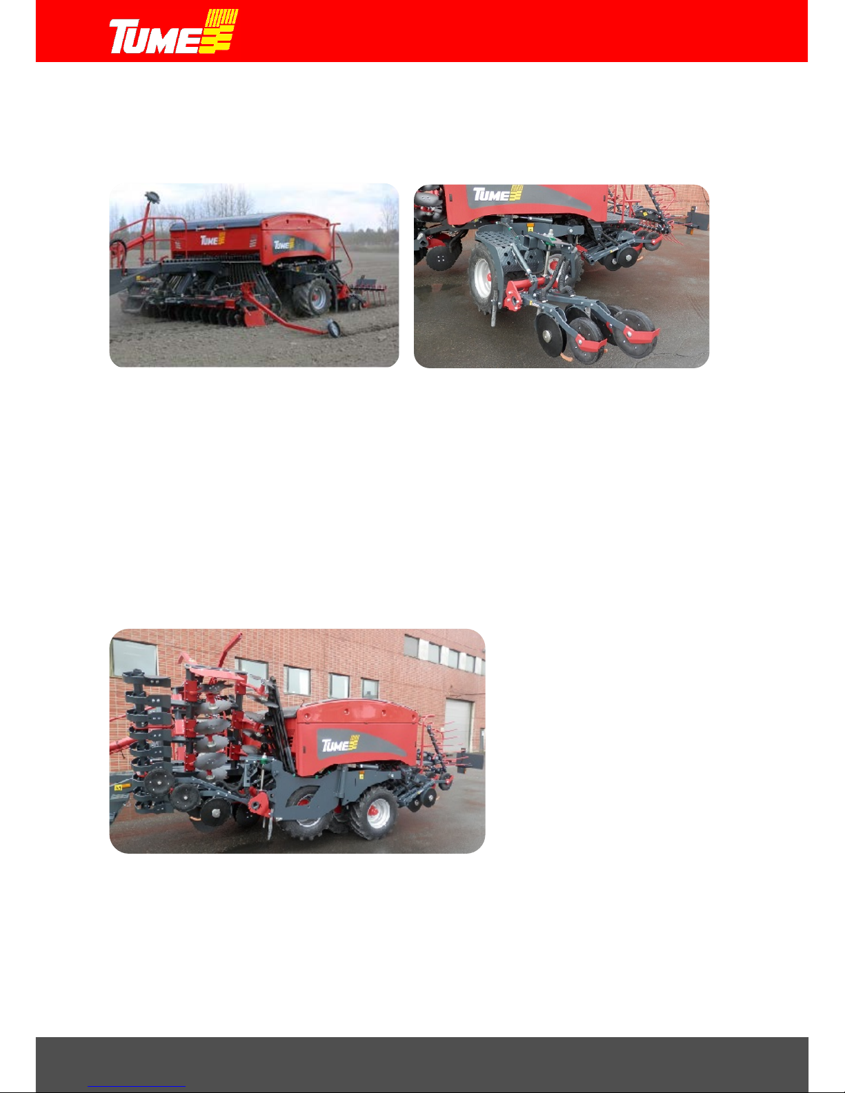
Picture 1. Draco 4000 in seeding position Picture 2. Draco 4000 Folding stage
Picture 3. Draco 4000 in the road transport positio n Picture 4. (Reserve)
Page 9

Draco 3000 / Draco 4000
9
3. MACHINE APPLICATION
TUME Draco seed and fertilizer drill is suitable for seedin g the seeds o f the m ost com mon cereal, oil
and grass plants, as well as for peas and beans . Grainy fertilizer can be so w n at the same time. The
fertilizer is mulched into the soil evenly using the front cultivator. If required, the machine can be
used separately only for fertilizing or only for seeding.
The required seed and fertilizer can be transported to the fields which are a short distance away
inside the machine's containers, if the roads are in good condition. In this case the maximum speed
allowed is 15 km/h. On uneven roads and long distances the transfers mu st be made w ith an empty
machine. The machine must not be used for other than transferring immediately needed seed and
fertilizer, and extra loads, objects, animals or passengers are not allowed to be carried in the containers or on the machine.
General about the use of the machine
There are two working widths of Tume Draco, 3 meters and 4 meters. The structure in the machines
is otherwise the same, but the 4 meter machine can be changed to 3 meters for transportation. This
happens by folding the front cultivator up, after which ½ meter sections are turned from the harrows
(both from right and left) to the front of the container, pictures 1, 2 and 3. The rear harrow also turns.
The folding function is explained in sections 11.2 and 11.3, EPEC seeding electronics. The 3 meter
model is fixed and it is not changed for transportation in any w ay. In this model the cultivator is made
of one part which moves in an up/down direction, same as the coulters and the rear harrow.
The fertilizer feeding device is designed only for feeding grainy fertilizers. There are usually
difficulties when feeding powdery fertilizers. At worst powdery fertilizers may cause feeding
equipment to cut and get stuck, which is why it is advisable to use only grainy fertilizers.
Fertilizer mixes evenly into the whole cultivation layer because of the cultivator in front of the
machine.
The seed coulters are equipped with two discs. The coulters penetrate well even in conditions which
include plenty of plant waste. The working depth is adjusted accurately with a roller wheel for each
coulter. The working depth adjustment is centralized so every coulter does not need adjusting
separately. The machine also has an automatic adjusting system, Autolevel, which keeps the
required seeding depth always correct. See section 11.6
The adjustment area of the coulter pressing is enough for all ty pes of soil. The adjusting is performed
hydraulically from the tractor. The coulter weight is 0 – 100 kg per coulter, and it is automatically
adjusted (see section 11.6).
The supporting wheels under the Draco's container level the fertilizer and pre-condense the soil for
the seeding coulters following behind. Pre-condensing ensure waters capillary rising so the seed can
reach it. The levelling / working depth adjusting wheel behind the coulter finishes the levelling.
The rear harrow spreads the soil between the coulters so the surface stays suitably grainy and does
not become muddy.
The machine has remote fertilizer adjusting device as standard. There are 3 memory spots which
can be electronically adjusted or changed even during the drive. There are no memory spots for
seeds, but even the seeding value can be adjusted from the drive computer.
More information on equipment can be found in section 13.
Page 10
Draco 3000 / Draco 4000
10
4. TAKING THE MACHINE IN TO USE
General
Tume Draco is delivered to the farm almost ready to use. The only installation required is attaching
the arms of the markers, which is explained in detail in section 13.1, Row Markers. Other required
actions are adjustments regarding seeding work.
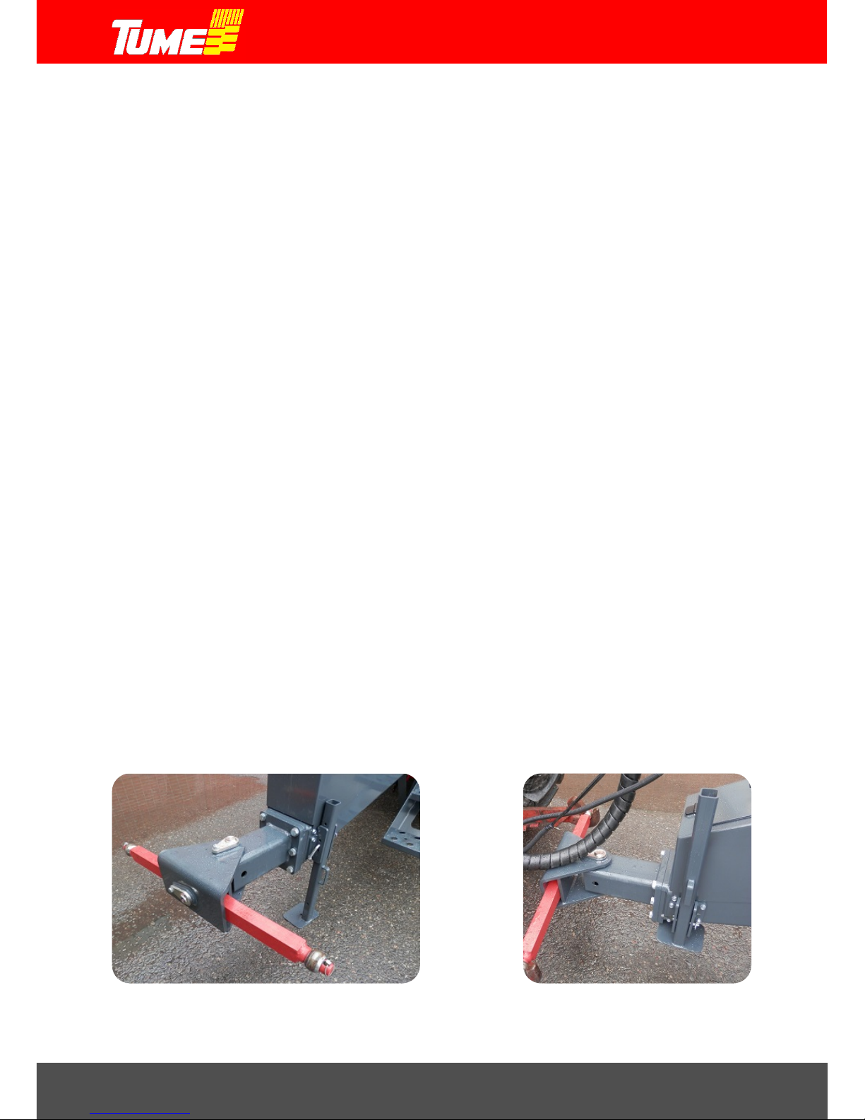
Support foot
There is a supporting foot in the front of the drive unit, picture 5. It is used when storing and
transporting as freight. When it is connected to the tractor, the supporting foot is lifted up, picture 6.
4.1 Connecting the machine to the tra c tor
S
tandard drawbar
Draco seed and fertilizer drill is connected to the drawbars of the tractor's 3-point lifting device (cat
3). Adjust the height of the drawbars so that the machine's container is in a horizontal position. This
is best checked from the seam of the top edge of the container's chain cover, because this is a line
covering the whole container. Make a note of the height of the drawbars and check at regular
intervals that the position is correct and the machine stays in the horizontal position.
WARNING!
Ensure sufficient weight for the front axle. When Draco is connected to the
tractor, make sure that at least 20% of the tractor's mass is on the front axle. If
necessary, use additional weights.
If the containers have seed and fertilizer in them during transfer, the driving
speed must not exceed 15 km/h. In transfer drive the brakes on the tractor's
right and left side must be connected together.
WARNING!
Check the wear and tear and other condition of all parts of the drawbar often!
Damaged or dangerously worn parts must be repaired or replaced immediately.
Page 11

Draco 3000 / Draco 4000
11
4.2 Connecting hydrauli cs
Tume Draco with standard equipment is connected to two double-phased hydraulics outputs in the
tractor. The hoses of the same color are connected to the same section. One of the valves works
the seeding (cultivator, coulters and row markers up/down) and the other changes the machine from
field use to road transport and vice versa. Select as the seeding valve the one that is the best and
most natural for the driver to use. Connect free return so that oil can flow freely to tractor. Hydraulic
front field drag (optional) requires a third double-phased hydraulic section.
Note! Familiarize yourself with section 11.6, Automatic working depth control, Autolevel
WARNING!
When connecting hydraulic hoses to the tractor, make sure that the machine,
drawbar or row markers cannot drop down uncontrollably and thus cause damage
to nearby people or other targets! Connect the machine to tractor's drawbars before
connecting hydraulics.
NOTE! In some tractor types you must use hydraulic quick connectors which differ from normal, but
are recommended by the tractor manufacturer. Exchange those parts when required to those
suitable for your tractor, in order to ensure the immaculate functioning of the hydraulics.
Connecting Epec seeding electronics is
explained in t heir entirety in sections 10 and 11, Epec
seeding electronics
4.3 Driving instructi ons
Driving instructions during transfer drive
The machine is in the top position supported by the tractor's hydraulic valve. For this reason one
must ensure that during transfer drive the tractor's hydraulics are not leaking and that the hydraulic
valve controlling the machine's rise and fall is not accidentally moved.
The maximum speed in transfer drive is 30km/h. See general safety instructions, section 2. It
contains many guidelines which must also be taken into account during transfer drive.
Driving instructions for seeding work
NOTE! Always move the machine forward the same time it is being lowered. In
other case the coulter rods may become damaged or coulters get blocked
.
Avoid unnecessary driving in the cultivated area. Choose a driving technique where you will leave
as few tyre marks as possible. It is usually best to start seeding around the field in such a way that
sufficiently wide headlands (usually the width of 1-2 times sprayer boo m width) are formed. After this
sowing is usually done by driving back and forth in the direction of the longest side of the field.
Page 12
Draco 3000 / Draco 4000
12
NOTE! Try to avoid sowing the corners of the field round so that the machine is
not lifted in corners. The machine's drive shaft and coulters will become
unnecessarily strained, if the machine is driven tight turns with coulters on the
ground.
Around the field sowing might be advisable on uneven fields. Lift the machine in the corner! Only
clearly obtuse corners can be sown whilst turning with the machine on the ground!
Make sure that the rear harrow lifts up when the machine is lifted. See section 12, Adjusting the rea r
harrow.
NOTE! Do not reverse when the rear harrow spikes touch the ground. Do not
reverse the rear harrow so that it gets stuck to the banks or other obstacles.
The machine must work on even ground in a horizontal position. See section 4, Connecting the
machine to the tractor
NOTE! Raise and lower the machine only when it is moving forward. Never
reverse the machine when coulters are on the ground.
Check from time to time that coulters are not blocked. Also check the condition of all seeding and
fertilising hoses and clean any blockages.
Check at the beginning of sowing for an area that can be sown with one container. After this you can
calculate the estimated next time of filling based on the readings in the area meter.
Keep enough seed and fertilizer in the container. Because of the shape of the bottom this should be
taken special notice of, especially at the start.
Do not keep fertilizer or seed in the containers for several days especially in damp weather. Damp
fertilizer may cause problems with feeding.
The best sowing result is usually achieved at a driving speed of 7-10km/h. In stony/rocky
circumstances the speed must be reduced to suit the situation. Maximum sowing speed with
small and normal seeds in good cond itions is 15km/h and with pea and bean so wing 6-7km/h.
Picture 5. Support foot down. Picture 6. Su pport f oot up, c onnect ed to t he tr actor.
Page 13

Draco 3000 / Draco 4000
13
5. USING THE FEEDING EQUIPMENT
General
In Tume Draco see d a nd f er tilizer drill both the seed and fertilizer feeding takes place using electric
motors. There are four motors: two on the seed side and two on the fertilizer side. Both right and left
side of the machine can be optionally turned off.
The seeding electronics EPEC in Tume Draco adjusts and monitors sowing quantities. The
machine's support wheels send impulses to EPEC, which can automatically take care of the correct
sowing quantity. The device continuously measures driving speed which correlates the rotating
speed of the electric motors so that the sowing quantity per hectare stays correct. More details about
this and calibration can be found in section 11, EPEC seeding electronics, section 11,5,13 and
11,5.16.
Block chains are not used much in power transmission. Only the chain cassettes which transmit
power from electric motors to feeding axles have block chains. The cassettes can be turned either
way up on both seed and fertilizer sides. When the cassette is installed in such a way that the smaller
chain wheel is on the electric motor axle, very small quantities of seed as well as fertilizer can be
sown, section 11.5.16, pictures 60 and 59.
6. FILLING THE CONTAINERS
Using tarpaulin covers
The seed and fertilizer drill is equipped with sel f-lowering tarpaulin cover. It can be opened from both
front and back edge. When filling the fertilizer container it is advisable to open the tarpaulin cover
only from the front and when filling the seed container, only from the back. Thus mixing fertilizers
and seeds at the filling stage is avoided.
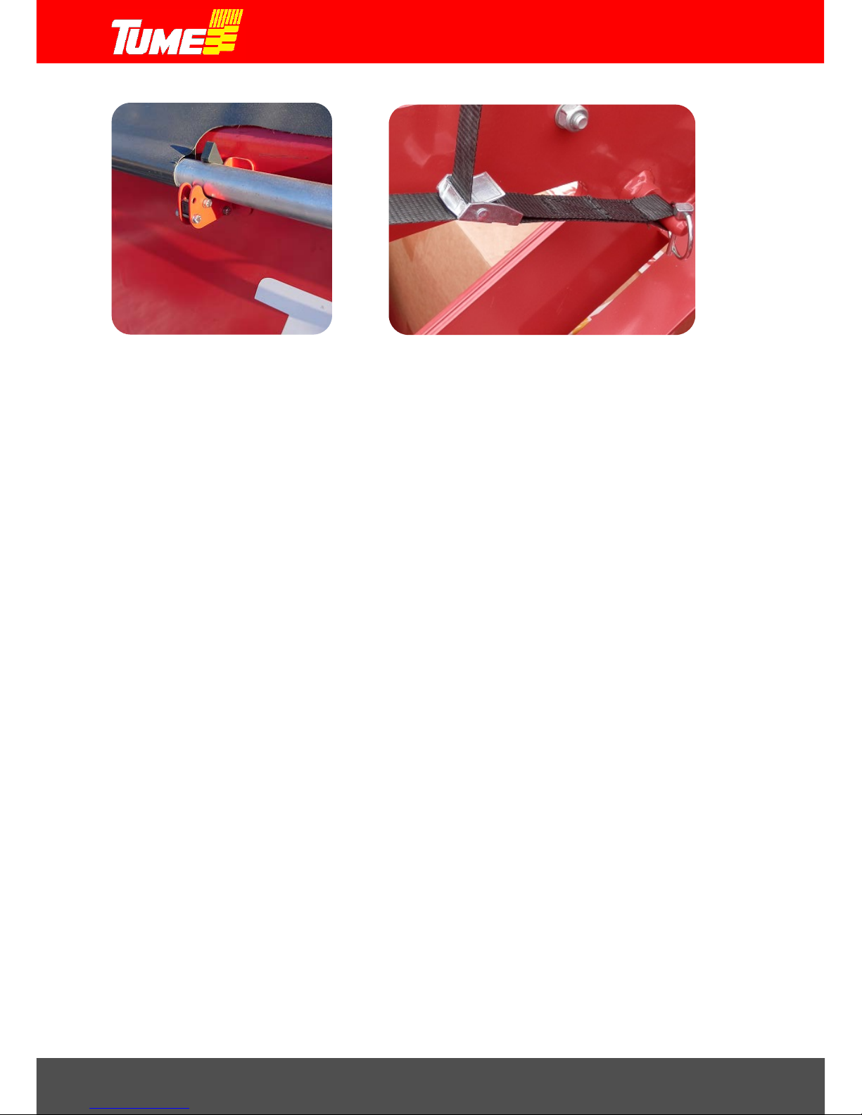
When the tarpaulin is closed, the tarpaulin hose locking devices must be locked, picture 7. The
container should always be kept carefully closed when it is not being filled.
The tarpaulin function is the same when opened from both front and back. When opening the
tarpaulin, it must be allowed to unroll slowly and the opening is controlled by holding the central
ribbon. When a suitable opening is reached (tarpaulin hose is next to the container's partition), the
central ribbon is tightened with the locking device, picture 8. Thus the opening is adjusted to the
suitable size for the next time the container is filled. If the container's partitions are adjusted, it is
usually advisable to also adjust the tarpaulin opening to match the partition. The remaining ribbon is
put inside the container on top of sieves. If, for some reason, sowing is done without sieves, make
sure that the ribbon cannot go into the feeding equipment!
Note! Before you start to fill containers, make sure that the container's draining holes are closed.
See section 7, draining containers and pictures 11 and 12.
Page 14
Draco 3000 / Draco 4000
14
Picture 7. Tarpaulin hose locking device Picture 8. Tarpaulin locking device
Using sieves
Draco seed and fertilizer drill usually has sieve equipment as standard in both fertilizer and seed
containers (there may be country-specific and mark et-specific exceptions). Sieves prevent foreign
objects, which risk disturbing feeding, such as clumps of fertilizer, getting into the feeding equipment.
The fertilizer sieve must always be kept in place during container filling and sowing. The seed sieve
must also be in place, apart from exceptional cases.
Exceptional cases are large-sized or long large seeds which are too big to fall through the sieve.
Many types of oats, for example, are problematic, because the grains are long and light. If there i s
a reason to suspect that the seeds may be too big to fall through a sieve, sieves should be
temporarily removed from the container. When filling and sowing without sieves, care must
be taken to ensure that foreign objects, such as pieces of bags, tools, etc. cannot get into the
feeding equipment.
Timing of the filling
When starting the sowing, it is recommended that the machine is transferred to the fie ld empty.
Fertilizers and seed are brought to the field on a trailer, for example, and the filling of the till seed
grill is done on the edge of the field. If the machine has to be filled far away from the field block to
be sown, the transfer drive with full container loads should be done with caution.
NOTE! The greatest trans fer speed of 30 km/h can be used on steady road s wit h empty
containers! The maximum speed with full containers is 15km / h! On bumpy, narrow or
stony roads the transfer drive speed mus t be adjusted e ven lower to sui t the c onditi ons.
Emptying of the containers can be monitored:
By looking into the container with camera or go out from time to time (the machine must be
stopped).
With EPEC sowing electronics. The machine will sound an alarm when the container has
only a small amount of fertilizer and/or seed l eft. The area meter can also be used to estimate
the next filling time.
Page 15
Draco 3000 / Draco 4000
15
WARNING!
Transporting an assisting person or another passenger on the steps or elsewhere on the
machine is absolutely forbidden. When seed or fertilizer is being levelled in the
containers, the seed and fertilizer drill must be parked!
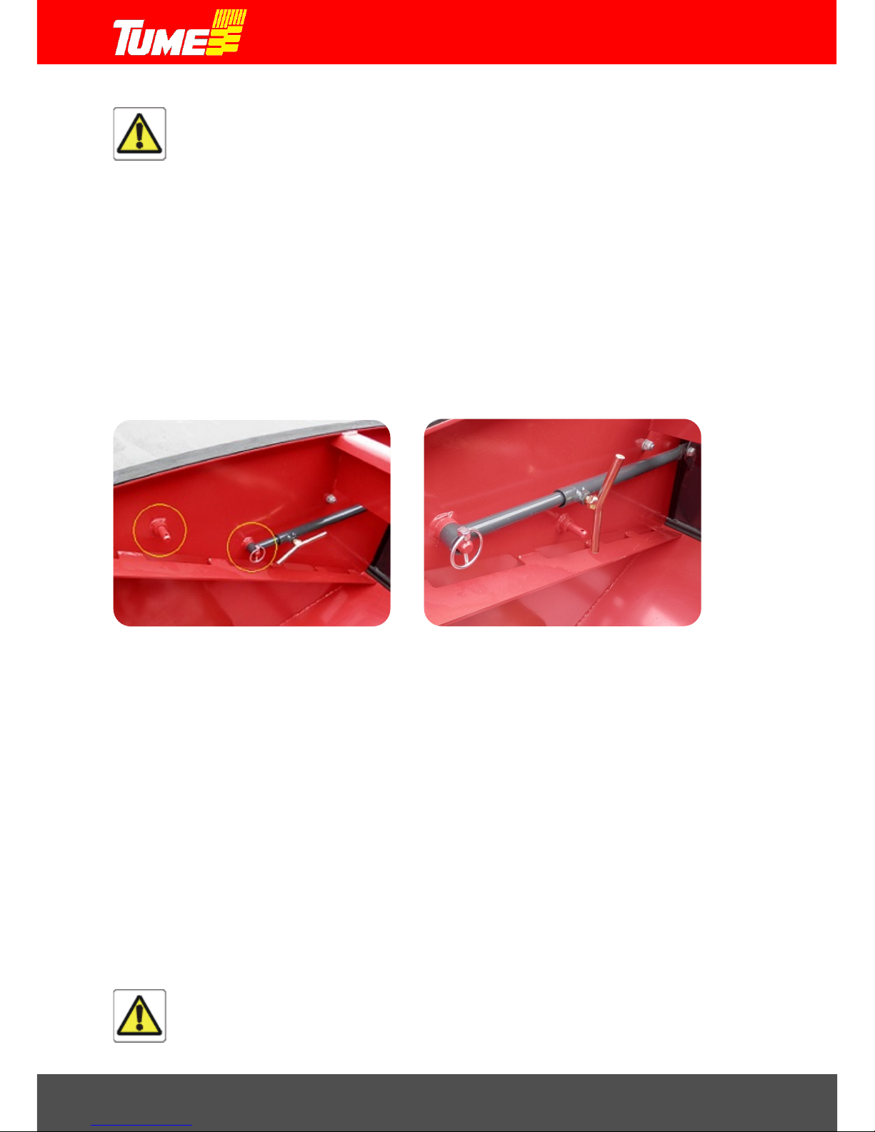
Adjusting the volume of fertilizer and seed containers
The position of the partition between fertilizer and seed containers can be adjusted so the containers'
volume ratios can be changed. Adjustment is done by opening the locking screws of wall support
rods, pictures 9 and 10 and by turning the partition to a desired position. Remember to lock the
support rods following the adjustment. The adjustment area of the partition can be changed by
moving the ends of the support rod into fastening pins, picture 10. W hen the machine is used for
sowing only, supporting rods should be in the fastening pins at the front.
NOTE ! Perform the adjustment when containers are empty or nearly empty!
Picture 9. Partition wall support ing rods in the Picture 10. Part ition wall supporting rods in the back-
front fastening pins fastening pins
The overall volume of the containers is the same in Draco 3000 and Draco 4000 machines.
-Overall volume is 4250 litres
-Seed minimum is 1780 litres
-Seed maximum is 2470 litres
-Fertilizer maximum is 2470 litres
Filling method
For filling small bags (such as 25-50kg, rape seeds etc.) we recommend a working method where
the bags are placed on a pallet which is lifted with a pallet crane o r front loader's forklift to a suitabl e
height regarding the machine's safe and easy filling. Jumbo bags (500-1000kg) can be handled with
different kinds of loaders. Jumbo bags must never be lowered on top of the seed and fertilizer drill
structures. Do not overload the seed and fertilizer drill. Find out about the methods to partially drain
a jumbo sack. We recommend that the whole jumbo bag can be emptied into the machine in one go.
WARNING!
When filling the machine, never go under a load hanging from a crane or a load
otherwise lifted up, or under the structures of the lifting equipment.
Page 16

Draco 3000 / Draco 4000
16
7. DRAINING CONTAINERS
Both the seed and fertilizer containers are emptied the same way
Tume Draco containers have four draining holes to ma ke d raining easier : Two i n the seed container
and two in the fertilizer container. The draining holes are close to the ends of the container and the
holes are opened and closed using sliding plates, pictures 11 and 12.
Note! Make sure that the draining holes are closed when you re-fill the machine.
Draining is best performed when protected from weather, under cover, for example.
Draining is performed one hole at a time.
It is easier to drain the Draco 4000 when the machine is folded into transport position. Then,
for example, the bag into which draining is made can be easily moved next to the machine.
Take the draining hose from its place (in the drive unit), picture 14.
Place the hose into your chosen draining hole. The hose has a control pin, which fits to the
grove in the draining hole flange. Rotate the hose ¼ turns, after which the hose stays in
place, picture 15.
Bring a bag next to the machine and place the end of the draining hose carefully inside the
bag.
Open the lock in the sliding plate and pull the plate open.
Let the material flow into the bag for as long as it comes under its own weight.
Go up and guide the material in the container towards the draining hole with a soft broom,
for example.
Drain the material through this hole for half the width of the container.
Brush the bottom of the container until as clean as possible.
Perform the above actions similarly from the other end of the container as well.
Finally empty the feeding equipment into calibration trough.
You can also take the option to vacuum the rest of the material with an industrial vacuum
cleaner.
Finally close the draining hole sliding plate and lock it by fastening with screws.
Take the bags away from the machine.
WARNING!
If you use compressed air to clean the containers, remember to use protectors which
prevent fertilizer dust, mordant etc. penetrating your breathing and eyes!
Picture 11. Draining sliding plate open. Picture 12. Draining sliding plate closed.
Page 17

Draco 3000 / Draco 4000
17
Picture 13. (Reserve)
Picture 14. Draining hose location Picture 15. Draining hose installed
Page 18
Draco 3000 / Draco 4000
18
8. ADJUSTING THE FERTILIZER DEPTH
Fertilizer is mixed into the soil using cultivator discs. Thus there are no separate fertilizer coulters.
Fertilizer is mixed with the whole cultivated layer. The cultivator's depth adjustment determines the
maximum depth into which the fertilizer goes.
It is more important to take note of the correct cultivating performance than where in the soil the
fertilizer goes. In any case the fertilizer will be for use by the plant. Most important is that cultivating
is done right with regard to conditions.
For example: in dry spring conditions it is advisable to avid cultivating too deeply. Then the water's
capillary rise to seed can be difficult and the germinating crop may suffer.
When you adjust the machine's fertilizer depth (and seeding depth, too) always make sure that the
machine is in a horizontal position (section 4: Connecting the machine to the tractor) If it is not
horizontal it will at once make both the cultivating and sowing depth incorrect.
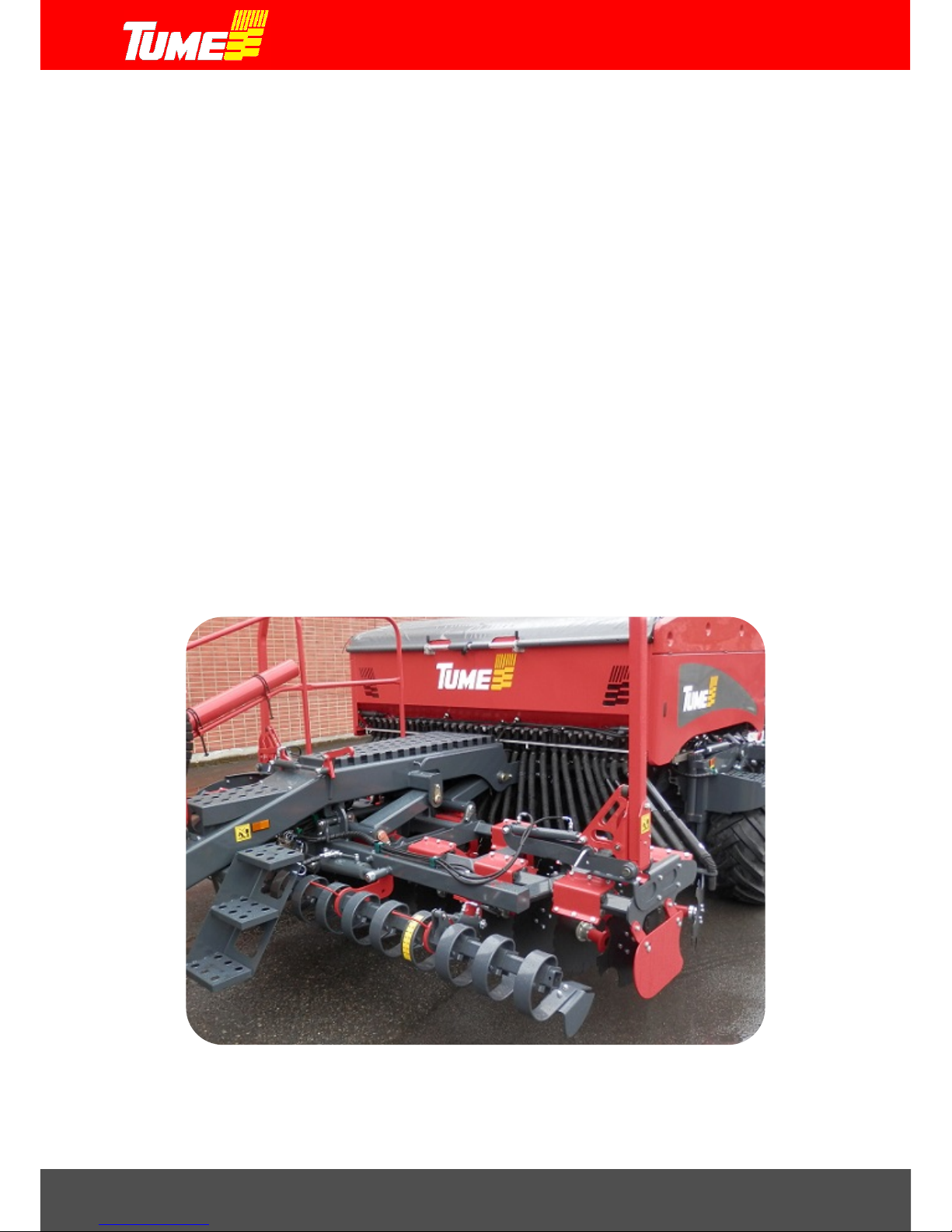
The cultivator's structure is shown in picture 16. The cultivator consists of cogged discs in tw o row s.
The shape of the discs and their position & geometry towards the soil is such that the cultivated area
will be as level as possible even with low cultivating depths.
The cultivator's penetrating the working depth and lifting in the headlands, as well as during road
transportation is connected to the same hydraulic valve as raising and lowering coulters: only one
hydraulic valve is in use.
Picture 16. Cultivator's structure
Page 19

Draco 3000 / Draco 4000
19
Adjusting the cultivator's working depth
The cultivator's working depth is adjusted by restricting the stroke of the cylinder which controls the
cultivator's height. This is done by adding or removing aluminum adjusting pieces around the cylinder
rod, pictures 17 and 18.
The cultivating depth can be adjusted from the field surface to the maximum depth of 9cm. There is
a total of 13 adjusting pieces. This means that one adjusting piece is less that one centimeter in the
working depth. If all adjusting pieces are on the cylinder rod, they have the minimum working depth.
Similarly, if all adjusting pieces are removed, the cultivating is done to the maximum depth. Additional
adjusting pieces can be kept attached to the drive unit rail, for example, picture 19.
Picture 17. Cultivator's working depth adjustment Picture 18. Cultivator's working depth adjustment
Picture 19. Adjusting pieces’ location Picture 20. (Reserve)
Page 20

Draco 3000 / Draco 4000
20
9. ADJUSTING THE SOWING DEPTH FOR THE SEED
Seed coulters are located behind support wheels. Each coulter has its own adjusting wheel for
working depth, but the working depth is adjusted in sections so there is no need to separately adjust
every wheel. Draco 3000 machine has 2 adjustable axles and Draco 4000 machine has them also
in the turning side sections, i.e. a total of 4 axles.
The structure of the seed coulters is shown in picture 21. Coulters are attached to a square pipe and
its angle is rotated with a cylinder. Separate limiting axles (pictures 23 and 24 part 1) and the
adjusting pieces on their necks determine the sowing depth.
Picture 21. Sowing coulters Pictur e 22. So wi ng coulter s
Sowing depth can be adjusted from the field surface to six centimeters. When all 12 ad justing pieces
are on the axle neck, the sowing depth is at its minimum. When all adjusting pieces are away, the
sowing depth is at its maximum. Additional pieces can be stored attached to the pipe in the bac k rail,
for example, picture 19.
Tume Draco has Autolevel sowing depth monitoring system. It monitors and adjusts sowing depth
when required: section 11.6, Automatic monitoring of the sowing depth.
Lastly we have the rear harrow as standard equipment, which finishes the structure of the field
surface so that risk of silting is reduced. More about this in section 12, Adjusting the rear harrow.
Picture 23. Limiting axle, centre section Picture 24. Limiting axle, side section Draco 4000
Page 21

Draco 3000 / Draco 4000
21
10. EPEC -SOWING ELECTRONICS, GENERAL
Sowing with Tume-Draco is controlled, monitored and adjusted using Epec controller as well as
tractor's hydraulics. The device controls all functions: the changing of the machine's sowing /
transport position (Draco 4000) as well as performing calibrations for both seeds and fertilizers.
Epec has five menus
- Start menu (appears, when device power is switched on), picture 25
- Folding menu, picture 26
- Settings menu, including service window, picture 27
- Sowing menu, picture 28
Picture 25. Start menu. Picture 26. Folding menu.
Picture 27. Settings menu and service window where you can see functioning of the valves and sensors.
Picture 28. Sowing menu.
Page 22

Draco 3000 / Draco 4000
22
10.1 Taking t he Epe c system to use
The contents of the instruction manual do not cover system installation. Epec is always part of the
standard equipment.
Correct settings (such as working width and progress) have been set in the factory and they can be
checked and changed. Other settings need to be made at the farm, such a s the values of the tramline
density and sowing quantities. The timings of the alarms as well as the brightness of the screen are
also adjustable.
10.2 Connecti ng power to Epec
Power supply is provided with a power cable which leads off the back of the screen. The cable has
a 3-pin plug in accordance with DIN norm. The tractor must have a corresponding socket which
complies with the norm for its dimensioning and connection. The power supply coming to the tractor
socket must be strong enough to allow continuous 25 A power, when the voltage, whilst the tractor
is running, must stay at the minimum level of 12 V, even when loaded, but at the maximum level of
14 V. The socket's power supply must have a fuse, maximum 30 A.
Epec system will store the programs, setting values and measuring results even when power is
switched off. Power supply can thus be cut off by unplugging the plug when the machine is not in
use. When the device is taken into use after the power cut, the feeding adjustments and the groove
stage of the drive groove device should be checked. When the machine is parked for a longer time,
voltage should be switched off (such as for the night).
Picture 29. 3-pin power supply plug
Picture 30. Data transfer cable connected. Picture 31. Data transfer cable opened
The information between the tractor's monitor and the seed drill is transferred with the data transfer
cable. The cable has an intermittent connector which can be opened (pictures 30 and 31). When
the tractor and the seed drill are removed from each other, this connector is opened. The monitor
stays in the tractor cabin. NOTE: store the ends of opened connectors so that water cannot enter
them. When the tractor is attached back to the seed drill, the cable must be re-connected.
Page 23
Draco 3000 / Draco 4000
23
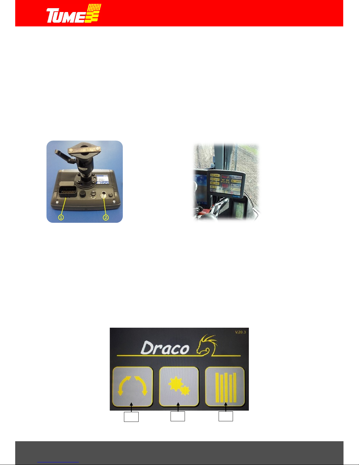
10.3 Epec moni tor location in the cabin
Ask your tractor's seller for a recommendation for attaching the monitor. Usually all tractor models
have a place for a monitor on the driver's right side or on the front right.
Note! Do not drill holes into the tractor cabin structures yourself: you might damage the tractor's
electric wiring or the heater's hoses.
The monitor must be attached firmly so that it cannot sway and vibrate. The device comes with a
backing plate and an attachment fixture which are useful when attaching the device. If you are
unsure, ask your tractor's repair shop for help.
Picture 32. Monitor's foot and attachment fixtures Picture 33. Monitor attached to the tractor.
1. Power and data plug.
2. Camera plug.
10.4 Starting the system
First check that the data transfer cable between the machine and the tractor is carefully connected
and secured. The connector and the plug can only be connected in one position, pressing them
lightly together. Connection is secured by turning the locking part about ¼ turns.
When the 3-pin plug is connected to the tractor, voltage is switched on. After a few seconds the start
menu is opened, picture 34.
Picture 34. Start menu.
1
2
3
Page 24

Draco 3000 / Draco 4000
24
11. EPEC -SOWING ELECTRONICS, USE
11.1 Start menu
When start menu, picture 34, has loaded, it has three options:
1. Folding menu
2. Settings menu
3. Sowing menu
Folding menu is used only in the 4 meter machine where it is changed to a 3 meter for road
transportation and vice versa. Folding menu cannot be activated for the 3 meter machine (factory
setting).
11.2 Changing the m a chine f rom sowing position to transport posi ti on
Folding menu is accessed from start menu by pressing button 1, picture 34. Folding the 4 meter
Draco from sowing position to road transport position happens in three stages. Turning takes place
using the machine's 2-phase hydraulic valve.
When folding is performed, the machine's coulters and front cultivator must be raised up. The folding
has thr ee stag es, pict ure 35. Moving from one stage to another takes place manually by pressing
the control unit. When the selected stage is activated, its button turns to red, pictures 36, 37 and 38.
Note! Folding into road transport position and sowing position must be strictly performed in
the order stipulated in this manual. If this is not adhered to, the machine's structures may be
damaged causing a great possibility of additional risks.
Picture 35. Folding menu
Stage 1: Turning the front cultivator up and folding the rear harrow up
Stage 2: Releasing the locking of the coulters' side sections
Stage 3: Turning the coulters' side sections to the front
Picture 36. Stage 1. Picture 37. Stage 2. Picture 38. Stage 3.
Page 25

Draco 3000 / Draco 4000
25
Folding requires the driver to see the realization of one stage to the end befo re the next stage
can be started. This is a safety factor. The driver follows the movements taking place when
the folding is not fully automatic.
Stage 1 is complete when cultivators are up and locking devices closed. Rear harrows have also
been lifted up. Fold front levelling board completely back, picture 39.
Stage 2 is complete when the side sections wheels rise up about 20 cm and the movement
ends. Side sections have been released from their locking, picture 40.
Stage 3 is complete, when side sections have folded 180 degrees to the front and their locks have
been fixed in place, picture 41.
Picture 39. Stage 1 complete . Picture 40. Stage 2 complete. Picture 40. Stage 3 complete.
Now the machine is ready for road transport. Start menu can be accessed from folding menu by
pressing the arrow on the bottom left, picture 35.
11.3 Changing the m a chine f rom transport position to sowing posi t ion
Folding menu is accessed from start menu by pressing button 1, picture 34. Folding the 4 meter
Draco from road transport position to sowing position happens in three stages. Turning takes place
using the machine's 2-phase hydraulic valve.
When folding is performed, the machine's coulters and front cultivator must be raised up. Unfolding
has thr ee stag es, pict ure 35. Moving from one stage to another takes place manually by pressing
the control unit. When the selected stage is activated, its button turns to red, pictures 36, 37 and 38.
Note! Unfolding from sowing position to road transport position must be strictly performed
in the order stipulated in this manual. If this is not adhered to, the machine's structures may
be damaged causing a great possibility of additional risks.
Note! Unfolding takes place in the reverse order to changing into transport position. This is
why unfolding starts at stage 3.
First stage 3: Side sections of coulters are turned from the front to working width, rear harrow unfolds.
Then stage 2: Locking the coulters' side sections to working width
Finally stage 1: Turning the front cultivator down to its working width
Page 26
Draco 3000 / Draco 4000
26
Unfolding requires the driver to see the realization of one stage to the end before the next
stage can be started. This is a safety factor. The driver follows the movements taking place
when the unfolding is not fully automatic.
Stage 3 is complete, when side blocks have folded next to the middle section and rear harrows have
unfolded to their working widths, picture 42.
Stage 2 is c om p lete when the wheels of the side section have come down to the same level as the
wheels in the middle section. Side sections are then locked into place, picture 43.
Stage 1 is complete when cultivators are down in their working width, picture 44.
Picture 42. Stage 3 complete. Picture 43. Stage 2 complete. Picture 44. Stage 1 complete.
Now the machine is ready for sowing. Start menu can be accessed from folding menu by pressing
the arrow on the bottom left, picture 35.
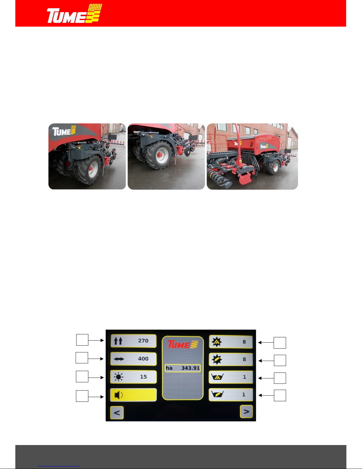
11.4 Settings menu and service window
Settings menu is accessed from start menu by pressing button 2, picture 34. Settings menu is used
to determine the machine's basic setting values. These are setting the progression (determines the
correctness of the sowing area), setting the working width, time delays of the axle guards and surface
monitor sensors, screen brightness and switching the alarm sound either on or off. The area
calculator (ha) in the centre of the settings menu is the total area that the machine has sown. It
cannot be reset. In the factory the machine was set with factory settings and it is not necessary to
change them. For this part the machine is ready for sowing work without changing the
aforementioned settings.
Picture 45. Settings menu.
1
2 3 4 5 6 7 8
Page 27

Draco 3000 / Draco 4000
27
Progression, button 1, picture 45
The value of progression shows how many centimetres the machine goes forward when the
supporting wheel rotates one turn. Experience tells us that with a 420/55-17 tyre the reading is 276
cm. However, cultivating the field and types of soil may affect progression by several percents. If you
need to change the reading, you press button 1 to activate the chan ge men u. You can increase the
reading with + button and reduce it with - button. Increasing the reading gives more hectares and
reducing the reading gives less hectares. The value is accepted by pressing OK button. The change
menu disappears at the same time.
Working width, button 2, picture 45
There is no need to change the working width, but it can be done using the same principle as the
progression.
Screen brightness, button 3, picture 45
Brightness can be adjusted to 15 different degrees. Press button 3 to activate the change menu.
When you press button + , brightness increases. When you press button - , brightness decreases.
When screen brightness is good, accept it by pressing OK button. The change menu disappears at
the same time.
Alarm sound, button 4, picture 45
Alarm sound can be switched either on or off. This happens when you press button 4. If the button
shows X as well as a loudspeaker image, the alarm sound is switched off. If you press the button
once, the X disappears and alarm sound is switched on.
Axle & Container monitoring, buttons 5, 6, 7 and 8, picture 45
Button 5: Monitoring the rotation of f ertilizer axle
Button 6: Monitoring the rotation of seed axle
Button 7: Monitoring the levels in the fertilizer container
Button 8: Monitoring the levels in the seed container
When you press any of the above mentioned buttons, a change menu for the function in question is
activated.
With a higher reading value the time delay of the alarm is longer than with a lower reading value.
Changes are made in the change menu with buttons + and - . The value is accepted with the button
OK, and the change menu disappears.
Note! If axle monitoring or container monitoring are set to the value 0 the monitoring is switched off.
This might be necessary in the following cases, for example:
-Extremely small amounts of seed are sown and the feed axle rotates so slowly that even value 1
raises alarm
-Seed container has a very small amount of small seeds and the container monitoring raises the
alarm for nothing
-Only seeds are sown so monitoring the empty fertilizer container needs to be switched off
Page 28

Draco 3000 / Draco 4000
28
Leave the settings menu and return to the start menu by pressing the arrow in the bottom left. By
pressing the arrow in the lower right corner, you get to the service window (picture 46).
Service window
Service window is opened by pressing the arrow symbol in the lower right corner in settings menu
(picture 45). The purpose of this screen is to give information about the operation of the machine.
Icons cannot be selected or change their state by pressing the screen.
Picture 46. Service window.
Hydraulic valve, sensor or tramline system is active when the color of the icon changes from grey to
blue or yellow. Lines indicates the location of the valves, sensors and tramline equipment. For
example in the picture above disc harrow sensor U /D2 is active. Solenoid valves and tramline system
are marked with blue icons. Sensors are marked with yellow icons.
11.5 Sowing m enu
Sowing menu is accessed from start menu by pressing button 3, picture 34. Sowing menu opens.
Sowing menu is used to control the whole sowing job. Epec sow ing electronics is used for performing
calibrations for both the seed and the fertilizer, for making tramlines for plant protection, for
controlling markers and for halving the machine if required (either right or left half). Epec raises the
alarm if an axle stops or seed or fertilizer is running out. There are 3 resettable area meters in the
sowing menu.
The screen buttons in picture 46 also act as icons for different functions. They show which status or
stage is happening in the function in question. The window in the middle shows the container status
(20) and seed and fertilizer axle rotations: left = L and right = R (21), as w ell as w hether the coul ters
are up or down (22). Five horizontal bars in the middle of the screen indicates operation of the
tramline system (picture 47, icon 4). While one bar is red, only the other side of the machine is
making tramlines. If two bars are red, both sides of the machine are making tramlines.
Page 29

Draco 3000 / Draco 4000
29
Picture 47. Sowing menu.
Functions of the sowing menu buttons, picture 47.
1.Area meter 1 13. Fertilizer memory spot 1
2. Area meter 2 14. Fertilizer memory spot 2
3. Area meter 3 15. Fertilizer memory spot 3
4. Tramline system settings and state 16. Amount of seed to be sown
5. return button to start menu 17. STOP: Saving sowing stage regardless of lifting
6. Acknowledging alarms 18. ½ lift
7. Ritsi marking 19. Markers lifting by pole
8. Halving, left half 20. Container guard icons
9. Halving, right half 21. Axle guard icons
10. Left row marker 22. Coulters up / down icon
11. Right row marker
12. Speed display / camera function button
1 2 3
4
5
6 7 8
9 1011
17
18
19
21
15
16
14
13
20
12
22
Page 30

Draco 3000 / Draco 4000
30
11.5.1 Area meter ha1
Picture 47, 1. The area menu in question is activated when it is yellow. The button shows how large
an area has been sown since the last reset. Resetting is done by pressing the said button for a few
seconds. Change menu is activated in the middle, picture 48. By pressing OK area is reset and the
change menu disappears. By pressing the button C, the area is not reset and we return from the
change menu to the sowing menu.
Picture 48. Area change menu.
11.5.2 Area meter ha2
Picture 47, 2, Similar to area meter ha1
11.5.3 Area meter ha3
Picture 47, 3, Similar to area meter ha1
11.5.4 Tramline functions
Picture 47, 4, The button icon shows the tramline stage (the first number) and tramline density
(second number). The tramline stage shows which driving stage is happening since the previous
tramline. tramline density shows at how many sowing intervals tramlines are formed.
The number of the tramline stage changes to the next one every time the coulters are raised up.
When the tramline stage reaches the same number as the tramline density, tramlines are formed
during next sowing.
The tramline stage, as well as the tramline density, can also be changed manually from the controls.
This happens when the button 4 is pressed for a few seconds. Tramline change menu is activated
in the middle, picture 49.
Page 31

Draco 3000 / Draco 4000
31
Picture 49. Tramline menu left picture. Red bars indicate which tramline equipment is in use.
Readings can be changed in the tramline menu using buttons + and - . When the button OK is
pressed, the set change takes place and the change menu disappears. By pressing the button C,
the tramlines stay the same, change does not happen and we return from the tramline menu to the
sowing menu.
Meter value in the screen tells the distance between the tramlines. This is the same as the width of
the sprayer used. In Draco 4000 the tramlines can be set by steps of two meters. To do these
asymmetric tramlines both markers must be activated from the monitor (picture 47, icons 10 and 11).
In situations where only other half of the machine makes tramlines the machine cannot otherwise
know which side of the machine should do the tramlines. For example when making tramlines to the
right side of the machine the left side is feeding normally. When turning in the headland and coming
back, right side is making tramlines again. Now tramlines are made so that the seeding seam is in
the middle of the tramlines. Bars in the middle of the screen indicates which side’s tramlines are in
use. For example, in the picture above both sides are making tramlines.
When the button 17, STOP, picture 46 is pressed, the button color chan ges to red. Then the machine
can be raised and lowered in such a way that the tramlines does not change. This function is good
when sowing around the field, for example, when the selected tramline has to stay the same for the
whole lap of the field. In t hat case the row mark er does not change, either. When STOP button is
pressed for the second time, the button's color changes to grey and the function returns to the mod e
where tramlines stages (and markers) function normally.
11.5.5 Return button to the start menu
Leave the sowings menu and return to the start menu by pressing the arrow in the bottom left (button
5, picture 47).
11.5.6 Acknowledging alarms
When button 6, picture 47, is pressed the alarm sound is acknowledged an d disappears. Alarm takes
place when seed or fertilizer in the container gets lower than the alarm limit, for example. When the
machine raises the alarm, the button's color changes to red.
Page 32

Draco 3000 / Draco 4000
32
11.5.7 Ritsi marking
Ritsi marking means that the tramline locations are also marked mechanically to the field. This
function is needed when sowing plants which need spraying before the plant has reached the
surface. Actual tramlines are not yet visible then.
With Tume Draco this is done using row markers: during the sowi ng next to the tramline (the tramline
number is then 1) both of the machine's row markers are lowered down. Then the othe r row marker
draws a line to the centre of the previous tramline stage. So the mark works as a centre mark during
spraying.
Ritsi marking is switched on by pressing button 7, picture 47. The button's colour changes to yellow.
Similarly, when the button is pressed again, the colour returns to grey and Ritsi marking is switched
off.
Note! Be extra cautious when in Ritsi marking mode, because both row markers are lowered down
at the tramline stage 1. This may cause a risk to the environment, for example when filling the
containers.
11.5.8 Halving, left, L
11.5.9 Halving, right, R
The machine's working width can be halved. The feed axles of both the right and left side can be
halved. When the button is pressed, it changes to red and at the same time the axle guard images
for fertilizer and seed stops rotating. Halving function goes automatically off when coulters are lifted.
The halving can be switched on and off freely either when sowing or when coulters are raised up.
11.5.10 Row marker, left, L
11.5.11 Row marker, right, R
Row markers are controlled with buttons 10 and 11, picture 47. The activated button's colour is
yellow. If both buttons are activated (yellow), the row markers automatically change from one side
to another when the machine is raised and lowered. Row markers are connected hydraulically to the
coulters' lifting and lowering hydraulics, so they are raised the same time as coulters, when reaching
the headland, for example. The exception of this is the pole lifting function (section 11.5.19), if there
are obstacles on the field and only the row marker needs to be raised up.
Examples of use:
You don't want to use row markers. Press row markers buttons 10 and 11 s o that they are both grey.
When coulters are raised and lowered, row markers stay up.
Only left row marker is in use. Only the left button is yellow. When coulters are raised and lowered,
the left row marker raises and lowers at the same pace.
Page 33

Draco 3000 / Draco 4000
33
Only left row marker is in use. Only the right button is yellow. When coulters are raised and lowered,
the right row marker raises and lowers at the same pace.
Row markers automatically change from one side to the other. When coulters are raised, the row
markers are first switched off by pressing the buttons until their colour is grey. The row markers are
activated into use (the colour of the buttons changes to yellow) so that the first r ow marker t o be
activated is the one which should come down first. Then row markers will take turns when coming
down.
You want to raise coulters up in the middle of sowing, but do not want the tramline stage or the row
marker to chang e. Press STOP button (picture 47, 17) before raising coulters. Its colour changes to
red. After this coulters can be raised and lowered, to avoid a rock or another obstacle without the
tramline stage stepping or the row marker changing sides. Remember to cancel the STOP function
by pressing it again when the obstacle has been passed.
Lifting only a row marker without interrupting sowing. Press button 19 until its colour changes to red.
Pole lifting prevents raising the coulters, so that when the tractor hydraulics raises/lowers the seed
drill, only the row marker raises/lowers. This function is used when sowing should not be interrupted,
but the row marker must be raised up because of an obstacle. Note! Remember to switch the
pole lift off at once (by pressing button 19 again, the colour changes to grey) after passing
the obstacle. Otherwise at headland coulters are not raised up and then, when reversing for
example, you will cause COULTER DAMAGE!
Starting sowing in the middle of the block so that both row markers should be lowered during the
first drive. See section 11.5.7, Ritsi marking. Drive the start in question with the tramline stage 1 s o
that Ritsi marker is switched on.
When you are going to public roads or when you go to fill containers. Switch the row markers off by
pressing buttons 10 and 11 so that their colour changes to grey. The rods won't then come down
when the coulters are lowered.
11.5.12 Speed display / camera function
While machine is not moving and coulters are up, Tume logo will appear to the place of the speed
display. It shows the driving speed while seeding. It is measured from the large wheels under the
hopper.
Note! The speed shown in monitor may differ from the speed your tractor shows. This can be
resulted from several reasons such as wheel slipping and tractor computer settings. Little difference
between speeds won’t need any actions.
Tume Draco is equipped with two cameras. One camera is in the hopper. You can monitor the
draining of the hopper. This is useful especially with seeds you don’t use much for hectare and the
hopper is quite empty all the time. One camera is located at the back of the machine so that it can
monitor the sowing and the function of the rear harrow. If, for some reason, a coulter is blocked, it
will show clearly on the camera.
Page 34

Draco 3000 / Draco 4000
34
When the camera is switched on (button 12, picture 47), the sowing menu screen changes to the
one shown in picture 50. The logos in the buttons and functions become smaller so that the image
shown on the camera is as large as possible on the screen.
All functions can be used, but adjustable / set values cannot be changed when came ra is in use : the
buttons on the bottom of the screen (picture 47, buttons 5-11 and 17-19) function in the same way
as in the sowing menu without the camera.
Instead, the setting values of buttons 1 – 4 and 13 – 16 (vertical in the edges) cannot be changed:
areas cannot be reset, changes to tramline stage cannot be made manually, the sowing quantities
of fertilizer and seed cannot be changed in the memory spot, but fertilizer's memory spot can be
changed from one spot to another when changes in the soil type so require. If the values of the
aforementioned buttons should be changed, the camera mode must be removed by pressing the
screen on speed display section, picture 50, when we return to the basic sowing menu, picture 47:
all values can then be freely changed.
Picture 50. Sowing menu when camera function is in use.
(see picture 47, sowing menu without camera function)
On the top r ig ht c or ner in pi ct ure 5 0 th ere i s a cam er a ic on wit h a l et ter A. T his m ea ns th at c am era
A is selected and its picture is shown in the middle of the screen. By pressing this icon you can
switch between the cameras. If A+B is selected the picture will change automatically after few
seconds between cameras A and B.
11.5.13 Fertilizer feed amount, memory spot 1 and fertilizer calibration
11.5.14 Fertilizer feed amount, memory spot 2 and fertilizer calibration
11.5.15 Fertilizer feed amount, memory spot 3 and fertilizer calibration
Tume Draco has three quick picks, i.e. memory spots for the amount of fertilizer feed. They are all
equal: they can all be changed separately. Calibration can also be made optionally using any of
them.
The fertilizer feeding devices are equipped with spiral rollers below them there are adjustable bottom
flaps. There are two adjusting levers, at both ends of the machine, pictures 51 and 2.
Page 35

Draco 3000 / Draco 4000
35
All kinds of grainy fertilizers can be sown through the fertilizer container. It is advisable to avoid
powdery fertilizers. Adjust the bottom flaps into the slot 2 with both the ri ght and le ft adjusting levers.
The whole fertilizer feeding equipment is made from non-corrosive materials. It is important that the
bottom flaps are in the correct position and they are not adjusted after calibration w ithout performing
a new calibration. Bottom flaps will give way if a hard foreign object gets between the bottom flap
and the feeder roller.
NOTE! When the bottom flaps lever is opened past the scale, seed can flow freely out of the
container. This is done when the machine is drained (section 7).
Picture 51. Adjusting bottom flaps, Picture 52. 1. Adjusting bottom flaps, left-side fertilizer
right-side fertilizer. 2. Calibration trays lever in sowing position
Picture 53. Fertilizer feed electric motor Picture 54. Fertilizer feed transmission cassette
The feeding of both fertilizer and seed takes place with electric motors, picture 53. The fertilizer
power transmission has only one chain in use in both sides, picture 54. Always keep the power
transmission on grainy fertilizers as shown in picture 54. The bigger chain wheel of the cassette is
on the electric motor axle. Make sure that the cassette pins are carefully put back in place.
Page 36

Draco 3000 / Draco 4000
36
Before you fill the containers with fertilizer and seed, make sure that the bottom flaps are in the
correct slot and that all four draining holes of the containers are closed, picture 12.
The machine does not have a sowing table for fertilizer or seed. The required feeding amounts are
given to EPEC as readings which are measured with calibration and set into the EPEC memory as
correct.
Both calibrations are performed from the calibration test unit on the left end of the machine, picture
55. The operating switch for calibration is on top of the rotation unit. The switch is accessed by lifting
the protective cover in front of the unit upwards. When the switch is used forward, the electric motors
of the fertilizer feeder device are activated. Similarly by using the switch backwards, the electric
motors of the seed feeder device are activated.
Picture 55. Calibration test unit
The motors run only while the lever is kept manually switched on. When the lever is released, it
returns to its center position and electric motors stop immediately.
The calibration of both fertilizer and seed takes place in the same way. Small seeds, for example,
differ when adjusting the seed amount, and this is explained in more detail in section 11.5.16.
When calibration is started, the calibration tray lever picture 52, Lever 2, is turned upwards into
vertical position. Then calibration trays slide under the feeding chambers.
Calibration trays are located next to funnels, picture 56. Make sure that the calibration trays are
empty and dry by emptying them, picture 57.
Page 37

Draco 3000 / Draco 4000
37
Picture 56. Fertilizer calibration tray. Picture 57. Pulling the calibration tray out.
When fertilizer calibration trays have been emptied and dried, push them back in place.
Use the calibration operating switch forward for a few seconds. Fertilizer flows into the trays and the
fertilizer feeding devices fill up ready for the actual calibration.
Empty the fertilizer trays into the fertilizer container and put them back in place.
Select as active any of the three fertilizer feeding amount memory spots, b utton 13, 14 o r 15, pi cture
47, Sowing menu. Press the button in question for a few seconds and the adjusting menu for sowing
amounts opens, picture 58.
Picture 58, Sowing amounts adjusting menu
The button kg (icon 1.) on the top left has been activated to yellow. Calibration is most acc urate
when it is made with your most usual fertilizer amount, such as for 450 kg per hectare. Set the
amount of the calibration in kilos and accept by pressing OK button. The sowing amounts adjusting
menu disappears and we return to the sowing menu.
1
2
Page 38

Draco 3000 / Draco 4000
38
Next turn the switch of the rotation unit (picture 55) forward (icon: fertilizer grains) and keep it
switched on continually as long as electric motors rotate and feed fertilizer into calibration trays.
Weight the result and multiply it by 100.
Example: Target is to sow fertilizer 450 kg/ha and the weighted amount is 4,1 kg.
4,1 kg*100 = 410 kg. Set value 450 to the monitor.
Press again the button of the same memory spot (with which the calibration was just done) for a few
seconds. The sowing amounts adjusting menu opens. Press button “Cal kg” (icon 2.) and enter the
weighing result * 100 as the value. Accept by pressing OK and you will return to the sowing menu.
Define the setting by doing the calibration as many times as necessary, until you think that
the required fertilizer amount per hectare and the value of the weighing result are close
enough to each other.
After this you can freely set the feeding amounts of your fertilizer into the memory spots, buttons 13,
14 and 15, picture 47.
This is done by pressing the selected memory spot button for a few seconds: the sowing amounts
adjusting menu opens, picture 58.
The button kg on the top left has been activated to yellow. Use number keys for the fertilizer amount
which you wish to set to the said memory spot. When you have set the required amount, accept it
by pressing OK button. The sowing amounts adjusting menu disappears and w e return to the sowing
menu. The value you set above has been saved as the value for the said memory spot.
Set values for two more fertilizer feed amount memory spots in the same way.
You can change fertilizer amounts from one value to another, either changing the memory spot or
by changing the value of the memory spot as explained above.
Note! Finally remember to turn the calibration tray lever back into its sowing position, picture
52.
EPEC has, as a factory setting, the correct amount of calibration rotations, so that it corresponds to
one are area, both for fertilizer and for seed.
11.5.16 Seed feeding amount, calibration and settings
Tume Draco can be used for sowing all usual grains, beans, peas and small seeds.
The seed feeding devices are equipped with pin rollers below which there are adjustable bottom
flaps. There are two adjusting levers, at both rear corners of the machine, pictures 59 and 60.
Remember to adjust both sides!
Page 39

Draco 3000 / Draco 4000
39
The bottom flaps have four adjusting positions:
Slot 1 Small seeds
Slot 2 Usual seeds, grain
Slot 3 Large seeds, such as peas
Slot 4 Extra large seeds
It is important that the bottom flaps are in the correct position and they are not adjusted after
calibration without performing a new calibration. Bottom flaps will give way if a hard foreign object
gets between the bottom flap and the feeder roller.
NOTE! When the bottom flaps lever is opened past the scale, seed can flow freely
out of the container. This is done when the machine is drained (section 7).
Position 4 of the bottom flaps is used only when sowing extra large seeds (such as some canned
pea varieties). Note that the feeding amount can increase in position 4, if you drive up a steep hill.
Picture 59. Adjusting bottom flaps, right-side seed. Picture 60. Adjusting bottom flaps, left-side seed.
Picture 61. Seed feeding electric motor. Picture 62. Seed feed transmission cassette.
Page 40

Draco 3000 / Draco 4000
40
The seed sowing amount is shown in the icon of button 16, picture 47, sowing menu
Seed calibration, adjusting the amount and saving the sowing amount with grains is done the same
way as that of fertilizer (section 15.5, 15). Calibration setting has its own button:
Press button 16 for a few seconds and the adjusting menu for sowing amounts opens, picture 58.
The button kg on the top left has been activated to yellow. Calibration is most accurate when it is
made with your most usual seed amount, such as for 280 kg per hectare. Set the amount of the
calibration in kilos and accept by pressing OK button. The sowing amounts adjusting menu
disappears and we return to the sowing menu.
In the calibration rotation unit, picture 55, the operating switch is us ed into the di fferent direction than
in fertilizer calibration: backwards (icon ear of grain) and keep it switched on continually as long as
electric motors rotate and feed seeds into calibration trays.
Weigh the result. Press button 16 again f or a few seconds. The sowing amounts adjusting menu
opens. Press button “Cal” and enter the weighing result as the value. Accept by pressing OK and
you will return to the sowing menu.
Define the setting by doing the calibration as many times as necessary, until you think that
the required seed amount per hectare and the value of the weighing result are close enough
to each other. Otherwise everything is done the same way as with fertilizer.
Example: Target is to sow wheat 230 kg/ha. Press seed icon few seconds and select kg, insert
230 and press OK. Do the calibration test and weight seeds. Weighted value from
calibration tray is for example 2,1 kg. → 2,1 kg*100 = 210 kg. Put 210 to monitor Cal
kg section. Press OK.
Page 41

Draco 3000 / Draco 4000
41
Sowing other seeds than grain
While s e e di ng s m a ll seeds such as rape seed you should use filler plates in the seeding chambers
(picture 63). Respectively while seeding large seeds such as pea and broad bean, a different filler
plate should be used. Soybean has its own filler plate.
While seeding large seeds the transmission cassettes should be in the same position as they are
with grains (picture 62).
Picture 63. Filler plates: small seeds soy pea and broad bean
When sowing small seeds (sowing amounts less than 20 g/ha) you must note two additional settings.
Power transmission cassettes for the seed feeding must be turned the other way round, picture 64.
Then the cassette's smaller chain wheel is put on the axle of the electric motor. Rotation speeds of
seed axles slows down. While target seeding amount is less than 10 kg/ha, computer will do
the calibration ten times, for ten ares. This gives more accurate result. Now you must multiply the
weighted amount by 10 and insert it to the monitor. Decimals are available with values less than 10
kg/ha. For example you can insert 5,5 kg for target value or weighted value.
Example: Target is to sow rape 5,5 kg/ha. Press seed icon few seconds and select kg, insert 5,5
and press OK. Do the calibration test and weight seeds. Machine does the calibration
now for ten ares. Weighted value from calibration tray is for example 0,48 kg. → 0,48
kg * 10 = 4,8 kg. Set value 4,8 to monitor Cal kg. Press OK.
Small seed filler plates must be installed into the seed feed chambers, pictures 65, 66 and 67. T he
small seed filler plates can be installed in place without tools as shown in pictures. When you return
to grain sowing, for example, they must be removed. It is advisable to use a small screw driver when
removing the filler plates. Do not damage the plastic parts. Installing and removing the plates can be
done using very little force.
Page 42
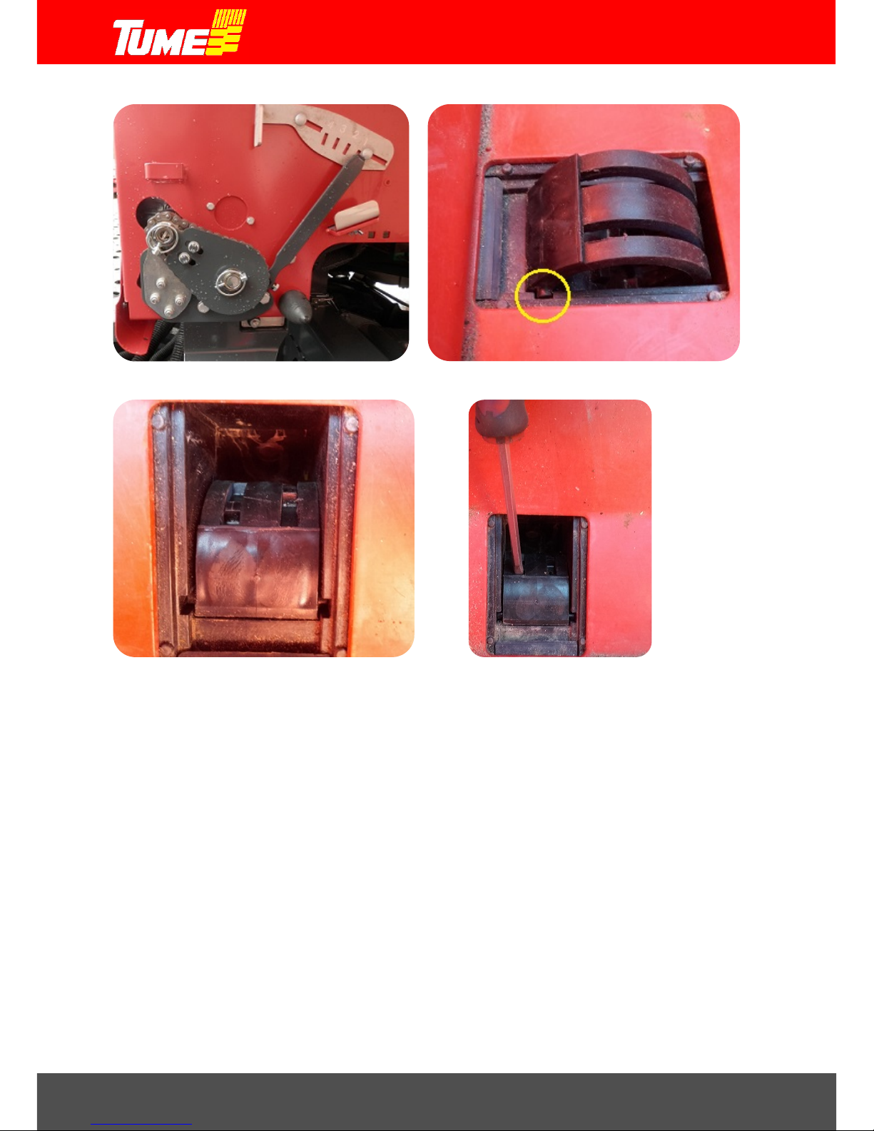
Draco 3000 / Draco 4000
42
Picture 64. Seed cassette on small seed setting. Picture 65. Installing a small filler plate.
Picture 66. Small seed filler plate in place in the chamber. Picture 67. Removing a small seed filer plat e.
Other filler plates are installed and removed same way as presented above.
11.5.17 STOP button
When you press STOP button (picture 47, 17) to activate it, its colour changes to red and the machine
can be raised and lowered without changing the sowing stage. Then the tramline device does not
step forward and the row marker does not change sides.
11.5.18 ½ lift
When you press ½ button (picture 47, 18) to activate it, its colour changes to yellow. Then the rear
harrow does not raise up when the machine is lifted. This feature is good in muddy conditions, for
example, when you wish the rear harrow to ground over the tyre marks when tu rning from headlands.
Note! Remember to switch the half lift off when you reverse or go to transport drive. Rear
harrow structures will get damaged, if the rear harrow is left down!
Page 43

Draco 3000 / Draco 4000
43
11.5.19 Pole lift of a row marker
When you press Pole lift button (picture 47, 19) to activate it, its colour changes to red and when the
machine is raised or lowered only the row mar ker raises or lowers. This function is used when sowing
should not be interrupted, but the row marker must be raised up because of an obstacle.
Note! Remember to switch the pole lift function off at once after you pass the obstacle!
Otherwise coulters will not raise up in the next headland and then, when reversing for example, you
cause SERIOUS COULTER DAMAGES.
11.5.20 Hopper monitor icons
Picture 47, icon 20: In the middle of the monitor you can see hopper level indicators. Upper icon is
for fertilizer tank and lower for seed tank. When a container starts to run low, the sensor gives and
alarm and the said container's icon changes to red. At the same time you hear an alarm sound.
Alarm can be switched off by pressing the button 6 .If the hopper level i ndicator is turned o ff (this can
be done in the settings window) the icon is grey.
11.5.21 Axle monitor icons
Picture 47, icon 21: On the left you can see fertilizer and seed axle monitors for left side and on the
right for right side. If for some reason the axle stops, its colour changes to red and it stops rotating
at the same time you can also hear an alarm sound . Alarm can be switched off by pressing the but ton
6.
If you use either (right or left) halves, the icons also stop to rotate, but the alarm sound is off.
11.5.22 Coulters up / down icon
Picture 47, icon 22: When the machine is raised up, the icon raises up and its color changes to red. When the
machine is lowered down, the icon lowers down and its color changes to yellow.
Icon 22 also gives inf ormation about the status of the automatic wor k ing de pth c o n tr ol. Mor e a bo ut th is in the
section Autolevel 11.6
Page 44

Draco 3000 / Draco 4000
44
11.6 Automatic sowing depth control Autolevel
The seed coulters sowing depth is explained in section: 9. Adjusting the sowing depth for the seed.
Tume Draco has as standard automatic sowing depth monitoring and automatic adjusting to ensure
that sowing will take place into the determined depth.
After the machine is lowered when leaving the headland, the tractor's valve is moved to holding
position (center position). Follow EPEC controller's icons from time to time.
Seeding depth control is managed by hydraulic pressure. Autolevel function prevents sowing too
deep by releasing pressure from coulters automatically. Respectively, if the seeding depth is too low ,
coulters icon (picture 47, icon 22) in EPEC monitor raises a bit and its color changes to red. This
means that the driver should increase the coulter weight. Increasing the coulter weight is done by
holding coulter lift/lowering hydraulic valve in lowering position until coulters penetrate deeper into
the soil and the coulter icon’s color changes from red to yellow. After this, return the hydraulic valve
to the center position.
When you reach a headland, raise coulters up normally and leave the hydraulic valve in the
center/holding position.
When leaving the headland for sowing, the hydraulics are repeated as explained above.
Autolevel controls in real time the working depth ratio of the support wheel and the coulter. Coulters
have two monitoring units, picture 68.
Picture 68. Autolevel monitoring unit.
Page 45

Draco 3000 / Draco 4000
45
12. ADJUSTING THE REAR HARROW
Picture 69. Rear harrow
Rear harrow lowers down when coulters are lowered down.
Rear harrow treats the surface of the soil w ith its own wei ght and it cannot be w eighted hydraulically.
It is also possible to leave it up when sowing, if so required. When coulters are in the upper position,
half lift is switched on from EPEC controller (button 18, section 11.5.18). The button's color will
change to yellow. When the button is pressed again its color returns to grey and the rear harrow
works normally.
The working angle of rear harrow spikes is controlled with a pin, part 1, picture 69.
The angle is adjusted when rear harrow is in upper position.
NOTE! It is forbidden to reverse the machine when the rear harrow spikes are touching
the ground. Reversing when the rear harrow is too low down can cause damages to
the rear harrow. See section 11.5.18, Half lift
Page 46

Draco 3000 / Draco 4000
46
13. ACCESORIES
13.1 Row markers
Row markers draw a sowing line on the field surface. Draco row marker mar ks the central line. Many
tractors have a viewfinder which makes following the drive line easier.
Note! Tractor drivers are often inclined to sit leaning slightly towards the right side. Make sure that
you sit upright when following the sowing line.
Row markers are adjusted so that the marking line is drawn exactly to the distance of working width
from the center of the machine. Marking plates locations and angles can be adjusted with screws 1,
picture 70. When the required adjustment is found, tighten the screws carefully.
Picture 70. Row markers
Row marker speed is factory adjusted but because of different tractor hydraulics, it may have to be
readjusted. Adjustment is made by rotating the screw under the cover on drawbar (picture 71). First
loosen the nut and make the adjustment. After that lock adjustment with the nut. It is recommended
to do adjustment after the oil has reached its normal operating temperature. Marker speed should
be so fast that it won’t slow down your seeding work, but not too fast so that it causes unnecessary
stress to the structures.
Picture 71. Row marker speed adjustment.
Page 47

Draco 3000 / Draco 4000
47
13.2 Hydraulic front harrow
Hydraulic front harrow has its own adjusting and user instructions.
13.3 Roller controller
Machine functions can also be controlled with a specific roller controller (picture 72). You can move
between the icons by rotating the wheel. Pressing the wheel will apply the function. Selection is
indicated with blue frame. For example, STOP is activated in the pic ture 72. C ont roller can be in the
armrest for example. It is useful especially when selecting halving in headlands or pole-lifting. It also
makes possible to locate monitor itself further from driver. Controller is connected to the cable in the
monitor. It starts working when the wheel is pressed.
Picture 72. Roller controller.
Page 48

Draco 3000 / Draco 4000
48
14. SPECIFICATIONS
Type/Feature
DRACO 3000
DRACO 4000
Working width (m) 3 4
Container capacity (l)
- Total 4250 4250
- Seed, min 1780 1780
- Seed, max 2470 2470
- Fertilizer, max 2470 2470
Base machine weight (kg)
- Empty 4900 6300
- Full of wheat and fertilizer about 8500 about 9900
- Coulter pressure per coulter (kg) 20-100 20-100
Base machine dimensions (cm)
- Height to the container edge
222
222
- Width
300
300
- Overall length 790 790
Wheels
- Size
420/55-17
420/55-17
- Surface pattern
Tractor pattern
Tractor pattern
- Amount
6 8 - Pressure (bar)
1,5-2,0
1,5-2,0
- Work depth adjustment wheels 330x65 330x65
Hydraulics
- Pressure (bar) 170 170
- Connection with standard equ ipment 1 x 2 phased 2 x 2 phased
- Seed coulters (units) 18 24
- Row gap (mm) 167 167
- Coulter pressure per coulter (kg)
Adjustment happens automatically
20-100 20-100
- Fertilizer is mixed into the cultivated layer
Noise level less than 70 dB (A) less than 70 dB (A)
Page 49

TUME-AGRI OY
PL 77
14201 TURENKI
FINLAND
TEL. 0207 433 060 TEL. (int .) +358 207 433 060
FA X 03 688 2305 FAX (int.) +358 3 6882305
www.tumeagri.fi
 Loading...