

Tulsa Rufnek 100, Rufnek 80 Service Manual

DESIGN SERIES 001
RUFNEK 100
AND
MODEL 80
SERVICE MANUAL
GENERAL INFORMATION ..........................................................................................................................4
INTRODUCTION AND THEORY OF OPERATION ................................................................................................................. 4
ASSEMBLY NUMBER EXPLANATION................................................................................................................................... 4
WINCH BREAK-IN .................................................................................................................................................................. 4
MODEL CODES ...........................................................................................................................................5
MAINTENANCE............................................................................................................................................6
OIL LEVELS............................................................................................................................................................................ 7
BRAKE IDENTIFICATION AND ADJUSTMENT...................................................................................................................... 8
DISASSEMBLY .......................................................................................................................................... 10
DRUM BRAKE DISASSEMBLY............................................................................................................................................. 10
ADJUSTABLE OIL BRAKE DISASSEMBLY.......................................................................................................................... 11
NON-ADJUSTABLE BRAKE DISASSEMBLY ....................................................................................................................... 12
RUFNEK BRAKE DISASSEMBLY......................................................................................................................................... 13
CLUTCH AND DRUM DISASSEMBLY.................................................................................................................................. 14
GEARBOX DISASSEMBLY................................................................................................................................................... 15
GEAR INSPECTION INSTRUCTIONS.................................................................................................................................. 16
ASSEMBLY ................................................................................................................................................ 17
GEARBOX ASSEMBLY ........................................................................................................................................................ 17
DRUM BRAKE ASSEMBLY .................................................................................................................................................. 18
ADJUSTABLE OIL BRAKE ASSEMBLY................................................................................................................................ 19
NON-ADJUSTABLE OIL BRAKE ASSEMBLY....................................................................................................................... 20
RUFNEK ADJUSTABLE OIL BRAKE ASSEMBLY ................................................................................................................ 21
CLUTCH AND DRUM ASSEMBLY........................................................................................................................................ 22
TROUBLESHOOTING................................................................................................................................23
BILL OF MATERIAL...................................................................................................................................24
ADJUSTABLE BRAKE BILL OF MATERIAL ...........................................................................................27
NON ADJUSTABLE BRAKE BILL OF MATERIAL ..................................................................................27
RUFNEK BRAKE BILL OF MATERIAL.....................................................................................................28
TORQUE SPECIFICATIONS CHART ........................................................................................................ 29
CLUTCH INSPECTION ..............................................................................................................................30
ISOMETRIC VIEW ......................................................................................................................................31
ADJUSTABLE BRAKE, HYDRAULIC MOTOR, & CLUTCH POSITION INDICATOR VIEWS................ 32
SEL-0049-001.DOC
REV-0 JAN 2006

FAILURE TO HEED THE FOLLOWING WARNINGS
MAY RESULT IN SERIOUS INJURY OR DEATH.
The safety of the winch operator and ground personnel should always be of great
concern, and all necessary precautions to insure their safety must be taken. The
primary mover and the winch must be operated with care and concern for the
equipment and the environment. Additionally, a thorough knowledge of the equipment
and its performance capabilities must be understood. These general safety guidelines
are offered, however local rules and regulations or national standards may also apply.
Recommended references are, but not limited to, ANSI B30, OSHA 1910, AWS D 14.3,
and SAE J706.
Additional information can be found at http://www.team-twg.com/TulsaWinch/
Indicates an imminently hazardous situation
which, if not avoided, will result in death or serious
injury.
Indicates a potentially hazardous situation which,
if not avoided, could result in death or serious
injury.
Indicates a potentially hazardous situation which,
if not avoided, may result in minor or moderate
injury or property damage.
Indicates information or a company policy that
relates directly or indirectly to the safety of
personnel or protection of property.
Mounting:
Winch mounting must be secure and able to withstand the applied loads.
• The stability of the mounting system must be approved by a qualified person.
• All welding should also be done by a qualified person.
• Winch mount must be flat so as not to induce binding.
• The flatness must not exceed 1/16 inch across the mounting surface of the winch
itself.
Guards must be placed on all open drives in the case of mechanical winches.
Insure that all hydraulic hoses, valves and fittings are rated to winch manufacturer’s
operating pressures.
Relief valves should be set to winch manufacturer’s specifications.
Insure that all PTO’s and drivelines are sized appropriately for the winch manufactures
speed and torque specifications.
2

Operator:
Must read and understand the operating and service manual.
Both the SERVICE MANUAL and OPERATING AND MAINTENANCE MANUAL
are available online at http://www.team-twg.com/TulsaWinch/
Must never lift or move people with this winch.
This winch is not designed or intended for any use that involves moving people.
Must stay clear of the load at all times.
Ground personnel should remain a safe distance from the load and winch cable
at least 1 ½ times the length of cable measured from the winch to the load.
Must stay clear of the cable at all times.
A broken cable can cause serious injury or death.
Must avoid shock loads.
Shock loads can impose a strain on the winch that can be many times the design
rating.
Must be aware of the fleet angle of the winch.
All loads should only be pulled with the load line perpendicular to the drum shaft,
this is to avoid excessive stresses on the winch and will help prevent the cable
from building on one side of the drum flange.
Must wear personnel protective equipment (PPE) if required.
Check the local, state and federal regulations for compliance.
Must insure that the drum clutch is fully engaged before hoisting.
A visual inspection of the drum clutch engagement is required before each
winching operation.
Must rig all loads secure before winching.
Pull the load line taut and inspect the condition of load for stability.
Must inspect the drum brake if equipped.
The drum brake is not a load holding device it is design to prevent over spooling
of the drum and causing bird nesting of the cable on the drum. Inspect the brake
for wear of the lining and the actuation method.
Must inspect the load control brake.
These winches can be equipped with two (2) forms of dynamic braking. The
worm brake is one method and is adjustable for pay-out load control. Before a
load is handled the load should be pulled tight and stopped to check this brake.
The second method is a hydraulic lowering control that is not field adjustable.
The same method should be used to check this brake.
Operation:
• All winch controls must be well marked for function to avoid confusion.
• Insure that the PTO is disengaged when the winch is not in use.
• All winch controls must be located to provide the operator with a clear view of the
load.
• The clutch must be inspected daily for proper operation.
• The winch cable should be inspected daily for serviceability.
• A minimum of five wraps of tightly wound cable must remain on the drum.
3

GENERAL INFORMATION
GENERAL INFORMATION
GENERAL INFORMATIONGENERAL INFORMATION
INTRODUCTION AND THEORY OF OPERATION
INTRODUCTION AND THEORY OF OPERATION
INTRODUCTION AND THEORY OF OPERATIONINTRODUCTION AND THEORY OF OPERATION
The Tulsa worm gear winch is operated by turning the input of the worm using a
hydraulic motor or PTO driven sprocket and chain. The winch utilizes the adjustable,
spring applied, multiple disc oil brake that activates only during pay-out to provide
maximum efficiency during pay-in. The torque is transferred from the gearbox through
the drum shaft which is keyed to a mechanically actuated sliding clutch that, when
engaged, transfers the torque to the drum.
ASSEMBLY NUMBER EXPLANATION
ASSEMBLY NUMBER EXPLANATION
ASSEMBLY NUMBER EXPLANATIONASSEMBLY NUMBER EXPLANATION
This manual is for design series 001. In the case of a major design change
implementation, a new design series designation number will be issued for the winch. A
new manual will also be created for that specific design series.
ASSEMBLY # SERIES
81370 001
DESIGN
WINCH BREAK
WINCH BREAK----IN
WINCH BREAKWINCH BREAK
Winches, like any other kind of machinery, require a “break-in” period to perform well
and to maximize their life. The following guidelines should be used in the break-in of
Tulsa Winches.
Use extreme care when first spooling cable onto the winch. DO NOT run the winch
at high speeds when performing this operation. Make sure that the cable is unrolled in a
line (to prevent kinks) and SLOWLY inhaul the winch to install the cable.
DO NOT exceed one half rated load or one half rated line speed for the first thirty
minutes of operation. This will insure that the worm and gear have an opportunity to
wear in properly. Periodically, check the gearbox for temperature rises and allow the
winch to cool down between pulls. Worm gear winches are designed and intended for
intermittent duty application only; using them in extremely long pulls may generate
excessive heat and shorten the life of the winch.
IN
ININ
4

RN100 W M R F O M X
Gear Type
W=Worm
P=Planetary
Drive Type
H=Hydraulic
M=Mechanical
Gearbox Position
L=Left
R=Right
(viewed from rear of truck)
Input Shaft Location
F=Front
R=Rear
X=Does not apply
(viewed from rear of truck)
Winch Type
M=Mechanical
H=Hydraulic
G=Speed Reducer
No. of Worm Starts
S=Single
D=Double
T=Triple
Worm Angle
L=Left
R=Right
Gearbox Location
L=Left
R=Right
(viewed from rear of truck)
MODEL CODES
MODEL CODES
MODEL CODESMODEL CODES
M80 S L R F O D CL
THE RUFNEK SERIES
WINCHES ARE ONLY
AVAILABLE WITH LEFT
HAND GEARS.
Motor Type
1. Single Speed Gear Motor
2. Two Speed Gear Motor
3. Single Speed Geroler Motor
4. Two Speed Geroler Motor
5. Piston
6. Vane
X. No Motor
Clutch Device
M=Mechanical
A=Air
Cable Spooling
O=Over Drum
U=Under Drum
(viewed from rear of truck)
Motor Type
CL-CharLynn
Motor Mount
D=Direct Mount
X=No Motor
Cable Spooling
O=Over Drum
U=Under Drum
(viewed from rear of truck)
Input Shaft Location
F=Front
R=Rear
X=Does not apply
(viewed from rear of truck)
5
MAINTENANCE
MAINTENANCE
MAINTENANCEMAINTENANCE
Tulsa Winch worm gear driven winches require regular maintenance to ensure safe
and reliable operation. Regular oil changes with the correct oil for the ambient
temperature conditions and an annual inspection of the wear components are strongly
recommended.
Maintenance Scheduling
The owner is to ensure proper inspection intervals, in compliance with the API RP
2D Section 4, ANSI B30.5, 5-2.3, or ANSI B30.7, 7-2.1, and will review winch usage
categories on a periodic basis. A qualified inspector should perform all maintenance
and inspections.
USE
(HRS PER
MONTH)
0-10 PRE-USE, ANNUAL
11-50 PRE-USE, QUARTERLY
51+ PRE-USE, MONTHLY
API RP 2D RECOMMENDED
INSPECTION SCHEDULE
Oil Maintenance
The oil in the gear section and the brake section should be changed every 1000 hrs or
6 months of normal usage. If your winch is mounted with a drum brake, do not fill the
brake with oil.
• Tulsa Winch recommends that the oil level in the gearbox be checked and
adjusted as part of the pre-use inspection. If the oil level drops frequently or oil
leakage is detected during an inspection, maintenance should be performed to
correct any problems.
GEARBOX OIL CAPACITY = 8 QTS
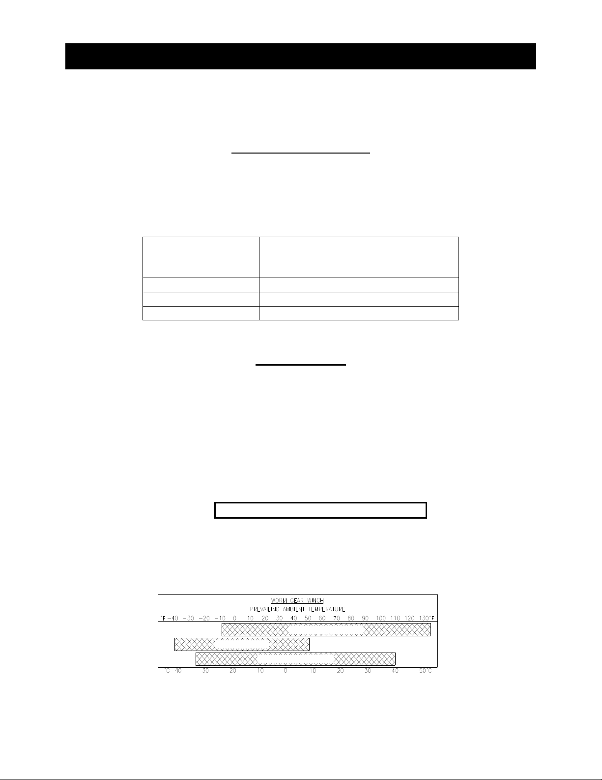
• Gearbox oil level inspection is achieved by removing the oil level inspection plug
and visually inspecting the oil level. Minimum oil level is to the bottom of the
threads of the inspection hole. Refer to the chart below for the recommended oil
type and grade for your application.
MOBIL SHC 626
MOBILUBE HD80W140
SAE 140W AGMA 7 EP
All oils must meet MIL-PRF2105E standards. Substitution from a reputable
manufacturer is allowed as long as type and grade are maintained.
6
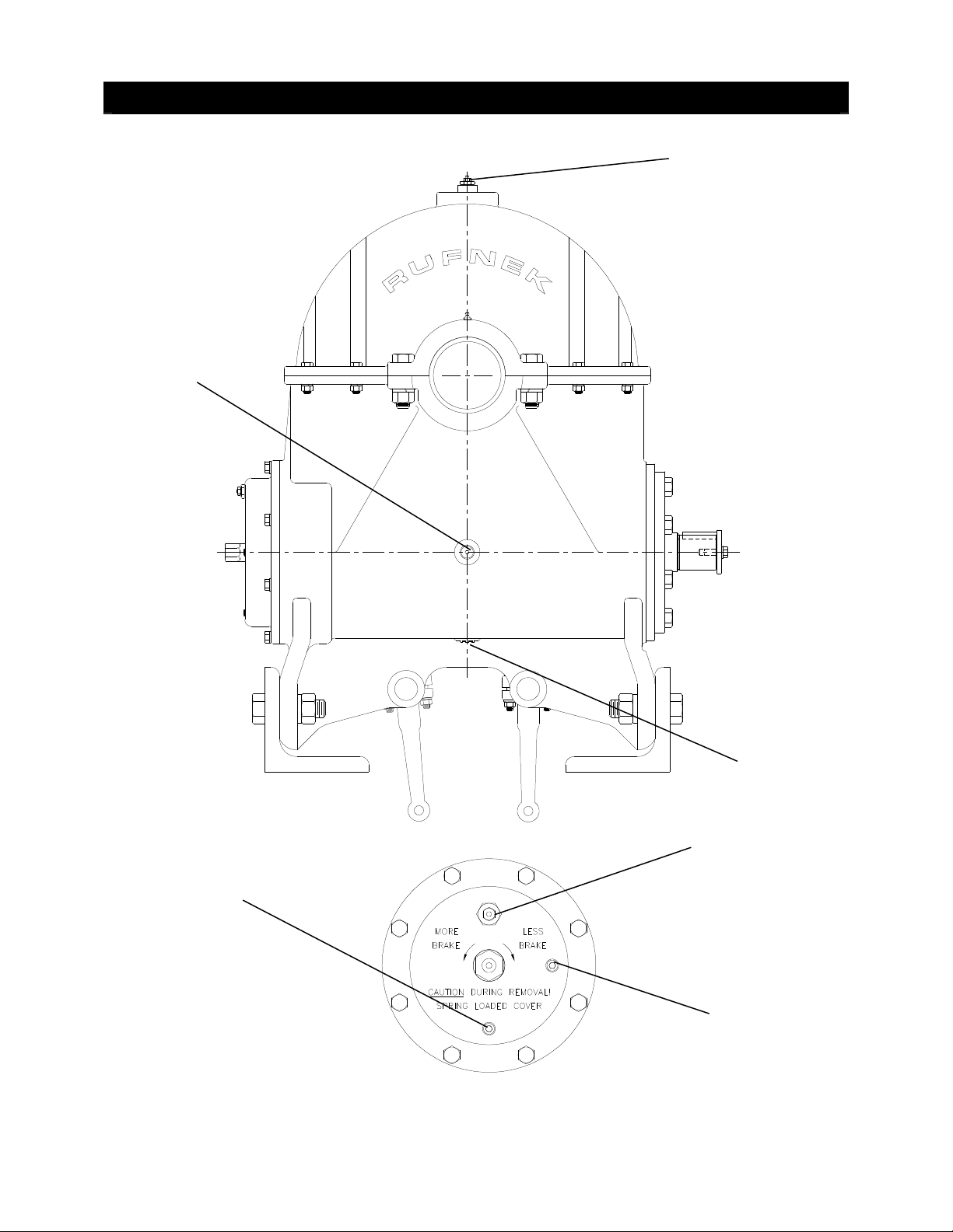
GEARBOX
OIL LEVEL
OIL LEVELS
OIL LEVELS
OIL LEVELSOIL LEVELS
GEARBOX
FILL/VENT
GEARBOX
OIL DRAIN
BRAKE
FILL/VENT
BRAKE
OIL DRAIN
BRAKE
OIL LEVEL
7

BR
BRAKE IDENTIFICATION
AKE IDENTIFICATION AND ADJUSTMENT
BRBR
AKE IDENTIFICATIONAKE IDENTIFICATION
In general, worm brakes on Tulsa winches should be set to hold the load you are
currently working with. Excessive brake torque will result in excessive heat generation
and brake wear. The best way to insure proper brake adjustment is to pull the cable
tight against the load and stop to ensure the brake holds. If it doesn’t, tighten the brake
slightly and try it again. If the brake doesn’t respond to adjustment the brake must be
serviced.
If the input to the winch is accessible and a torque wrench can be adapted to it, the
brake can be set with a torque wrench. The Model 80 brake is shipped from the factory
pre-set at 185 Ft.-Lbs.
ADJUSTABLE SHOE BRAKE
To tighten the brake, remove the two capscrews located in the set of holes in the top
and bottom of the brake cover. Loosen the two capscrews in the slotted holes and
rotate the brake clockwise.
The direction of braking can be changed by replacing the cam with the opposite version.
For detailed service instructions, contact your Tulsa Winch distributor or the factory.
ADJUSTABLE MULTIPLE DISC OIL BRAKE
This is the standard version of the multiple disc oil brake. This style of brake can be
adjusted by turning the hex adjuster counter-clockwise to increase brake and clockwise
to decrease brake. The direction of braking for all multiple disc brakes can be changed
by removing the cam clutch, turning it over, and re-installing it. For detailed service
instructions, contact your Tulsa Winch distributor or the factory.
If the input to the winch is accessible and a torque wrench can be adapted to it, the
brake can be set with a torque wrench. The RN100W brake is shipped from the factory
pre-set at 185 Ft.-Lbs.
AND ADJUSTMENT
AND ADJUSTMENT AND ADJUSTMENT
8

BRAKE IDENTIFICATION AND ADJUSTMENT
BRAKE IDENTIFICATION AND ADJUSTMENT
BRAKE IDENTIFICATION AND ADJUSTMENT BRAKE IDENTIFICATION AND ADJUSTMENT
CONTINUED
CONTINUED
CONTINUEDCONTINUED
Some versions of the Model 80 winch are equipped with a non-adjustable multiple disc
oil brake. These winches can be identified by the warning on the cover.
NON-ADJUSTABLE MULTIPLE DISC OIL BRAKE
CAUTION DURING REMOVAL!
SPRING LOADED COVER!
These brakes require no regular adjustment. The direction of braking for all multiple disc
brakes can be changed by removing the cam clutch, turning it over, and re-installing it.
For detailed service instructions, contact your Tulsa Winch distributor or the factory.
______________________________________________________________________
RUFNEK ADJUSTABLE MULTIPLE DISC OIL BRAKE
This brake is the Rufnek version of the adjustable oil brake. This is the latest design of
the worm-driven winch brakes. This style of brake can be adjusted by turning the hex
adjuster counter-clockwise to increase brake and clockwise to decrease brake. The
direction of braking for all multiple disc brakes can be changed by removing the cam
clutch, turning it over, and re-installing it. For detailed service instructions, contact your
Tulsa Winch distributor or the factory.
If the input to the winch is accessible and a torque wrench can be adapted to it, the
brake can be set with a torque wrench. The RN100W brake is shipped from the factory
pre-set at 185 Ft.-Lbs.
9
DISASSEMBLY
DISASSEMBLY
DISASSEMBLYDISASSEMBLY
DRUM
DRUM BRAKE DISASSEMBLY
DRUM DRUM
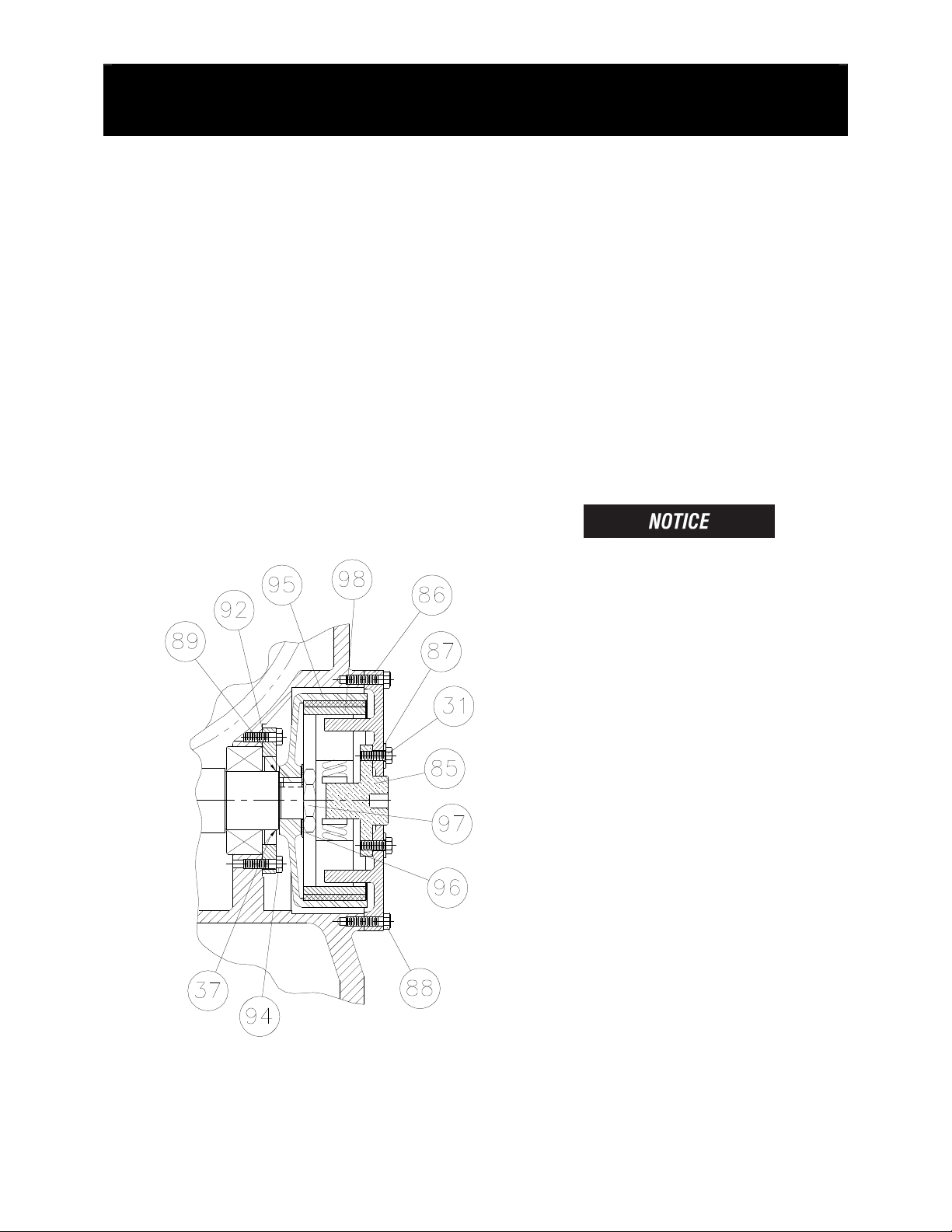
1. Loosen the capscrews (31).
2. Remove the capscrews (88) from the
cover (86).
3. Remove the cover (86) from the
gearbox.
4. Remove the brake shoes (98).
5. Remove the nut (97) and washer
(96).
6. Use the two threaded holes in the
brake drum (95) and a gear puller to
remove the brake drum.
BRAKE DISASSEMBLY
BRAKE DISASSEMBLYBRAKE DISASSEMBLY
7. Inspect parts as follows, replace if
necessary:
A. Inspect the brake shoes (98) for
wear. If the shoe linings are worn
flush with the rivet heads, the
shoes must be replaced.
B. Inspect the brake drum (95) for
severe wear or scoring.
C. Check the inside lower part of the
gearbox housing for the presence
of oil. Replace the seal (37) if oil
is present
If replacing the seal (37), first
drain the oil from the gearbox then
remove the capscrews (94) and
brake cover (93).
10
 Loading...