

Tulp B-Fire 100, B-Fire 100 high, B-Fire 60, B-Fire 80, B-Fire 150 Installation, Servicing And User Instructions Manual
...Page 1
B-Fires Gas
inc.: Standard Fireback, Tunnel and Round
INSTALLATION, SERVICING
AND USER INSTRUCTIONS
For use in GB & IE (United Kingdom and Ireland)
This appliance has been tested and certified for other counties (see technical data). However to install appliance in
other countries, modification of the appliance and its method of installation may be necessary in order to use the
appliance safely and correctly. The manual for the local language must be obtained. Contact Tulp for further
information.
Page 2

Manual Tulp gas fires EN
P. 2
Content
1. General Notes 3
2. User instructions 4
2.1 First Time of Operation 4
2.2 Remote Control Overview 4
2.2.1 Batteries 5
2.2.2 Replacing the batteries 5
2.2.3 Setting the Transmitter code 5
2.2.4 Handset 5
2.3 Cleaning and Maintenance 9
3. Installation instructions. 11
3.1 Gas Connection 11
3.2 Ventilation 11
3.3 Appliance Fireplace Installation 11
3.4 Flue Connection 12
3.5 Fuel Bed Arrangements 17
4. Servicing 18
4.1 Cleaning the Ceramics 18
4.2 Servicing the Burners 18
4.3 Spare parts 19
5. Technical Information 20
5.1 Countries of Use 20
5.2 Technical Data 21
5.3 Dimensions 27
Page 3

Manual Tulp gas fires EN
P. 3
1. General Notes
This Tulp gas appliance is a High Efficiency, Balanced Flue Live Fuel Effect appliance. It provides
radiant and convected heat using the latest burner technology. As well as having a variable heat
output, these fires also utilize a special control system that allows the appliance to use two burners for
high output or a single burner for lower outputs.
One of the burners will be designated as the "Main" Burner, this is the Front, the second burner will be
designated as the "Effect" Burner. The Effect burner can be switched ON or Off whilst the appliance is
alight.
Before Installation, check that the local distribution conditions, nature of the gas and pressure, and
adjustment of the appliance are compatible.
This appliance is intended for use on a gas installation with a governed meter.
This Gas Installation may only be installed by a registered professional competent person (Gas
Safe installer in the UK). The installation must adhere to the requirements of the local and national
Building regulations and national standards. The installation manual must also be followed.
Ensure that the Flue Terminal is not in any way obstructed and is clear of vegetation, i.e. trees, shrubs
etc. and that no objects are leant against the terminal or guard.
Always clean the Window Panel before the fire is ignited. Any finger prints must be removed, as these
will be burnt into the glass and will be un-removable.
Do not operate this appliance if the glass panel has been broken (or cracked), removed or is open.
The appliance is designed to fit numerous installation situations as listed in these installation
instructions. However only flue approved by Tulp for this appliance may be used.
This appliance is a balanced flue product and is room sealed and as such requires no additional
ventilation for operation. However an adequate supply of fresh air to maintain temperatures and a
comfortable environment is recommended.
This appliance is designed as a heating appliance, and as such will get very hot in operation, all
surfaces (except the controls and access door) are considered to be working surfaces and as such
should not be touched. The front windows and surrounds are not considered to be fully secure guards
against accidental contact. It is recommended that an approved fire screen be used if children, the
elderly or persons with limited mobility are to be present in the same area.
Do not place curtains, laundry, furniture etc. within a safe distance of 300mm of this appliance.
Do not attempt to burn rubbish on this appliance.
If this appliance is extinguished, on purpose or other, no attempt to relight should be made within 3
minutes.
Tulp provides a warranty of 24 months on the gas appliances. Warranty requests are only taken in
when sent by the dealer. Warranty expires in the following cases:
Not observing this manuel
Installation not done by a registered professional competent person
Page 4
Manual Tulp gas fires EN
P. 4
2. User instructions.
2.1 First Time of Operation
Before igniting the appliance, ensure that all packaging, safety stickers and any protective wrapping
have been removed, and that the glass has been cleaned, including all fingerprints from the glass.
Ensure that the room is adequately ventilated the first time that the appliance is ignited, we would
recommend opening windows if possible. Run the appliance at full setting for a few hours so that the
paint gets an opportunity to fully cure. During this period it is possible for some fumes and vapours to
be given off. We would recommend keeping children and pets out of the area at this time.
2.2 Remote control overview
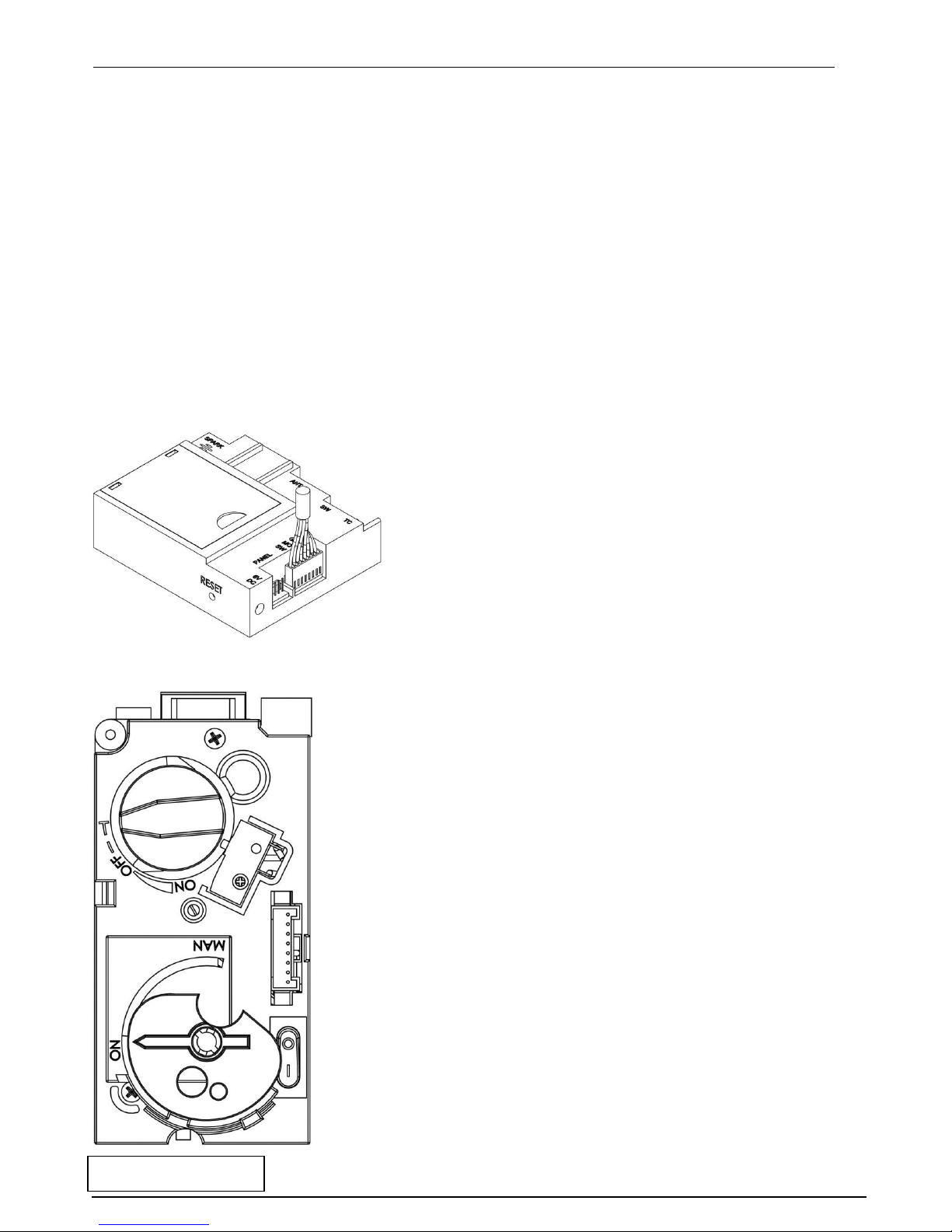
This Tulp Gas appliance has been constructed with an advanced remote control system. This consists of
three main parts: Handset, receiver (fig. 1.1) and gas valve with manual override (fig. 1.2). The gas
control valve and the receiver box are behind the access door. This is also where the product data label
is located.
Fig. 1.1 Receiver
Fig. 1.2 Gas control
With each successful button
press of the handset, the
receiver will emit an audible
signal.
Always leave the dial on the gas
control valve set to “ON”, the
“MAN” position is only for servicing
and emergency use if the handset is
misplaced, or the battery fails.
A toggle switch “0/1” is present on
the gas control valve, this should be
put into the “0” position in the
appliance is not operated for a long
time. Pay attention: when this is on
“0” you cannot operate the fire!!
The heat output can be manually
adjusted by turning the setting knob
on the gas control valve.
Page 5
Manual Tulp gas fires EN
P. 5
2.2.1 Batteries
Remote Handset:3 x 1.5V "AAA" Battery, Quality alkaline recommended
Receiver:4 x 1.5V "AA", Quality alkaline recommended for maximum life.
An alternative AC Mains Adaptor may be used to power the Receiver instead of the 4 AA batteries. Only
an AC Mains Adapter supplied by Tulp may be used. The Mains Adaptor is plugged into the DC 6V
socket on the end of the receiver.
Note - if the AC Mains Adapter is used, remove the 4 AA's from the Receiver, failure to do so could
result in damage and failure of the Receiver. During a period of power outage, the receiver may be
unplugged and batteries returned to the Receiver.
2.2.2 Replacing the batteries
Handset: There is a battery level indicator on the display of the handset. When this gets low remove
the cover on the rear of the handset and replace the battery with another 9V PP3 battery.
Receiver: Three short audible beeps will sound when the appliance is on to indicate that the batteries
in the receiver are getting low.
When the batteries get very low the appliance will be turned off by the remote control. This will fail to
happen if the power supply is interrupted.
To replace the Receiver batteries, slide the cover off of the top of the receiver and use the ribbon to
pull the batteries out. Replace the batteries with new 1.5V AA's, ensuring that the ribbon is located
under the batteries and that the polarity is correct on all 4 batteries.
Never mix new batteries with old, this will result in the new batteries being emptied very quickly.
When the batteries are replaced, it may be necessary to reset the transmitter code, as detailed in the
next section.
2.2.3 Setting the Transmitter code
Press and hold the RESET button with a sharp object (pen or screwdriver) until you hear two audible
beeps. After the second, longer beep, release the RESET button.
Within the next twenty seconds press the down button (Button D fig 1.1) on the remote handset until
you hear an additional long signal confirming the code is set.
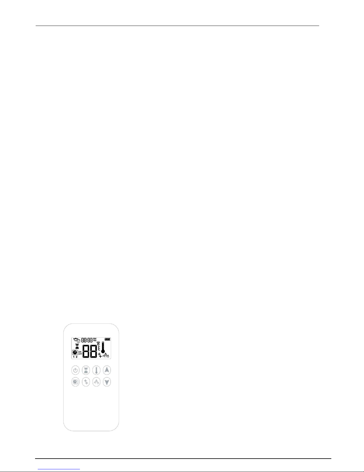
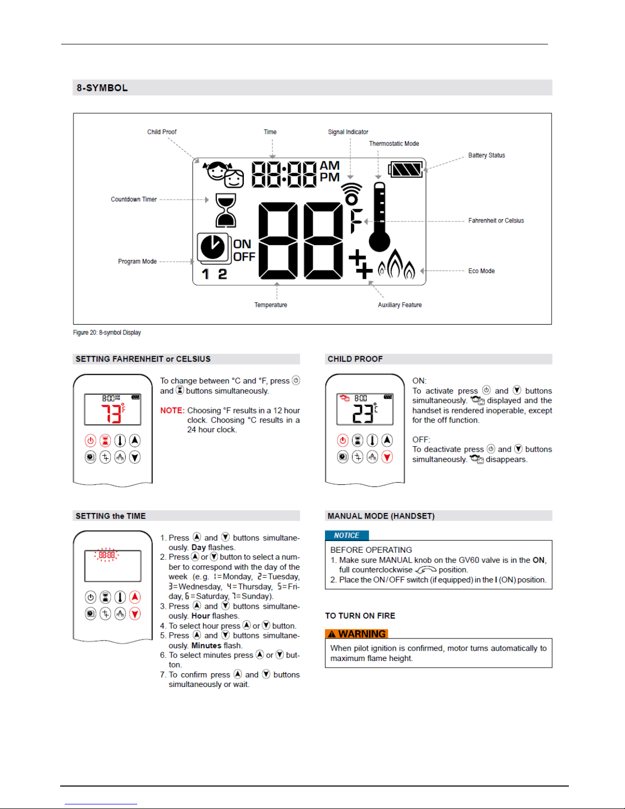
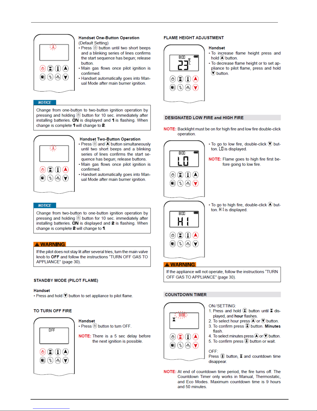
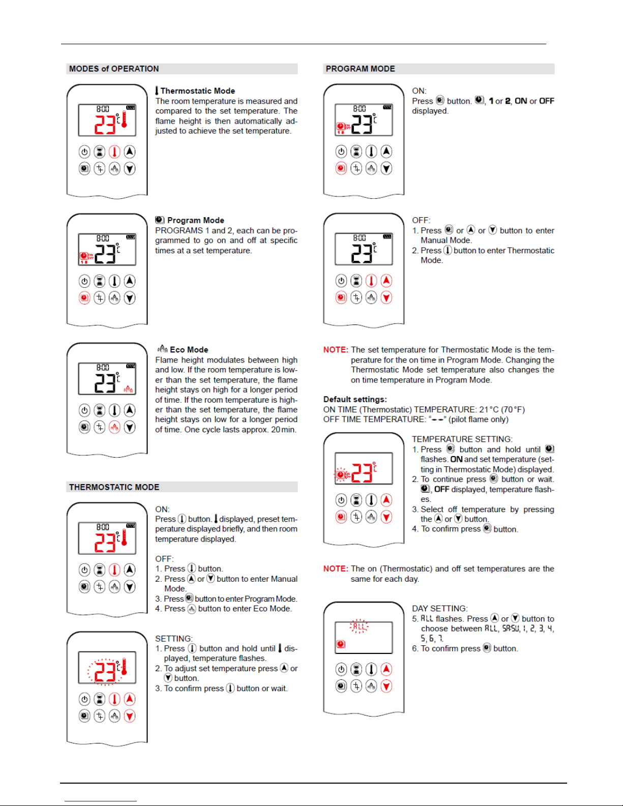
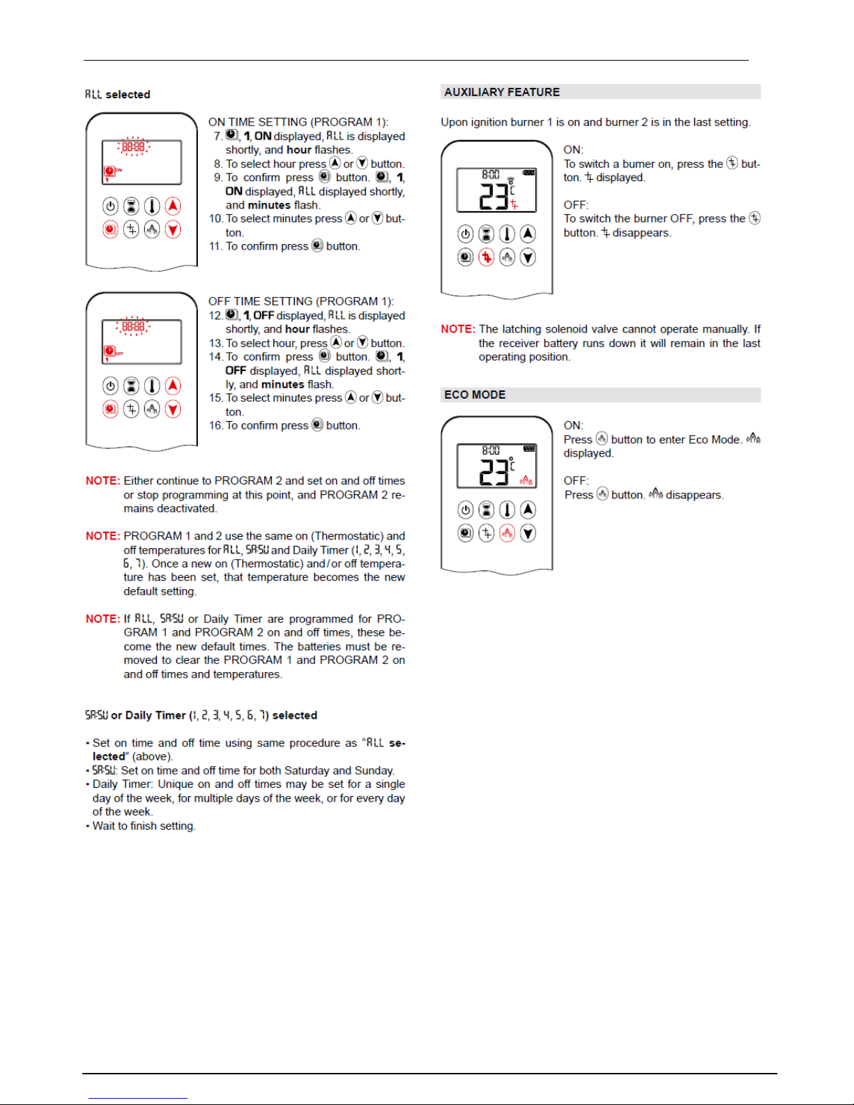
2.2.4 Handset
On the following pages you find an explanation of the handset and all its possibilities.
In paragraph: Handset met 1 knop bediening (pag. 7) wordt uitgelegd
hoe de haard aangezet kan worden!
Page 6
Manual Tulp gas fires EN
P. 6
Page 7
Manual Tulp gas fires EN
P. 7
Page 8
Manual Tulp gas fires EN
P. 8
Page 9
Manual Tulp gas fires EN
P. 9
2.3 Cleaning and Maintenance
This appliance should be inspected and serviced once a year by a qualified, competent and registered
person. The inspection and maintenance must at least ensure that the appliance is working correctly
and safely. It is advisable to clean the appliance of any dust and debris before regularly during the
heating season and especially if the appliance has not been used for some time. This can be done with
a soft brush and a vacuum cleaner or a damp cloth and if required a non-abrasive cleaning agent. Do
not use corrosive or abrasive substances to clean the appliance.
Please pay attention: if you keep pushing the arrow down button the fire will go out but the pilot light
will stay on. It is good to keep the pilot light on because then there is less chance of corrosion!
Page 10
Manual Tulp gas fires EN
P. 10
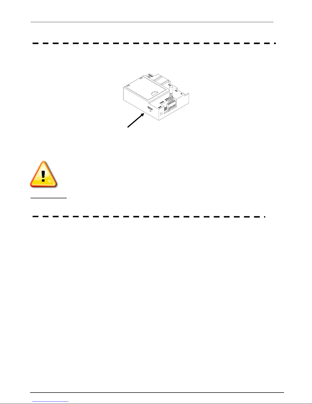
Please pay attention: if the remote does not work, try to push the reset button. This can be done by
using a sharp object.
Pay attention: When the appliance makes a “ploff” during or after igniting it, shut down the appliance
immediately. Before using it again, get in contact with Tulp BV!
Page 11
Manual Tulp gas fires EN
P. 11
3. Installation instructions.
Before commencing Installation, confirm that the details on the appliance data plate correspond to the
local distribution conditions, gas type and pressure to which the appliance is to be installed.
Ensure that gas supply and supply pipe is capable of delivering the required volume and pressure of
gas and is in accordance with the rules in force.
3.1 Gas Connection
This appliance has a gas inlet connection of Ø 12mm.
3.2 Ventilation
This appliance is a Balanced Flue room sealed appliance, and as such needs no additional ventilation.
However an adequate supply of fresh air to maintain temperatures and a comfortable environment is
recommended.
This appliance may be installed in a completely sealed or mechanically ventilated house.
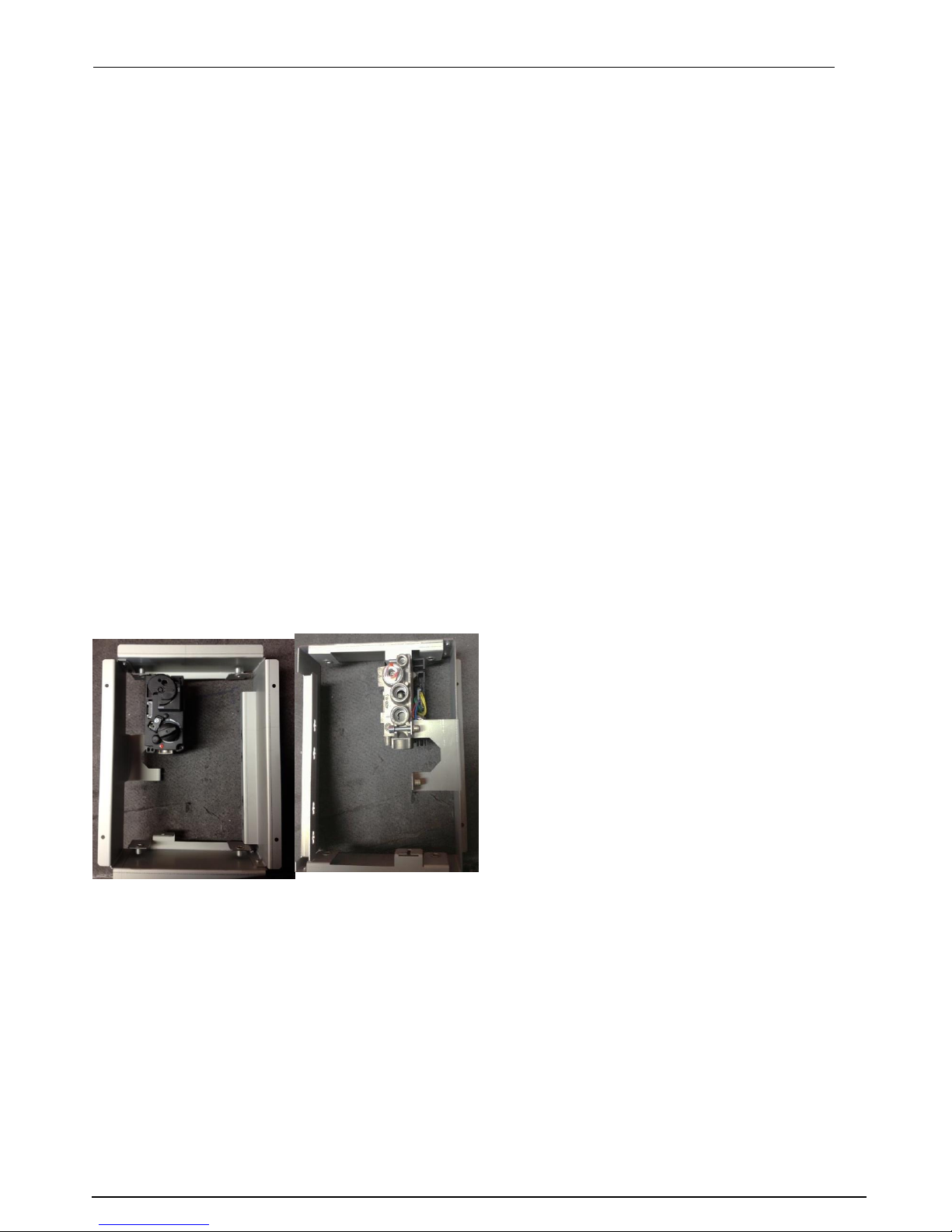
3.3 Appliance Fireplace Installation
Determine the position required for the appliance.
Create a gas connection for the appliance in approximately the correct location for the gas
controls.
The gas controls are connected to the Burner of the appliance. These controls need to be
located in the control access box, so an appropriate position for the access box need to be
determined.
This appliance has fully adjustable legs, these must me set to the desired length before the flue
position is finalized. Fine adjustment of the legs is available via the feet.
Do not make any adjustments to the appliance, except the leg length.
The appliance and Flue system should be fitted with a minimum clearance of 500mm from any
combustible objects or materials, this includes any combustible materials used for the fireplace
construction.
As this is a room sealed appliance and the appliance stands on appropriate legs, a hearth is not
required for this appliance.
The Fireplace should be ventilated with openings giving a total free vent area of 200 cm².
A gap of 50mm should be left all-round the appliance. This also goes for the back of
the appliance!!
If a shelf is to be fitted above the fireplace opening, a gap of 150mm minimum should be left
between the opening and the shelf.
The brackets supplied may be used for securing the appliance to a rear wall.
Page 12

Manual Tulp gas fires EN
P. 12
3.3.1 Building the Fireplace
Construct a studwork fireplace to the desired sizes, minimum sizes are shown in section 3.3.2. Any
combustible material used to construct the Fireplace must not be closer than the minimum dimensions
quoted in section 3.3 above. These dimensions must be observed even if the frame work will be
protected by non-combustible material.
!!! Do not use insulation material (or other) to pack the void around or above the appliance.
!!! Provide ventilation from the fireplace to the minimum amount quoted in 3.3 above.
!!! Provide a cut-out for the Control Access Door.
3.3.2 Built-In Fireplace Sizing
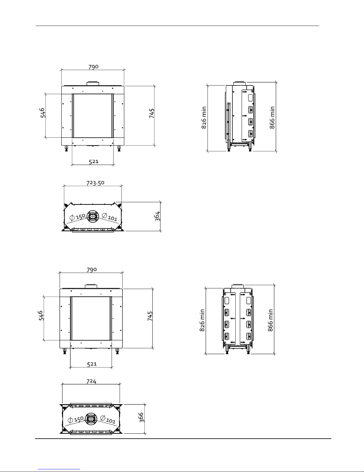
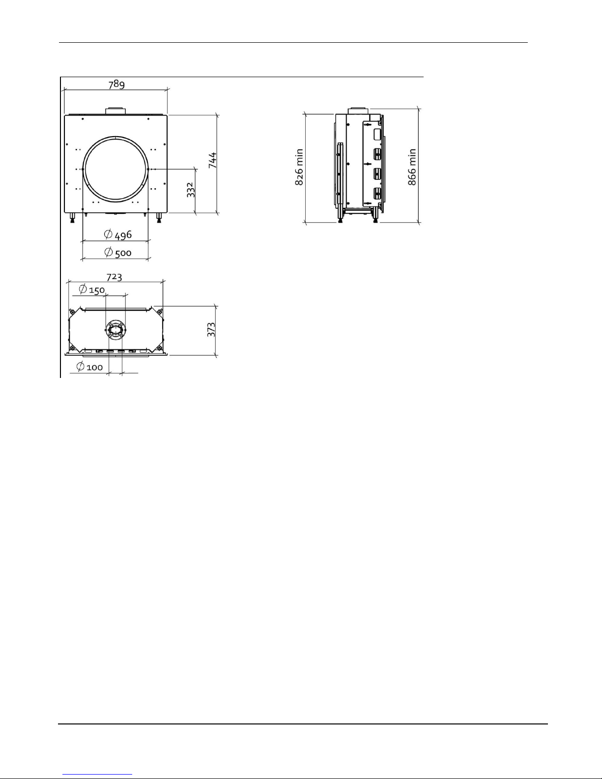
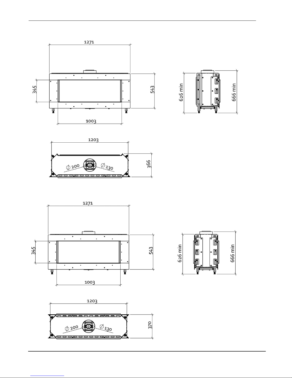
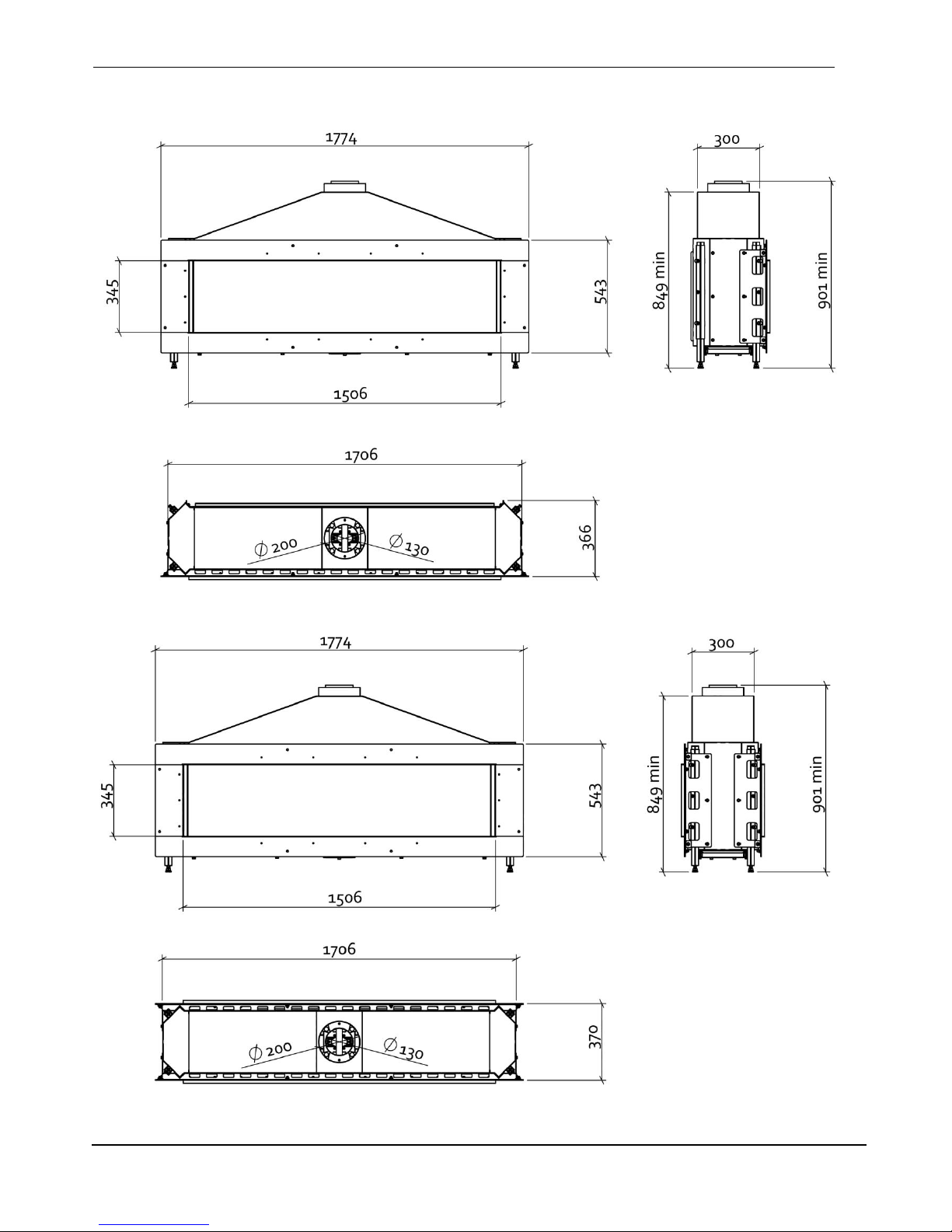
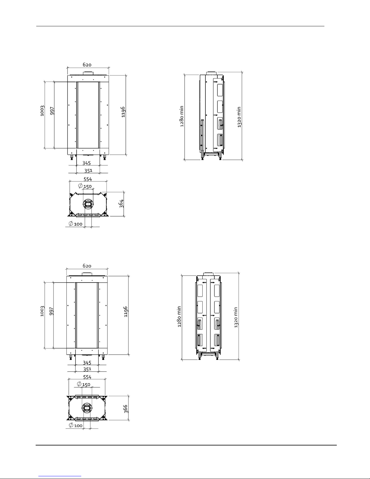
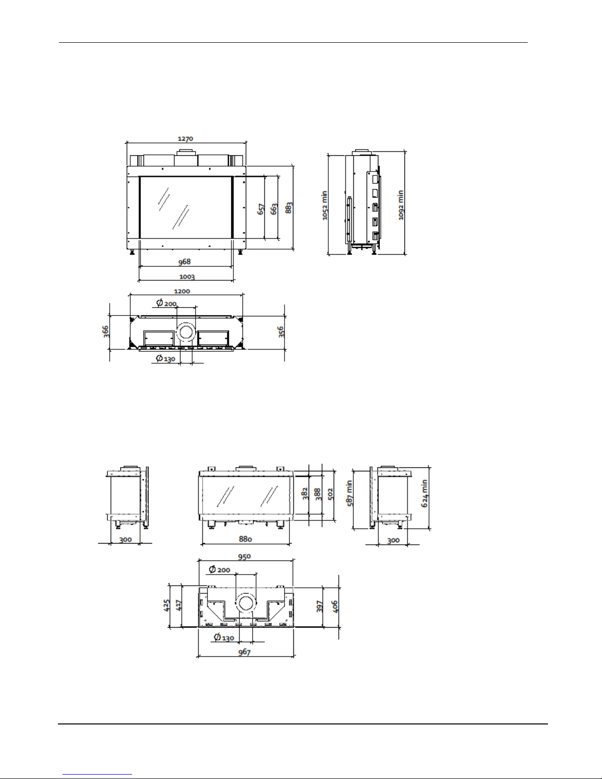
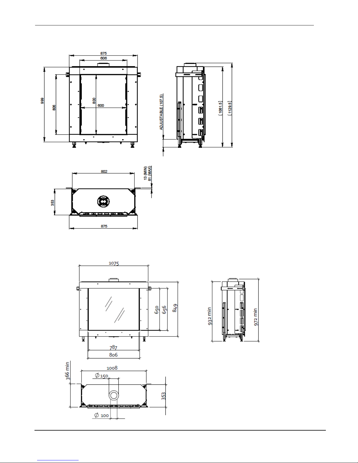
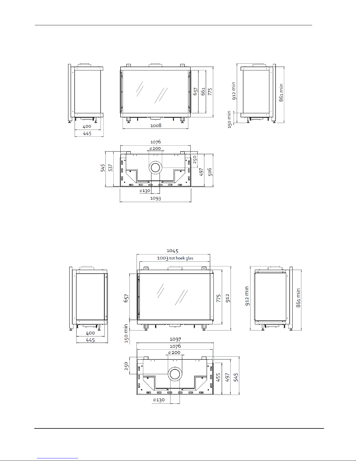
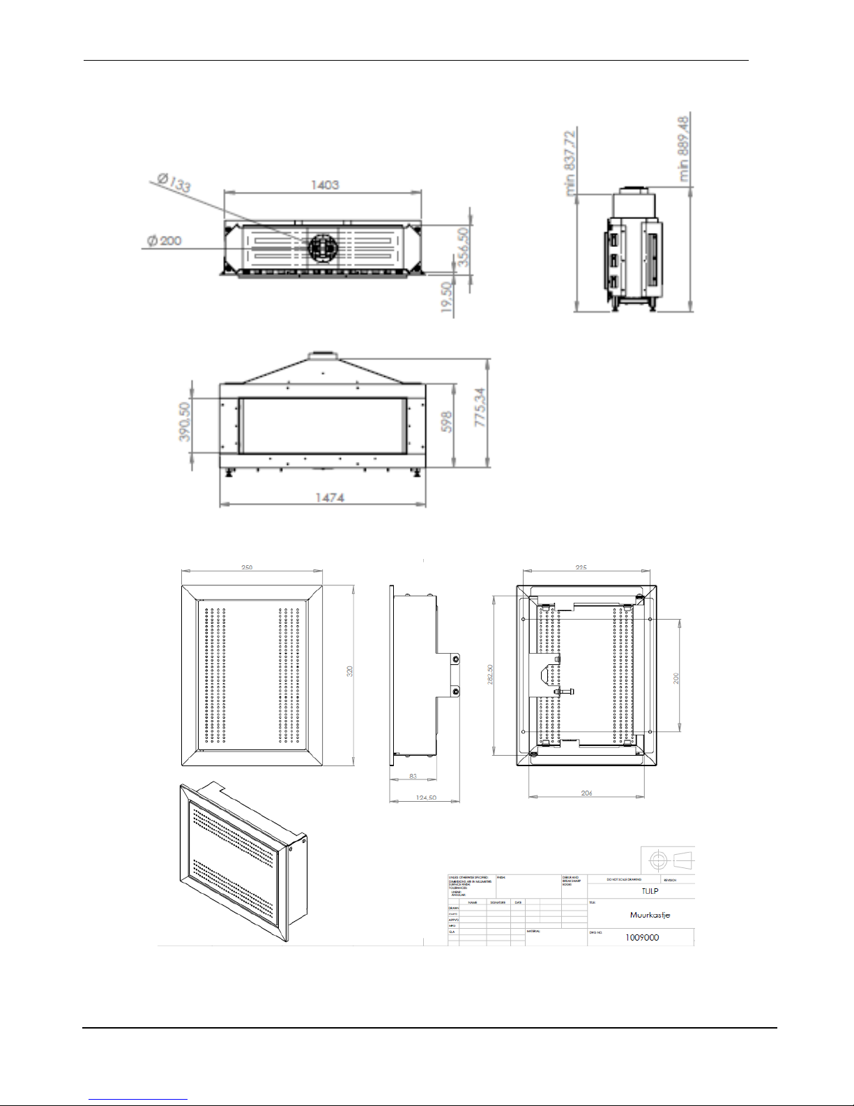
For the sizing of the fireplace we would like to refer to the drawings of the appliances (in the end of
this manual). Also the dimensions of the access door you can find there.
Please look closely at the following points:
Make sure there is a min gap of 2 mm between the appliance and the plasterwork. It is possible
that the appliance expands a bit. If the appliance is built in too tight, the plasterwork will crack.
Take care of enough air inlet (bottom) and outlet (top) in the Fireplace/column. Please look at
paragraph 3.3.
Make sure that the back of the appliance is not against a wall. There should be a gap of at least
50 mm!!
3.4 Flue Connection
3.4.1 General notes
This appliance may be installed with a roof terminal (C31) or a wall terminal (C11).
This appliance may only be used with Balanced Flue (otherwise known as Concentric Flue) parts as
specified by Tulp. The Tulp specified flue parts have been approved with the appliance. If the appliance
is installed on non-Tulp approved parts, Tulp cannot guarantee or accept and responsibility for the
proper and safe working of the appliance.
The flue system must be constructed from the appliance upwards, with all joints being fully locked and
sealed using the Tulp specified parts.
3.4.2 Locating the terminals
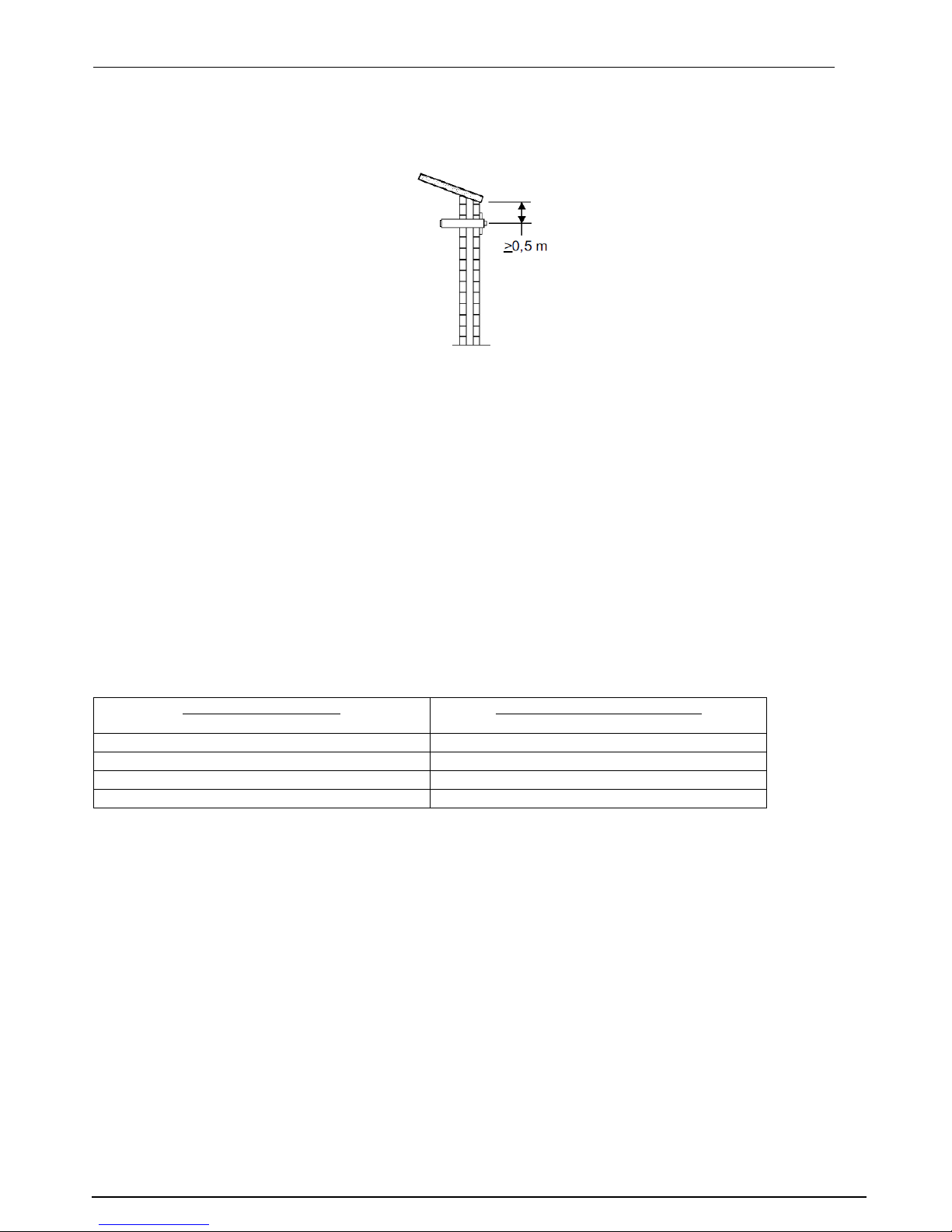
3.4.2.1 Location of the terminal on the roof (vertical).
There should be a minimal 0,5 meter distance between the terminal and the roof edge, with exception
of a possible present ridge edge.
Page 13
Manual Tulp gas fires EN
P. 13
3.4.2.1 Location of a terminal in the wall (horizontal)
There should be a minimal gap of 0,5 m between the terminal and:
Corners of a building
Roof overhang, gutter
Balconies or similar extensions unless the flue construction reaches at least the front of the
balcony or similar extensions.
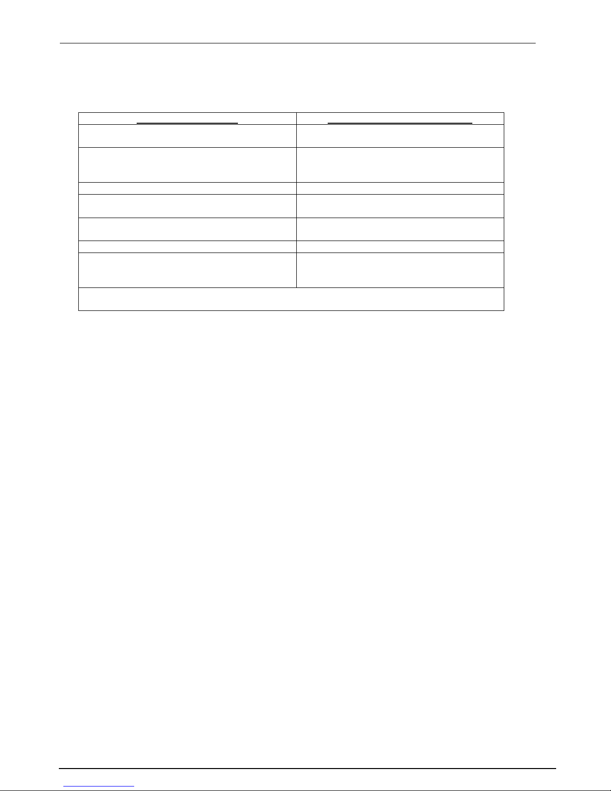
3.4.3 Positioning the terminal to prevent disruption to the environment
This section mentioned distances. These are aiming values! For the exact minimum distances always
consult national and local regulations.
Distance = min distance to avoid nuisance between the terminal and:
A. A vent serving a lounge, toilet or bathroom
B. A combustion air supply, when the combustion air through an occupied space.
C. A movable window that is adjacent to an occupied room, toilet or bathroom.
Terminal on the roof (vertical):
To prevent disruption
Distance: terminal A, B of C
In the same roof
>3 m (*)
In a different roof
>1 m (*)
At a lower wall
>1 m
At a higher wall
>3 m (**)
(*) if it cannot be met, the required distance prevails positioning the outlet.
(**) if it cannot be met, the terminal must be at least 1m above the highest wall / roof hatch.
Page 14
Manual Tulp gas fires EN
P. 14
Terminal in the wall (horizontal:
To prevent disruption
Distance: terminal to A, B of C
At walls in multi-storey buildings
Not permitted when A, B of C is above
the terminal
At walls – in general. (*)
Above terminal: >2m
Below terminal: >0,75m
Left and right of terminal: >0,75 m
At <1m of roof edge.
>2m
Below balconies, galleries etc
>2m to underside of the protruding
balcony or gallery
Under balconies, walkways and the
terminal extends to the front
>2m
In the garden or at the terrace
>2m to outdoor (**)
Relative to a facing wall
>2m (if the distance to the opposite wall
is less, applies to both facades the
conditions given in "wall-general")
Check with your local gas company for the requirements relating to outlets in two
opposite walls and outlet (s) in wall (s) that form an angle.
(*) This minimal distances do not apply if there is an obstruction, which protrudes at least 0.5 m
from the wall and has a length which is greater than the distance between the outlets A, B, or C
(**) This distance is not required if the outlet is at least 1m higher than the referred area from
outside is.
Outlets at a distance of less than 2m above and less than 0.5 m measured horizontally from the hard
surface of a public area placed must have an effective protector. This shielding may not affect the
proper functioning of the device.
3.4.4 Horizontal terminal type C11
Flue sizes:
B-Fire 35, 50, 60, 80 : Ø100/150
B-Fire 95, 100, 100H : Ø130/200
B-Fire 150, B-Fire 120 : Ø130/200
Page 15
Manual Tulp gas fires EN
P. 15
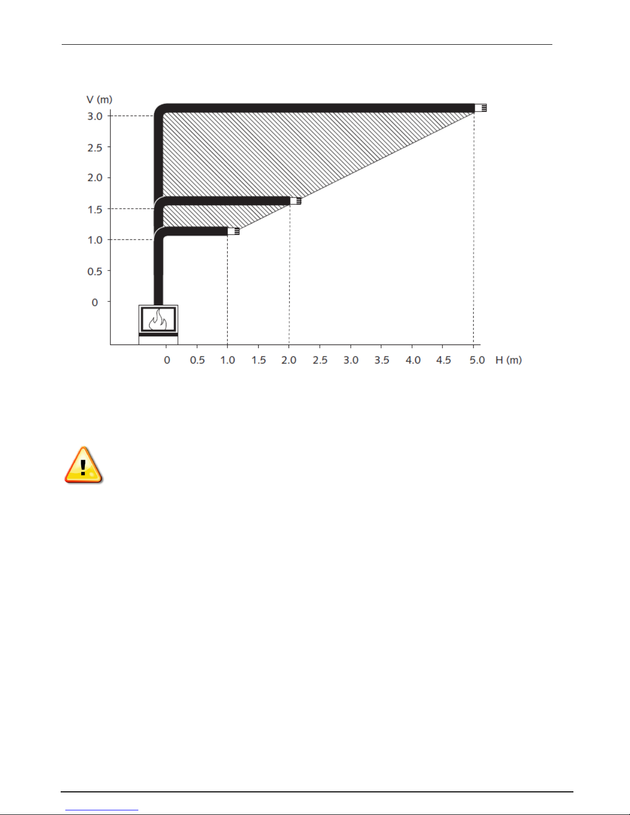
Maximum pipe extension, for outside wall.
Use shaded area to calculate maximum allowable length (H) for the corresponding pipe rise (V) but pay
attention to values below!!
Page 16

Manual Tulp gas fires EN
P. 16
3.4.7 Vertical Roof Vent Termination C31
Flue sizing:
B-Fire Gas 35 : straight up: 30mm flue restrictor, Ø100/150 – 0,5m minimum
with bends: no flue restrictor, Ø100/150
B-Fire Gas 50, 60, 80 : straight up: 30mm flue restrictor, Ø100/150 – 1,0m minimum
with bends: no flue restrictor, Ø100/150
B-Fire Gas 95, 100, 100H : straight up: use Ø100/150 – 1,0m minimum
up with max 2x 45 bend: use Ø100/150
up with bends: use Ø200/130
B-Fire Gas 150 : straight up, min 2 meter: use Ø100/150
Up with bends: Ø130/200
B-Fire Gas 120 :
When incorporating and horizontal flue runs, these horizontal runs must be less than 0.5 times the
overall flue height.
Page 17
Manual Tulp gas fires EN
P. 17
3.5 Fuel Bed Arrangements.
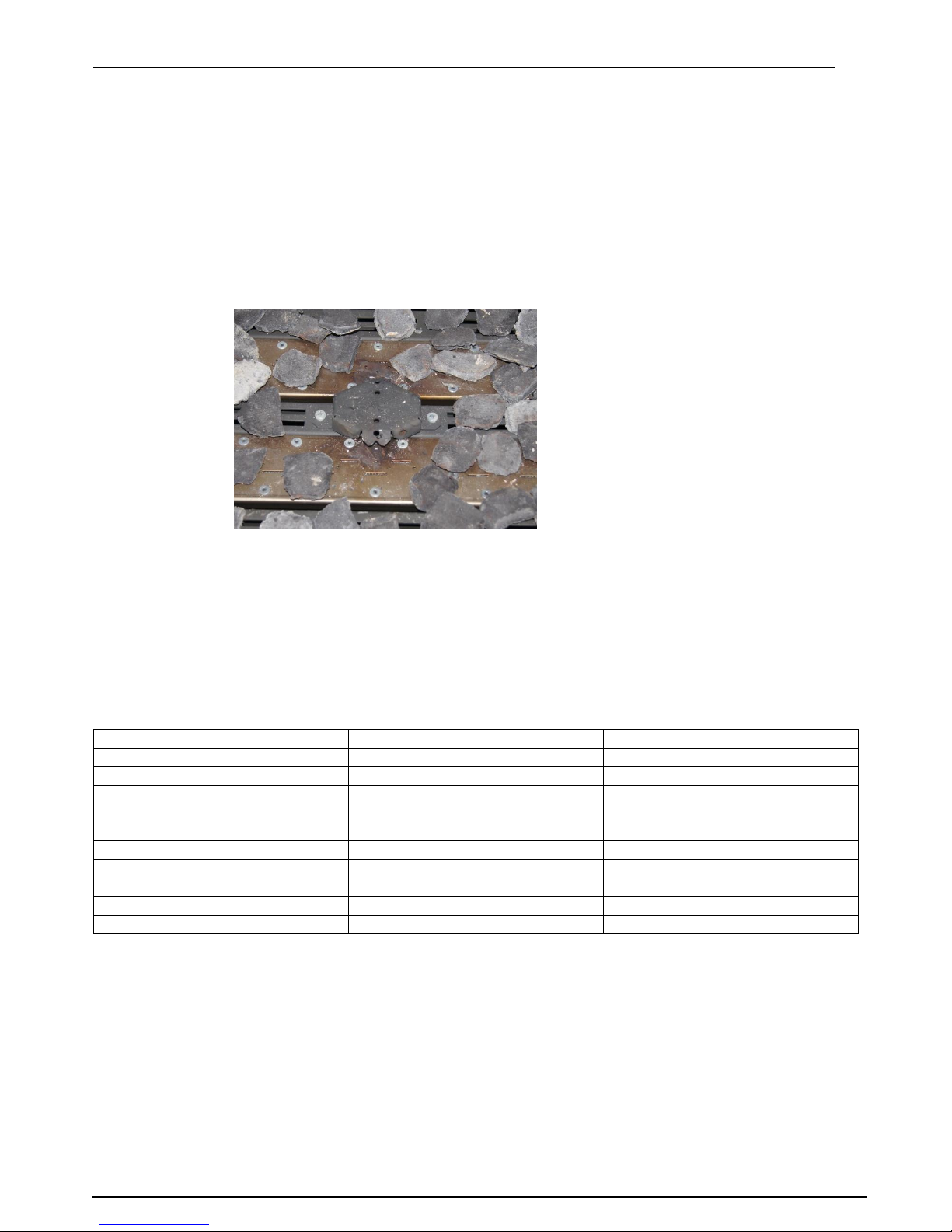
With the appliance a colour copy is delivered. Here you see how the logs should be placed. Do not use
another arrangement of the logs! This can cause soot!
White and black pebbles must be shattered evenly over the grate.
Pay attention: always make sure that the pilot light is free and not blocked! This goes for as
well the logs as the pebbles!
Pay attention: when using LPG/Propane do not put chips or black or white pebbles on top of
the burners. The burners must be completely open!
Below you see what you can use for all appliances:
Log set
Pebbles (white or black)
B-fire 35
Possible
Possible
B-fire 50
Possible
Possible
B-fire 60
Possible
Possible
B-fire 80
Possible
Possible
B-fire 95
Possible
Possible
B-fire 100
Possible
Possible
B-fire 100H
Possible
Possible
B-fire 100H 3 sided open/corner
Possible
Not possible
B-fire 150
Possible
Possible
B-fire 120
Possible
Possible
Page 18

Manual Tulp gas fires EN
P. 18
4. Servicing
Turn the appliance OFF and isolate the gas supply. Ensure the appliance is fully cold before attempting
to start servicing the appliance. No liability can be accepted by Tulp for injury caused by burning or
scolding by a hot appliance.
A suggested procedure for servicing is listed below.
A. Lay out dust sheet on flooring, mask off any special fireplace materials.
B. Remove Side Window Trims
C. Remove Bottom Window Trim
D. Remove Window Assembly
E. Carefully remove the Ceramic components (including Embers) or Gravels
F. Use a Vacuum cleaner to clean the top of the burners and grate
G. Remove Grate
H. Remove both Burner Top assemblies, there are 3 M6 flange bolts holding each in
I. Using a vacuum cleaner, fully clean both Burner Top.
J. With the Burner Tops now removed, the Pilot and the heads of the injectors are clearly visible.
Use the vacuum cleaner and a soft brush to clean the pilot assembly and both Injectors. Never
modify or bend the Thermocouple
K. Replace both burner top assemblies and fix in with the fixings
L. Turn on the gas supply and check for leaks, check the burners and Pilot for good condition and
operation
M. Replace Grate
N. Replace the Firebed arrangements
O. Replace Window Assembly and Trims
P. Check the flue system and terminal, making sure that the terminal vent is fully clear
Q. Light the appliance and test setting pressures
R. Check the safe operation of the appliance.
4.1 Cleaning the Ceramics
Remove the ceramics as detailed in A - E above.
Gently clean the ceramics in the open air, using a soft brush and a vacuum cleaner. Where necessary
replace damaged components only with genuine Tulp specified parts. Seal any scrap ceramics in plastic
bags and dispose at proper refuse sites. When using a vacuum cleaner, it is recommended that one
with a HEPA filtering system is used.
Re-fit the Fire bed arrangement, re-seal the appliance and check the safe operation of the appliance.
4.2 Servicing the Burners
Remove the Burner Top Assemblies as detailed in A - H above.
The pilot is now clearly visible, the pilot, including the Thermocouple, can be replaced/serviced by
removing raising the pilot assembly from its mounting. This is done by removing the two nuts (M4,
7mm spanner) on the surface of the pilot. The fittings on the under-side of the pilot can be un-done
using a 10mm spanner where appropriate.
To access the Main Burner Injectors, the Burner base units must be removed. This is done by removing
the four bolts (M6, 10mm spanner) holding the burner in. With these four bolts removed, the Burner
base can be raised up through the Firebox, and the Injectors can be easily accessed.
When replacing any parts use only original Tulp specified parts.
Page 19

Manual Tulp gas fires EN
P. 19
4.3 Spare parts
Item B-fire S-fire
Pilot Assembly Natural 0_160_032-NAT51 0_160_035-NAT51
Pilot Assembly LPG 0_160_032-LPG30 0_160_035-LPG30
Elektrode 0_915_015 0_915_015
Elektrode lead G60-ZKIS1/1500 G60-ZKIS1/1500
Thermocouple 1_000_2150 1_000_2150
Gas valve 1_ GV60 1_ GV60
Latching Solenoid GV-S60C/12
(for double burner)
Receiver box G6R-R4AU G6R-R4AU
Handset G6R-H4T2FW-T G6R-H4T2FW-T
Access Door Assembly 1_000_9000 1_000_9000
Page 20

Manual Tulp gas fires EN
P. 20
5. Technical Information
5.1 Countries of Use
Land
Aardgas
Propaan
AT -Austria
I2H, G20 at 20 mbar
I
3P(50)
,G31 at 50 mbar; I
3B/P(50)
,G30/G31
at 50 mbar
BE -Belgium
I
2E+
, G20/G25 at 20/25 mbar
I3+,G31/G31 at 28/37 mbar; I
3P(37)
,G31
at 37 mbar; I
3B/P(30)
,G30/G31 at 30
mbar
BG -Bulgaria
I2H, G20 at 20 mbar
I
3B/P(30)
,G30/G31 at 30 mbar
CH - Switzerland
I2H, G20 at 20 mbar
I
3P(50)
,G31 at 50 mbar; I3+,G31/G31 at
28/37 mbar; I
3P(37)
,G31 at 37 mbar;
I
3B/P(50)
,G30/G31 at 50 mbar
CY -Cyprus
I2H, G20 at 20 mbar
I3+,G31/G31 at 28/37 mbar;
I
3B/P(30)
,G30/G31 at 30 mbar
CZ -Czech Republic
I2H, G20 at 20 mbar
I
3P(50)
,G31 at 50 mbar; I3+,G31/G31 at
28/37 mbar; I
3P(37)
,G31 at 37 mbar;
I
3B/P(50)
,G30/G31 at 50 mbar
DE -Germany
I
2ELL
, G25 at 20 mbar; I2E, G20 at 20
mbar
I
3P(50)
,G31 at 50 mbar; I
3B/P(50)
,G30/G31
at 50 mbar
DK -Denmark
I2H, G20 at 20 mbar
I
3B/P(30)
,G30/G31 at 30 mbar
EE -Estonia
I2H, G20 at 20 mbar
I
3B/P(30)
,G30/G31 at 30 mbar
ES -Spain
I2H, G20 at 20 mbar
I3+,G31/G31 at 28/37 mbar; I
3P(37)
,G31
at 37 mbar
FI -Finland
I2H, G20 at 20 mbar
I
3P(30)
,G31 at 30 mbar; I
3B/P(30)
,G30/G31
at 30 mbar
FR -France
I
2E+
, G20/G25 at 20/25 mbar
I3+,G31/G31 at 28/37 mbar; I
3P(37)
,G31
at 37 mbar; I
3B/P(30)
,G30/G31 at 30
mbar; I
3B/P(50)
,G30/G31 at 50
GB -United Kingdom
I2H, G20 at 20 mbar
I3+,G31/G31 at 28/37 mbar; I
3P(37)
,G31
at 37 mbar; I
3B/P(30)
,G30/G31 at 30
mbar
GR -Greece
I2H, G20 at 20 mbar
I3+,G31/G31 at 28/37 mbar; I
3P(37)
,G31
at 37 mbar; I
3B/P(30)
,G30/G31 at 30
mbar
HU -Hungary
I
3B/P(30)
,G30/G31 at 30 mbar
HR -Croatia
I2H, G20 at 20 mbar
I
3P(37)
,G31 at 37 mbar; I
3B/P(30)
,G30/G31
at 30 mbar
IE -Ireland
I2H, G20 at 20 mbar
I3+,G31/G31 at 28/37 mbar; I
3P(37)
,G31
at 37 mbar
IS -Iceland
IT -Italy
I2H, G20 at 20 mbar
I3+,G31/G31 at 28/37 mbar; I
3P(37)
,G31
at 37 mbar; I
3B/P(30)
,G30/G31 at 30
mbar
LT -Lithuania
I2H, G20 at 20 mbar
I3+,G31/G31 at 28/37 mbar; I
3P(37)
,G31
at 37 mbar; I
3B/P(30)
,G30/G31 at 30
mbar
LU -Luxembourg
I2E, G20 at 20 mbar
LV -Latvia
I2H, G20 at 20 mbar
MT -Malta
I
3B/P(30)
,G30/G31 at 30 mbar
NL -The Netherlands
I2L, G25 at 25 mbar
I
3P(50)
,G31 at 50 mbar; I
3P(30)
,G31 at 30
mbar; I
3P(37)
,G31 at 37 mbar;
I
3B/P(30)
,G30/G31 at 30 mbar
NO -Norway
I2H, G20 at 20 mbar
I
3B/P(30)
,G30/G31 at 30 mbar
PL -Poland
I2E, G20 at 20 mbar
I
3P(37)
,G31 at 37 mbar
PT -Portugal
I2H, G20 at 20 mbar
I3+,G31/G31 at 28/37 mbar; I
3P(37)
,G31
at 37 mbar
RO -Romania
I2E, G20 at 20 mbar
I
3P(30)
,G31 at 30 mbar; I
3B/P(30)
,G30/G31
at 30 mbar
SE - Sweden
I2H, G20 at 20 mbar
I
3B/P(30)
,G30/G31 at 30 mbar
SL -Slovenia
I2H, G20 at 20 mbar
I3+,G31/G31 at 28/37 mbar; I
3P(37)
,G31
at 37 mbar; I
3B/P(30)
,G30/G31 at 30
mbar
SK -Slovakia
I2H, G20 at 20 mbar
I
3P(50)
,G31 at 50 mbar; I3+,G31/G31 at
28/37 mbar; I
3P(37)
,G31 at 37 mbar;
I
3B/P(30)
,G30/G31 at 30 mbar;
I
3B/P(50)
,G30/G31 at 50 mbar
TR -Turkey
I2H, G20 at 20 mbar
I3+,G31/G31 at 28/37 mbar; I
3P(37)
,G31
at 37 mbar; I
3B/P(30)
,G30/G31 at 30
mbar
Page 21

Manual Tulp gas fires EN
P. 21
5.2 Technical Data
5.2.1 B-Fire 50 (round) (PIN: 0558CL1179)
Type
C11/C31
Gas type
G20
G20/G25
G25
G30/G31
G30/G31
G31
I2H,I2E,I2E+
I2ELL
I2L
I3B/P(30/50)
I3+
I3P(30,37,50)
Supply Pressure
mbar
20
20
25
30/50
28-30/37
30/37/50
Nominal Heat Input
Gross (Hs)
kW
12
12.0/9.8
11 9 9
8
Output
kW
7.5
6.8/5.5
6.9
5.6
5.6
5.0
Consumption
m³/hr
1.143
1.143/1.085
1.218
0.257
0.257
0.301
Burner Pressure (hot)
mbar
12.7
12.7
15.7
28.8
28.8
29.9
Injector Marking (x2)
480
120
Pilot
0.160.032-51
0.160.032-30
Efficiency Class
2
Nox Class
4
5.2.2 B-Fire 100 (PIN 0558CL1179)
Type
C11/C31
Gas type
G20
G20/G25
G25
G30/G31
G30/G31
G31
I2H,I2E,I2E+
I2ELL
I2L
I3B/P(30/50)
I3+
I3P(30,37,50)
Supply Pressure
mbar
20
20
25
30/50
28-30/37
30/37/50
Nominal Heat Input
Gross (Hs)
kW
14
14/11.4
12.8 9 9
8
Output
kW
8.8
8.8/7.2
8.0
5.6
5.6
5.0
Consumption
m³/hr
1.333
1.333/1.262
1.417
0.257
0.257
0.301
Burner Pressure (hot)
mbar
10.8
10.8
13.6
28.9
28.9
29.7
Injector Marking (x2)
560
120
Pilot
0.160.032-51
0.160.032-30
Efficiency Class
2
Nox Class
4
Page 22

Manual Tulp gas fires EN
P. 22
5.2.3 B-Fire 150 (PIN 0558CL1179)
Type
C11/C31
Gas type
G20
G20/G25
G25
G30/G31
G30/G31
G31
I2H,I2E,I2E+
I2ELL
I2L
I3B/P(30/50)
I3+
I3P(30,37,50)
Supply Pressure
mbar
20
20
25
30/50
28-30/37
30/37/50
Nominal Heat Input
Gross (Hs)
kW
19
19/15.6
17.5
13
13
11.5
Output
kW
12.1
12.1/10
11.5
9.0
9.0
8.0
Consumption
m³/hr
1.809
1.809/1.727
1.938
0.372
0.372
0.432
Burner Pressure (hot)
mbar
5.6
5.6
6.9
28.6
28.6
29.6
Injector Marking (x2)
1200
160
Pilot
0.160.032-51
0.160.032-30
Efficiency Class
2
Nox Class
5
5.2.4 B-Fire 35 (PIN 0558CL1179)
Type
C11/C31
Gas type
G20
G20/G25
G25
G30/G31
G30/G31
G31
I2H,I2E,I2E+
I2ELL
I2L
I3B/P(30/50)
I3+
I3P(30,37,50)
Supply Pressure
mbar
20
**
25
30/50
28-30/37
30/37/50
Nominal Heat Input
Gross (Hs)
kW
12
**
11
8.8
8.8
7.8
Output
kW
7.5
**
6.9
5.6
5.6
4.9
Consumption
m³/hr
1.114
**
1.218
0.252
0.252
0.293
Burner Pressure (hot)
mbar
13
**
16.1
28.6
28.6
29.6
Injector Marking (x2)
480
120
Pilot
0.160.032-51
0.160.032-30
Efficiency Class
2
Nox Class
5
Page 23

Manual Tulp gas fires EN
P. 23
5.2.5 B-Fire 95 (PIN 0558CM1360)
Type
C11/C31
Gas type
G20
G20/G25
G25
G30/G31
G30/G31
G31
I2H,I2E,I2E+
I2ELL
I2L
I3B/P(30/50)
I3+
I3P(30,37,50)
Supply Pressure
mbar
20
20
25
30/50
28-30/37
30/37/50
Nominal Heat Input
Gross (Hs)
kW
13.2
13.2/10.8
12.2
10.2
10.2
9.0
Output
kW
9.0
9.0/7.4
8.4
7.0
7.0
6.2
Consumption
m³/hr
1.257
1.336
1.194
0.289
0.289
0.335
Burner Pressure (hot)
mbar
16,8
20.7
16.5
28.6
28.6
29.6
Injector Marking (x2)
480
120
Pilot
0.160.032-51
0.160.032-30
Efficiency Class
2
Nox Class
5
5.2.6 B-Fire 100 high (front) (PIN 0558CM1360)
Type
C11/C31
Gas type
G20
G20/G25
G25
G30/G31
G30/G31
G31
I2H,I2E,I2E+
I2ELL
I2L
I3B/P(30/50)
I3+
I3P(30,37,50)
Supply Pressure
mbar
20
20
25
30/50
28-30/37
30/37/50
Nominal Heat Input
Gross (Hs)
kW
16.3
16.3/13.2
14.8
11.2
11.2
9.8
Output
kW
11.2
11.2/9.4
10.1
7,7
7.7
6.8
Consumption
m³/hr
1.532
1.532/1.442
1.614
0.317
0.317
0.366
Burner Pressure (hot)
mbar
6,5
6,5
8.0
28.6
28.6
29.6
Injector Marking (x2)
650
140
Pilot
0.160.032-51
0.160.032-30
Efficiency Class
2
Nox Class
4
Page 24

Manual Tulp gas fires EN
P. 24
5.2.7 B-Fire 60 (PIN 0359CO1331)
Type
C11/C31
Gas type
G20
G20/G25
G25
G30/G31
G30/G31
G31
I2H,I2E,I2E+
I2ELL
I2L
I3B/P(30/50)
I3+
I3P(30,37,50)
Supply Pressure
mbar
20
20
25
30/50
28-30/37
30/37/50
Nominal Heat Input
Gross (Hs)
kW
15.0
15.0
15.0
11.0
11.0
11.0
Output
kW
10,3
10,3
10,3
7.5
7.5
7.5
Consumption
m³/hr
Burner Pressure (hot)
mbar
13.1
13.1
18.9
20.6
20.6
29.0
Injector Marking (x2)
560
180
Pilot
0.160.032-51
0.160.032-30
Efficiency Class
2
Nox Class
5
5.2.8 B-Fire 80 (PIN 0359CO1331)
Type
C11/C31
Gas type
G20
G20/G25
G25
G30/G31
G30/G31
G31
I2H,I2E,I2E+
I2ELL
I2L
I3B/P(30/50)
I3+
I3P(30,37,50)
Supply Pressure
mbar
20
20
25
30/50
28-30/37
30/37/50
Nominal Heat Input
Gross (Hs)
kW
15.0
15.0
15.0
11.0
11.0
11.0
Output
kW
10,3
10,3
10,3
7.5
7.5
7.5
Consumption
m³/hr
Burner Pressure (hot)
mbar
13.1
13.1
18.9
20.6
20.6
29.0
Injector Marking (x2)
560
180
Pilot
0.160.032-51
0.160.032-30
Efficiency Class
2
Nox Class
5
Page 25

Manual Tulp gas fires EN
P. 25
5.2.9 B-Fire 100 high 3 siden open of corner open (PIN 0063CO3576)
Type
C11/C31
Gas type
G20
G20/G25
G25
G30/G31
G30/G31
G31
I2H,I2E,I2E+
I2ELL
I2L
I3B/P(30/50)
I3+
I3P(30,37,50)
Supply Pressure
mbar
20
20
25
Nominal Heat Input
Gross (Hs)
kW
16.0
16.0/13.2
14.7
Output
kW
Consumption
m³/hr
12.4
12.4
15.4
Burner Pressure (hot)
mbar
20
20
25
Injector Marking (x2)
650
Pilot
0.160.032-51
Efficiency Class
2
Nox Class
5
5.2.10 B-Fire 120
Type
C11/C31
Gas type
G20
G20/G25
G25
G30/G31
G30/G31
G31
I2H,I2E,I2E+
I2ELL
I2L
I3B/P(30/50)
I3+
I3P(30,37,50)
Supply Pressure
mbar
20
20
25
30/50
28-30/37
30/37/50
Nominal Heat Input
Gross (Hs)
kW
16,5
16,5
15,4
13,1
13,1
11,3
Consumption
m³/hr
1,600
1,600
1,604
0,370
0,370
0,427
Burner Pressure (hot)
mbar
13,2
13,2
15,8
18,8
18,8
19,5
Injector Marking (x2)
650
220
Pilot
0.160.032-51
0.160.032-30
Efficiency Class
2
Nox Class
5
Page 26
Manual Tulp gas fires EN
P. 26
5.3 Dimensions
5.3.1 B-Fire Gas 50
5.3.2 B-Fire Gas 50 Tunnel
Page 27
Manual Tulp gas fires EN
P. 27
5.3.3 B-Fire Gas 50 Round
Page 28
Manual Tulp gas fires EN
P. 28
5.3.4 B-Fire Gas 100
5.4.5 B-Fire Gas 100 Tunnel
Page 29
Manual Tulp gas fires EN
P. 29
5.4.6 B-Fire Gas 150
5.4.7 B-Fire Gas 150 Tunnel
Page 30
Manual Tulp gas fires EN
P. 30
5.4.8 B-Fire Gas 35
5.4.9 B-Fire Gas 35 Tunnel
Page 31
Manual Tulp gas fires EN
P. 31
5.4.10 B-fire 100 high
5.4.11 B-fire 95 3 sides open, right open, left open
Page 32
Manual Tulp gas fires EN
P. 32
5.4.12 B-fire 60
5.4.13 B-fire 80
Page 33
Manual Tulp gas fires EN
P. 33
5.4.14 B-fire 100H 3 sided open
5.4.15 B-fire 100H corner open
Page 34
Manual Tulp gas fires EN
P. 34
5.4.16 B-fire 120
5.4.17 Toegangsluikje
Page 35

Manual Tulp gas fires EN
P. 35
Remarks:
Page 36

Manual Tulp gas fires EN
P. 36
STUV sa
rue Jules Borbouse, 4 B-5170 Bois-de-Villers
Belgium
Tel. : +32 (0)81 43 47 96
Fax. : +32 (0)81 43 48 74
Web : www.stuv.com
Email : [email protected]
TULP B.V.
Ganzestaartsedijk 1 5525 KC Duizel
The Netherlands
Tel. : +31 (0)497 511 299
Fax. : +31 (0)497 535 062
Web : www.tulp.eu
Email : [email protected]
 Loading...