

Page 1
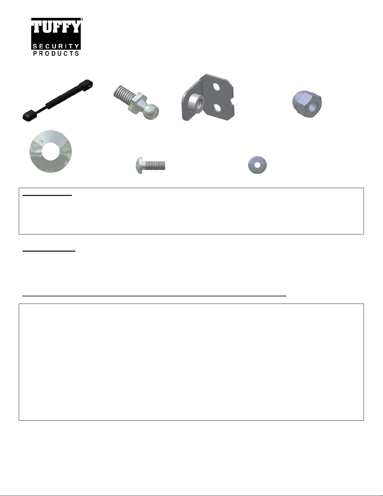
SHIPPING PACKAGE CHECKLIST
INSTALLATION INSTRUCTIONS
GAS STRUT 7 ½” WITH 2” STROKE #863
Call (970) 564-1762 for Technical Support
#3 Gas Strut #4 – (2) Ball Stud #7 - (2) Brackets #5 - 5/16-18 CAP NUT
#6 - 5/16” WASHER #2 – (4) 10-32 X ½” PHILLIPS SCREW #1 – (4) 10-32 HEX WASHER NUT
TOOLS NEEDED
• Phillips head screw driver (Short)
• 3/8” Nut-driver and/or wrench
• ½” Socket and ratchet
• ½” Wrench
ATTENTION: When these instructions and drilling locations are followed on a
Tuffy console with a standard hinge configuration the lid will open up 90 degrees
and stop. If you desire a different lid stopping angle or have a non-standard
hinge configuration the hole locations will need to be adjusted.
PLEASE READ ALL INSTRUCTIONS THOROUGHLY BEFORE STARTING INSTALLA TION.
INSTRUCTIONS TO MOUNT THE GAS STRUT ASSEMBLY IN TUFFY CONSOLES WITH A STANDARD LID
CONFIGURATION (SEE BELOW FOR NON-STANDARD PART# 139 JK CONSOLE INSERT LID INSTALLATION)
1. Remove the padded cushion and mark the spots for (2) ¼” holes in lid to mount the #7 Bracket. Measure from the rear and right
side on the outside top of the lid as illustrated. (See Figure 1)
2. Drill the (2) ¼” holes in the lid. (See Figure 1)
3. Mark the hole on the right side panel for drilling a 3/8” hole as illustrated and drill it out. (See Figure 2)
4. Mount the #7 Bracket with the #4 Ball stud to the lid using the illustrated hardware. (See Figure 3)
5. Mount the #4 Ball stud in the side with the illustrated hardware (See Figure 3 & 4)
6. Press on the #3 Gas spring in the orientation illustrated with the rod facing down. (To remove it use a standard screwdriver to pry
up the spring clip on the #3 Gas spring until it pops off, It is not necessary to completely remove the spring)
Page 1 of 3 - 06/23/2008 – Rev05192008
Page 2
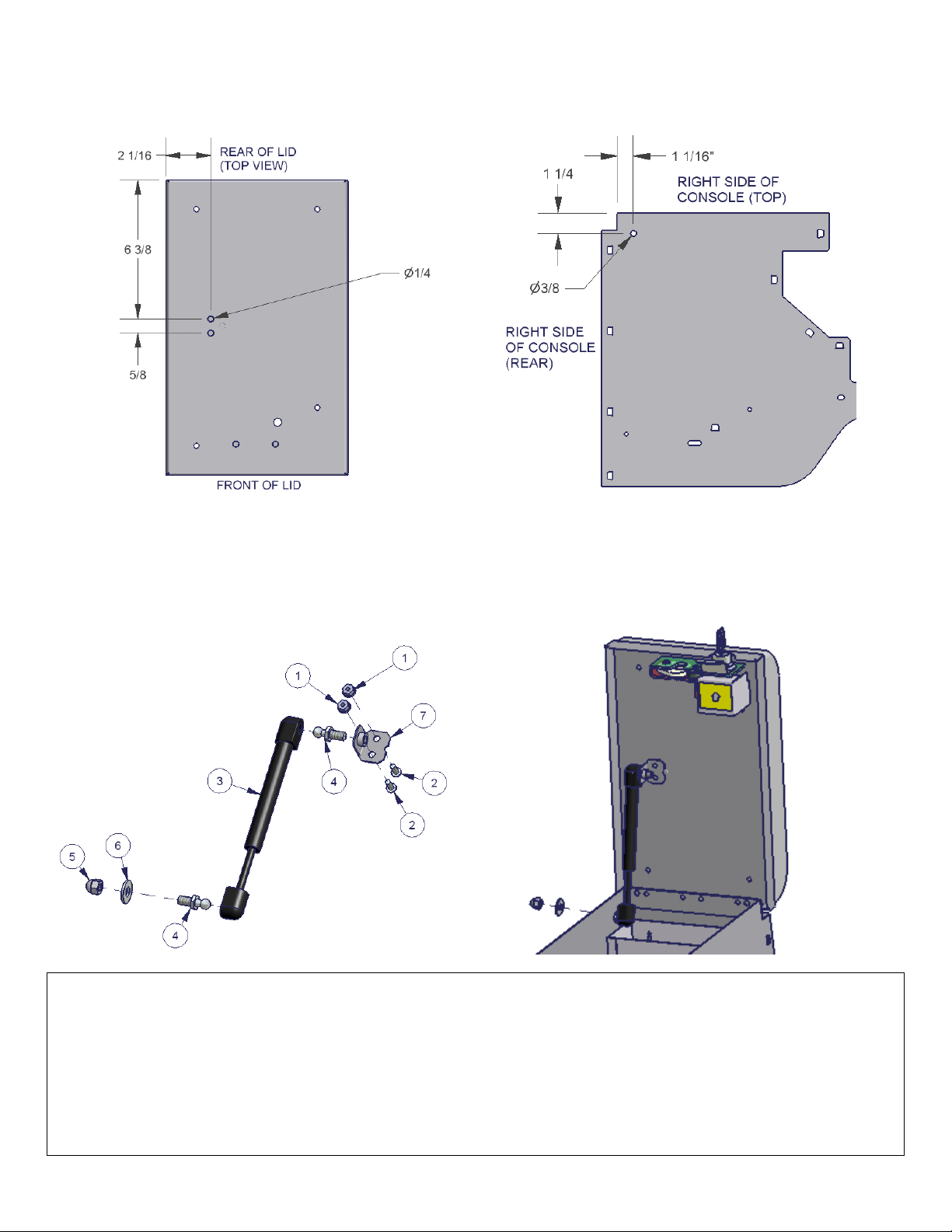
FIGURE 1 FIGURE 2
(STANDARD LID) (STANDARD LID)
FIGURE 3 FIGURE 4
(STANDARD LID) (STANDARD LID)
INSTRUCTIONS TO MOUNT THE GAS STRUT ASSEMBLY IN NON-STANDARD LID HINGE CONFIGURATIONS
PART# 139 JK CONSOLE INSERT, OPENS APPROXIMATELY 82 DEGREES MAX)
1. Remove the padded cushion and mark the spots for (2) ¼” holes to be drilled in the lid to mount the #7 Bracket. Measure from
the rear and right side on the outside top of the lid as illustrated. Drill the (2) ¼” holes in the lid. (See Figure 5)
2. Mark the holes on the right side panel for drilling a 1/4” holes as illustrated and drill it out. (See Figure 5)
3. Fasten the #4 Ball studs to each #7 Brackets as illustrated
4. Attach the top end of the #3 Gas strut to the #7 Bracket for the lid and fasten it to the holes drilled in the lid using the illustrated
hardware. (See Figure 6)
Page 2 of 3 - 06/23/2008 – Rev05192008
Page 3

5. Mount the other #7 Bracket with the #4 Ball stud in the holes drilled in the side with the illustrated hardware (See Figure 5 & 6)
6. Press on the #3 Gas spring in the orientation illustrated with the rod facing down to the #4 Ball stud. (To remove it use a standard
screwdriver to pry up the spring clip on the #3 Gas spring until it pops off, It is not necessary to completely remove the spring)
FIGURE 5 (PART# 139 JK CONSOLE INSERT ONLY)
FIGURE 6 (PART# 139 JK CONSOLE INSERT ONLY)
Page 3 of 3 - 06/23/2008 – Rev05192008
 Loading...