

Page 1
PARTS CHECKLIST
INSTALLATION INSTRUCTIONS
POWER OUTLET #862
Call (970) 564-1762 for Technical Support
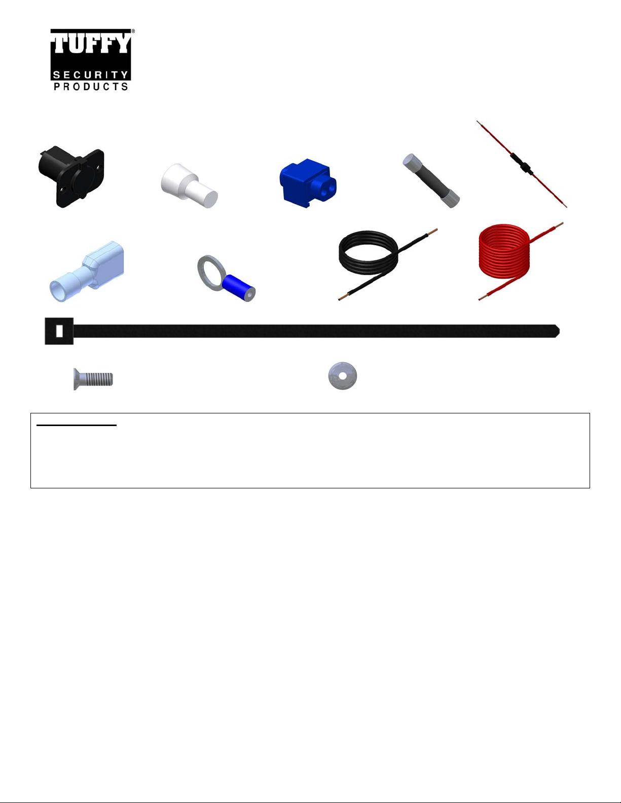
#1 Outlet #10 Crimp cap #9 Tap-in connector #8 Fuse #7 Fuse holder
#4 – (2) Female terminal #12 Ring terminal #6 Black Ground Wire #5 Red Hot wire
#2 – (2) 8-32 X ½” FLAT HEAD #3 – (2) 8-32 HEXWASHER NUT
TOOLS NEEDED
• Phillips head screw driver (Short)
• 11/32” Nut-driver and/or wrench
• Electrical wire cutting, stripping, and crimping tool (For 12 volt outlet installation)
• Electrical volt meter (For 12 volt outlet installation)
#11 – (2) Zip ties
ATTENTION:
This installation should be done by a skilled professional. Tuffy does not warranty any
electrical components or damage caused by them. Improper installation can cause
damage to the vehicle and/or any electronics plugged into the outlet. Make sure there is
no power to the wiring when installing.
Page 1 of 2 - 05/28/2008 – Rev05192008
Page 2

PLEASE READ ALL INSTRUCTIONS THOROUGHLY BEFORE STARTING INSTALLA TION.
1. Locate a suitable location for the outlet on a flat surface with adequate room behind for the electrical components then drill the
required holes for mounting.
2. Locate a 12 Volt 15 Amp rated power source. Make sure it is only live when the ignition is on so unwanted battery run down is
avoided when the vehicle is not running.
3. Attach the Fuse holder (#7 - Fig 1) to the Red (Hot) wire (#5 – Fig 1) using a provided Closed end crimp cap connector (#10 – Fig
1).
4. With the power supply off
connector provided (#9 – Fig 1). Make sure this fuse holder is easily accessible for replacement.
5. Attach the Black (Ground) wire (#6 – Fig 1) to the provided Ring terminal (#12 – Fig 1) then fasten it to an adequately grounded
bolt/surface.
6. Use the provided zip ties (#11 – Fig 1) to support the wires and make sure there is no potential for damage caused by sharp edges.
Cut the wire to the correct length where the outlet will be located and install the crimp on flat female terminals (#4 – Fig 1) on the
end of the Red (Hot) and Black (Ground) wires.
7. Install Fuse (#8 – Fig 1) in Fuse holder (#7 – Fig 1).
8. Using a volt meter test that there is 12 volt power to the Red (Hot) wire and that the Black (Ground) wire is properly grounded.
Turn off power when complete.
9. Fasten the 12 Volt outlet (#1 – Fig 1). Make sure it is oriented so the cover opens hinging up. Make a note of which terminal is
positive and negative. When the wires are hooked up it may be difficult to see the emblems.
10. With the power turned off connect the Red (Hot) wire terminal (#4 – Fig 1) to the corresponding “+” terminal and the Black
(Ground) wire terminal (#4 – Fig 1) to the “-“ terminal on the back of the 12 volt outlet (1 – Fig 1) and test with a volt meter. The
small bottom center connection inside the outlet should have power while the inside connection on the wall perimeter should be
grounded. If this is not clear test an existing outlet in the vehicle and make sure it matches. Do not test power by pluggin g in
electronics.
attach the other end of the Fuse holder (#7 - Fig 1) to a power source using the tap-in squeeze
FIGURE 1
Page 2 of 2 - 05/28/2008 – Rev05192008
 Loading...