

Page 1
INSTALLATION INSTRUCTIONS
2009+ Ram Quad/Crew Cab Under-Seat Storage Security Lid #312
Please read and fill out the enclosed warranty registration card or register online at
tuffyproducts.com/warrantyreg.aspx to activate your warranty.
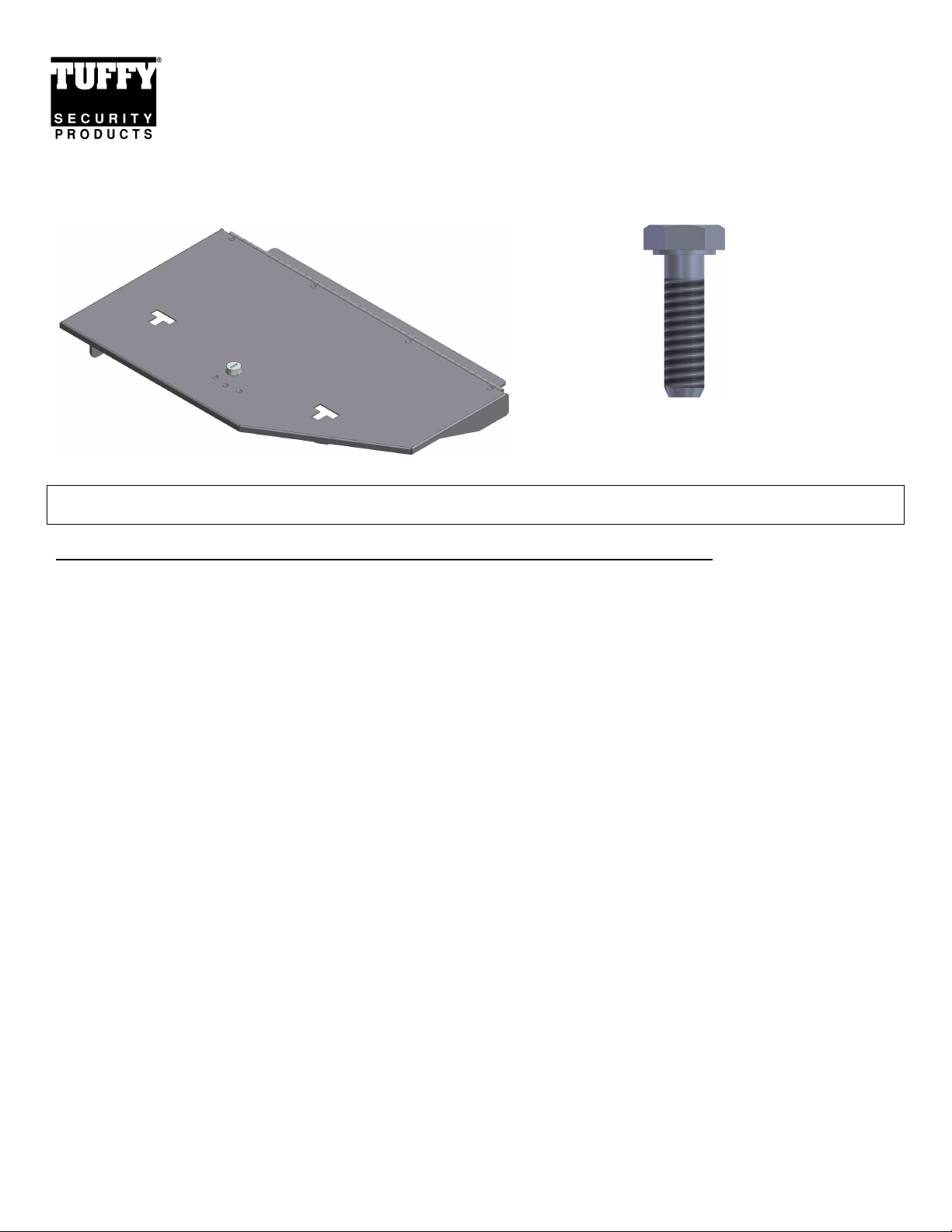
PARTS CHECKLIST SHIPPING PACKAGE CONTENTS
Security Lid #312 #7.1 (2) 5/16”-18 x 1”L Hex-head Bolt
Tools needed for standard installation:
• 18mm Wrench/Socket • 13mm Wrench/Socket
PLEASE READ ALL INSTRUCTIONS THOROUGHLY BEFORE STARTING INSTALLATION.
1. Lift the lower driver’s side portion of the rear seat, and folding platform (if your truck was equipped with them).
2. Using the 18mm wrench/socket remove the large mounting bolts (SEE FIGURE 1, OPPOSITE SIDE) that secure the
forward seat mounts/platform, save for later use.
3. Using the 13mm wrench/socket, remove the nuts that hold the backside of the platform mounting plate.
4. Remove the driver’s side platform, and reinstall the13mm nuts on the studs to prevent loss.
5. Remove the two plastic carpet retaining pins that line up with the mounting holes on the front of the #312(a panel
removal tool, or screwdriver may be necessary), set them aside for reinstallation if you wish to return the vehicle to
stock configuration in the future.
6. Open the #312 Security Lid and place the mount plate over the storage compartment opening.
7. Start, but do not tighten, the large mounting bolts near the hinge to align the unit over the opening. (SEE FIGURE 1)
8. Insert the (2) #7.1 mounting bolts from the shipping package(enclosed with the keys), through the forward holes in the
1/8” thick #312 mount plate and into the factory mounting slots, which held the plastic pins (some downward
pressure on the forward edge of the mount plate may be required, SEE FIGURE 1).
9. Using the 18mm wrench/socket, tighten the large mounting bolts to approx. 20 ft-lbs.
NOTE:
vertical surface of the storage compartment. These bolts are used to prevent the front of the #312 from being pried up in
the front/side, and therefore do not require significant torque.
The mounting slots in Step #8 are not threaded, so the #7.1 bolts may not “clamp” the mounting plate to the
Page 1 of 2 - 10/1/2014 – Rev0
Page 2
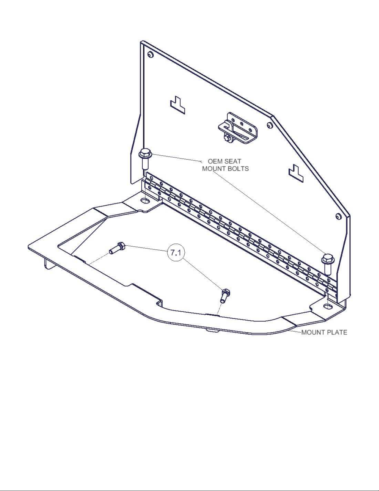
FIGURE 1
Call (970)564-1762 for Technical Support
Page 2 of 2 - 10/1/2014 – Rev0
 Loading...